EMM-3 instruction manual / manual de instrucciones IM425-UE-F v2.2 pag. 5
MENU OF INSTRUMENT PROGRAMMING (SETUP)
For a correct use of the instruments it’s necessary to program the transformation rate of the CT’s and the transformation
rate of the eventually voltage transformers. The values set are hold also in absence of the auxiliary power supply.
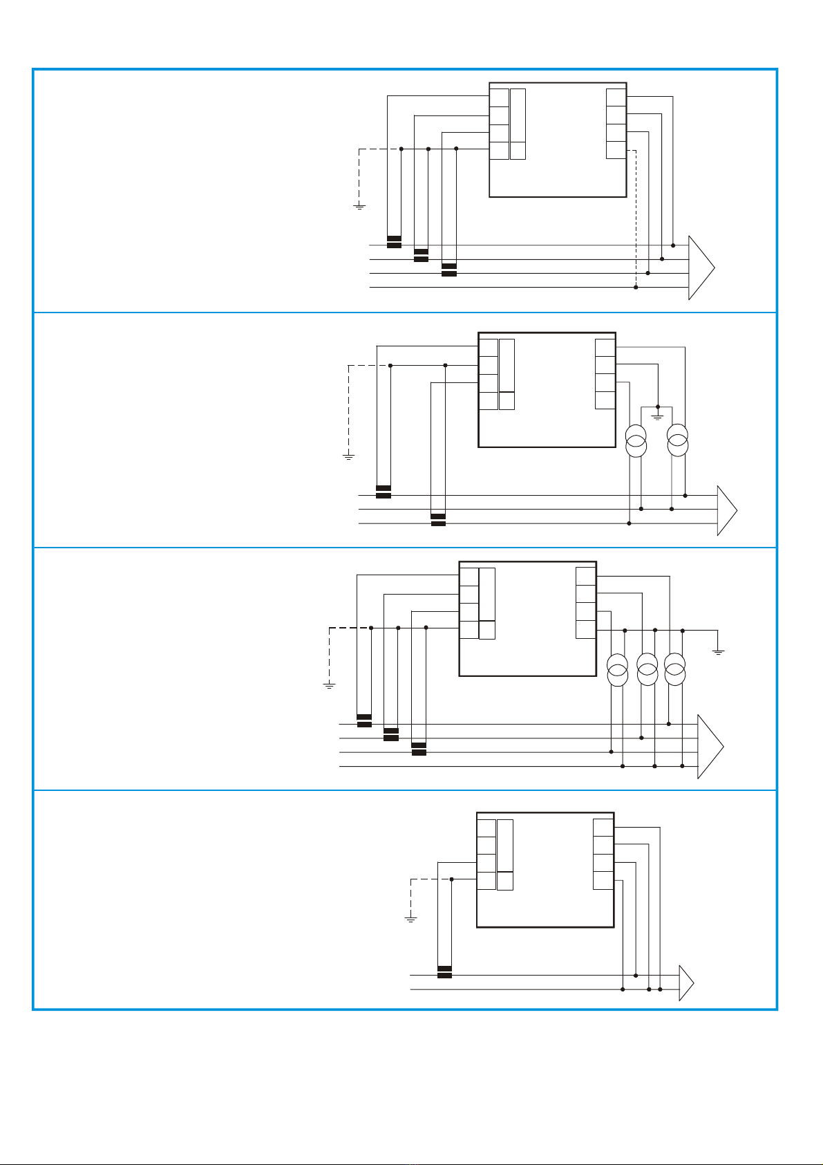
- Programming of the transformation rate of the external CT’s
The programming of the CT’s rate considered as the rate between primary and secondary (example: with CT 1000/5, we
must set 200), must be done with the push-button on the front panel.
After the connecting the power supply to the instrument and waiting few
seconds (all LED’s will glow and the first indication of the firmware appears
on the display and all segments will glow later), press and keep pressing the
key Aduring 5 seconds, when the message
will appear on the
display E. By pressing the key Aagain it will appear the message
(current transformer) and the value of the transformation rate (set to 1 by the
manufacturer).
To increase the value press the Bbutton or Abutton reduce the value (the
variation is unit for unit).
To increase the speed up the value setting, it’s necessary to hold pressed the
Bor Abutton, the variation will happen successively by tens and hundreds.
To come back to increase or to reduce the value on unit by unit way, it’s
necessary to release and to press the key again.
To confirm the value set press the Abutton; in this way the instrument will
pass to the successive programming.
If no key is pressed during a 10-second interval of time, the instrument will exit automatically from programming, without
saving the selected value.
- Programming of the transformation rate of the external voltage transformers
After the precedent programming, the message
(voltage transformer) will appear on display Etogether with the value
of the transformation rate of the external VT (set to 1 by the manufacturer), considered as the rate between primary and
secondary (example with VT 15/o.1 kV the value will be 150).
In the same way as programming the CT’s rate, it will be possible to set this value. If external VT are not used the value
to set will be 1.
To confirm the value press the Abutton. The instrument will exit from programming and it will enter in the visualisation
modality.
-Activating or cancelling the automatic scrolling
This allows selecting ON for activating or OFF for cancelling the automatic scrolling of the measures visualisation.
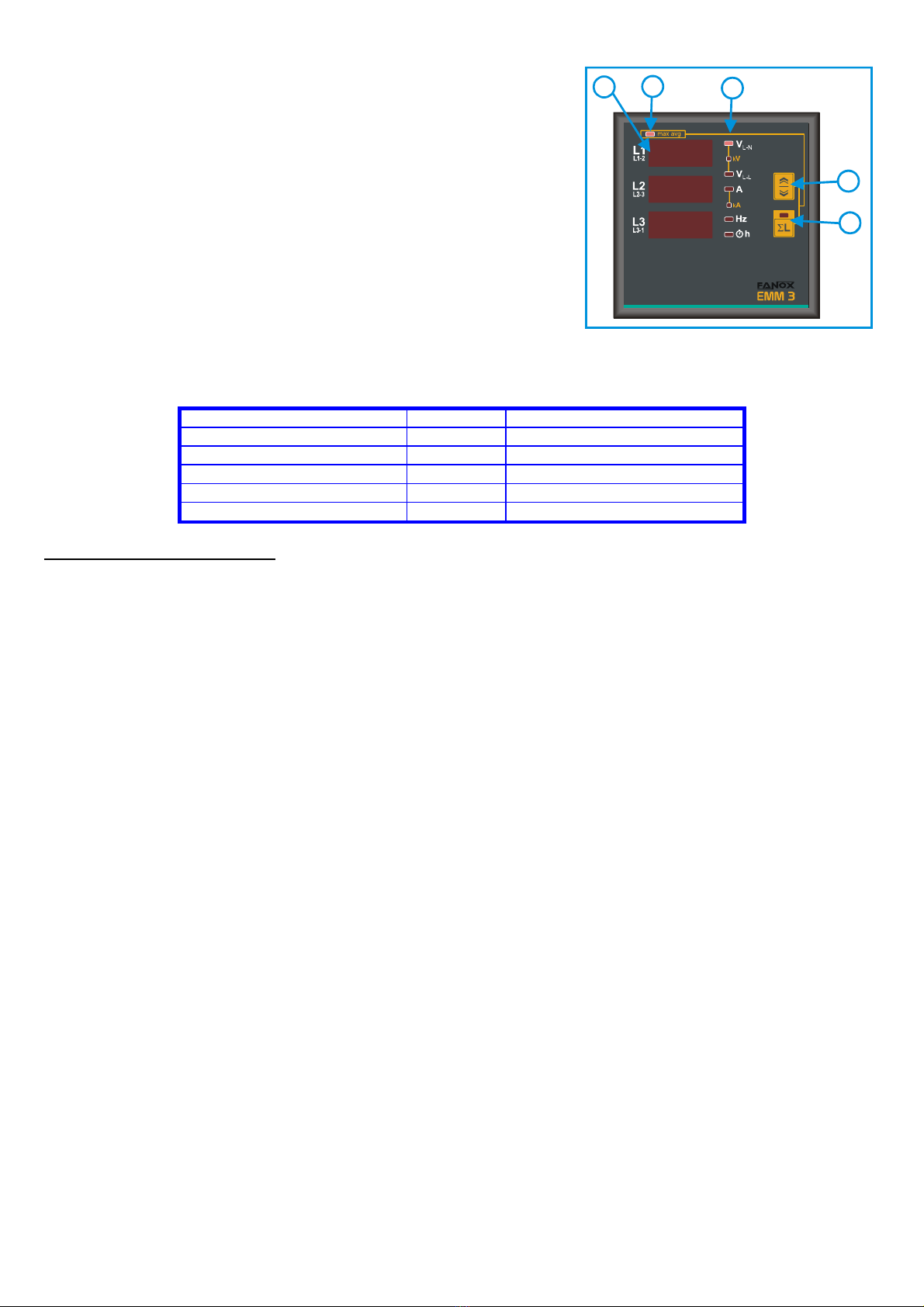
MEASURES VISUALISATION
The measures reading is visualised on the display E, showing the three phase measures (L1, L2 y L3 respectively) of the
indicated parameter by the CLED. For measuring the phase to phase voltage (V L-L), the three measures are understood
VL1-L2, V L2-L3, V L3-L1 respectively, as indicated on the front plate.
The selection of the parameter to be visualised is made by pressing the key B. It will be indicated by the CLED.
By pressing the key A, the selected parameters will be visualised on display E, as three phase values (average of the
individual phases for voltages and currents) with the corresponding lighting of the LED, placed internally in the key. In
This case, by pressing the key Bit will be possible to show: either the three-phase voltage, calculated as the average of
the phase voltage, or the phase to phase voltages (it will be indicated by the corresponding LED C). In the mode of
visualisation of the three-phase system (LED 6L glowing), we will have following lights and readings:
- LED VL-N or (VL-L) and the display L1 will show the average phase voltage (or average phase to phase)
- LED Aand the display L2 will show the average current
- LED Hz and the display L3 will show the frequency on line L1
By pressing the Akey again, it will return to visualise the phase values.
Please note that the unit value may be expressed in kilo, when the corresponding LED Care glowing (indicated in the
front plate as k).
The visualised frequency is referred to the line L1.
HOUR METER VISUALISATION
Pressing the Bkey, after the frequency visualisation, the phase hours counter will appear on the displays. The led his
on. The reading of the meters uses the 6 digits (maximum reading 99999.9) of the display E: the measure comes
visualised in such a way that, the display L1 will show the first 3 digits, the display L2 the second 3 digits and the display
L3 the identification of the corresponding hour meter (hL1, hL2 or hL3).
The hours counter is activated when the current of the corresponding phase exceeds the 1% of the end-scale.
B
C
C
E
D
CT0
001