manuals.online logo
Brands
  1. Home
  2. •
  3. Brands
  4. •
  5. Faria
  6. •
  7. Antenna
  8. •
  9. Faria GPS 100 User manual

Faria GPS 100 User manual

Popular Antenna manuals by other brands

DAVIS Windex AV 3160 installation instructions

DAVIS

DAVIS Windex AV 3160 installation instructions

Belden Hirschmann BAT-ANT-N-14G-IP23 Mounting instruction

Belden

Belden Hirschmann BAT-ANT-N-14G-IP23 Mounting instruction

Vtronix YHK Fitting instructions

Vtronix

Vtronix YHK Fitting instructions

KVH Industries TracVision 6 Technical manual

KVH Industries

KVH Industries TracVision 6 Technical manual

Leica Geosystems GS10 user manual

Leica Geosystems

Leica Geosystems GS10 user manual

Sirio Antenne Gain-Master manual

Sirio Antenne

Sirio Antenne Gain-Master manual

Sony VCA-41 Installation/connections

Sony

Sony VCA-41 Installation/connections

ZCG Y100 Series installation guide

ZCG

ZCG Y100 Series installation guide

Advantech Wireless INTREPID120 Assembly instructions

Advantech Wireless

Advantech Wireless INTREPID120 Assembly instructions

Cerio ANT-10AO installation guide

Cerio

Cerio ANT-10AO installation guide

Alfa Network APA-L01 Specifications

Alfa Network

Alfa Network APA-L01 Specifications

Naval PR-422CA Operation manual

Naval

Naval PR-422CA Operation manual

Feig Electronic ID ISC.ANTH200/200 Series manual

Feig Electronic

Feig Electronic ID ISC.ANTH200/200 Series manual

TERK Technologies TV44 owner's manual

TERK Technologies

TERK Technologies TV44 owner's manual

TERK Technologies SIR3 owner's manual

TERK Technologies

TERK Technologies SIR3 owner's manual

Directive Systems & Engineering DSE2324LYRMK quick start guide

Directive Systems & Engineering

Directive Systems & Engineering DSE2324LYRMK quick start guide

HP J8999A instructions

HP

HP J8999A instructions

MobilSat MSP-S Mounting instructions

MobilSat

MobilSat MSP-S Mounting instructions

manuals.online logo
manuals.online logoBrands
  • About & Mission
  • Contact us
  • Privacy Policy
  • Terms and Conditions

Copyright 2025 Manuals.Online. All Rights Reserved.

GPS100 Antenna
IS0216
rev. A ecr#5186 02/2005
Owners’s Manual
All manuals and user guides at all-guides.com
all-guides.com
FCC Statement
Note: This equipment has been tested and found to comply with the limits for a Class B digital device, pursuant to Part 15 of the FCC
Rules. These limits are designed to provide reasonable protection against harmful interference in a normal installation. This equipment
generates, uses and can radiate radio frequency energy and, if not installed and used in accordance with the instructions, may cause
harmful interference to radio communications. However, there is no guarantee that interference will not occur in a particular installation.
If this equipment does cause harmful interference to radio or television reception, which can be determined by turning the equipment
off and on, the user is encouraged to try to correct the interference by one or more of the following measures:
Reorient or relocate the receiving antenna
Increase the separation between the equipment and receiver
Connect the equipment into an output on a circuit different from that to which the receiver is connected
Consult the dealer or an experienced technician for help
A shielded cable must be used when connecting a peripheral to the serial ports
Important
It is the owner’s sole responsibility to install and use the antenna in a manner that will not cause accidents, personal
injury or property damage. The user of this product is solely responsible for observing safe boating practices.
Global Positioning System: The Global Positioning System (GPS) is operated by the US government which is solely
responsible for its operation, accuracy and maintenance. The GPS system is subject to changes which could affect the
accuracy and performance of all GPS equipment anywhere in the world.
Installation: If installation is not correct, the unit can not perform at its designed potential. If in doubt, consult your Faria
dealer. Ensure that any holes made are in a safe position and will not weaken the boat’s structure. If in doubt, consult
a qualified boat builder.
FARIA MARINE INSTRUMENTS, USA DISCLAIMS ALL LIABILITY FOR ANY USE OF THIS PRODUCT IN A WAY THAT
MAY CAUSE ACCIDENTS, DAMAGE OR THAT MAY VIOLATE THE LAW.
Governing language: This statement, any instruction manuals, user guides and other information relating to the product
(Documentation) may be translated to, or has been translated from, another language (Translation). In the event of any
conflict between any Translation of the Documentation, the English language version of the Documentation will be the
official version of the Documentation.
GPS 100: includes 10 m (32.8 ft)
cable or
This installation guide
For surface mounting:
Gasket (doubles as mounting
template)
4 threaded rods: thread M4 x 40 mm
(2")
4 washers
4 nuts
For pole mounting:
Pole mount adaptor
4 screws
Also available:
GPS 100: 10 m (32.8 ft) extension
cable
1 Introduction
What comes with your GPS 100 antenna
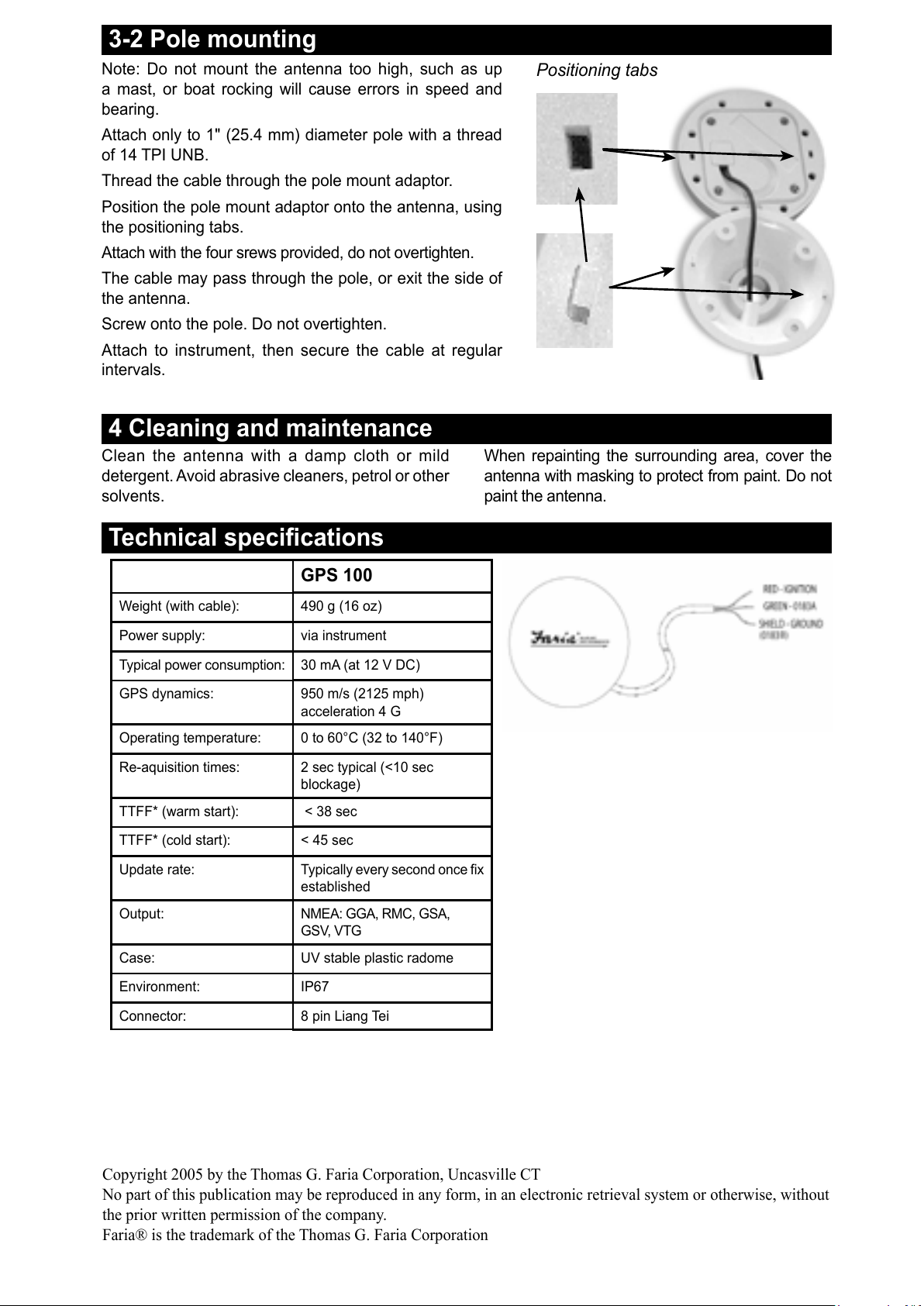
This installation manual describes how to install Faria’s GPS100 antenna using two methods:
surface mounting and pole mounting.
GPS 100
All manuals and user guides at all-guides.com
Ensure that the
channel is filled
with silicon to
provide a seal when
gasket is in place.
5. Attach the four threaded pins to the antenna.
6. Peel the plastic off the gasket.
7. Place antenna in final position.
8. Attach the four nuts to
the threaded rod. Do not
overtighten.
9. Attach to instrument, then
secure the cable at regular
intervals.
2 Choosing a suitable location for the antenna
Mount the antenna with a good view of the sky and
horizon. The view should not be blocked by large
parts of the superstructure.
The unit can be under glass, perspex, fibreglass
or fabric, but not under metal or wood.
Mount the antenna away from any source of
electrical signals or noise. Do not mount the
antenna within 3 m (10 ft) of a radio transmitter
antenna or within 0.5 m (20") of the plane of a
radar antenna.
Do not fit the antenna too high, such as up a
mast, or boat rocking will cause errors in speed
and bearing.
Do not mount the antenna where it can be
used as a hand hold, where it will interfere with
the operation of the boat or where it might be
submerged.
Mount the antenna within the connection range
of the cable in it's final secured position, keeping
the cable away from sources of electrical signals
or noise and ensuring the cable is not pinched
or crushed.
3-1 Surface mounting
Select a suitable location which allows access for affixing nuts and has a suitable mounting surface. Avoid
high traffic areas where the antenna may be a tripping hazard.
Ensure that any holes made are in a safe position and will not weaken the boat’s structure. If in doubt,
consult a qualified boat builder.
3 Mounting
There are two mounting options:
Pole mountedSurface mounted
1. Clean the surface where the antenna will be
mounted.
2. Peel the back off one
side of the gasket and
stick the gasket in the
final mounting position.
3. Using the gasket as
a template, drill four
4 mm (5/32") holes.
4. The cable may
either pass through the surface the antenna
is mounted on, or exit the side of the
antenna:
4A For GPS 100 if
passing cable through
the surface, drill an 18 mm
(23/32") hole for the
connector.
4B If exiting the side of the
antenna, remove three
plastic tabs, then seal
cable into place with
silicon.
Cable
Fill with
silicon
Gasket
All manuals and user guides at all-guides.com
Copyright 2005 by the Thomas G. Faria Corporation, Uncasville CT
No part of this publication may be reproduced in any form, in an electronic retrieval system or otherwise, without
the prior written permission of the company.
Faria® is the trademark of the Thomas G. Faria Corporation
Clean the antenna with a damp cloth or mild
detergent. Avoid abrasive cleaners, petrol or other
solvents.
When repainting the surrounding area, cover the
antenna with masking to protect from paint. Do not
paint the antenna.
3-2 Pole mounting
Note: Do not mount the antenna too high, such as up
a mast, or boat rocking will cause errors in speed and
bearing.
Attach only to 1" (25.4 mm) diameter pole with a thread
of 14 TPI UNB.
Thread the cable through the pole mount adaptor.
Position the pole mount adaptor onto the antenna, using
the positioning tabs.
Attach with the four srews provided, do not overtighten.
The cable may pass through the pole, or exit the side of
the antenna.
Screw onto the pole. Do not overtighten.
Attach to instrument, then secure the cable at regular
intervals.
Technical specifications
GPS 100
Weight (with cable): 490 g (16 oz)
Power supply: via instrument
Typical power consumption: 30 mA (at 12 V DC)
GPS dynamics: 950 m/s (2125 mph)
acceleration 4 G
Operating temperature: 0 to 60°C (32 to 140°F)
Re-aquisition times: 2 sec typical (<10 sec
blockage)
TTFF* (warm start): < 38 sec
TTFF* (cold start): < 45 sec
Update rate: Typically every second once fix
established
Output: NMEA: GGA, RMC, GSA,
GSV, VTG
Case: UV stable plastic radome
Environment: IP67
Connector: 8 pin Liang Tei
4 Cleaning and maintenance
Positioning tabs
All manuals and user guides at all-guides.com