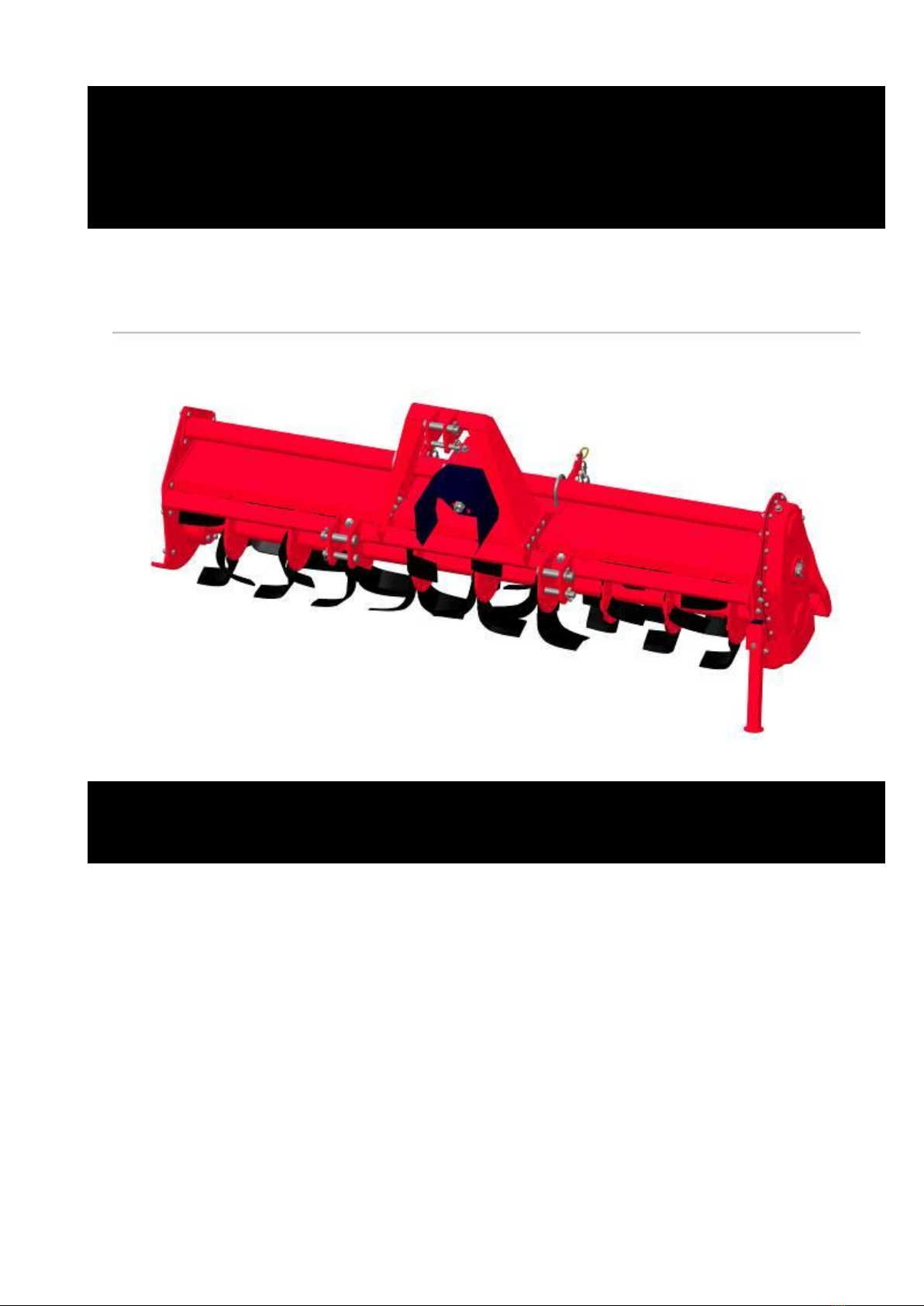
FTH-Series Rotary Tillers
5
3. SAFETY
Proper use of equipment, a strict observance of the safety messages listed below and application of
all reasonable practices to avoid any risks, prevents accidents or injury, allows the machine to work
better and longer, and minimize failures.
The manufacturer assumes no liability for any damage resulting from not applying the behavioral
rules indicated into the manual.
3.1. GENERAL SAFETY INSTRUCTION
The machine must be used only by authorized and well trained operators. The operator must have
read and understood the instructions of this manual, it must make adequate preparation for the
proper use of the machine and must hold a driving license. In case of doubt about the use of the
machine and/or the interpretation of this manual, the operator must contact the Manufacturer or
the Dealer.
The manual must always remain with the machine. In case of loss or damage, request a new copy
to the Manufacturer or your Dealer.
Follow strictly the rules prescribed by the safety pictograms applied to the machine.
Be sure that all safety pictograms are legible. If pictograms are worn, they must be replaced with
others obtained from the Manufacturer, and placed in the position indicated by this manual.
Before using the machine, make sure that all safety devices are installed and in good working
conditions. In case of damages of shields, replace them immediately.
Is absolutely forbidden to remove or alter safety devices.
Before starting, and during operation of the tiller, make sure there are no people or animals in the
operation area: the machine can project material from the back, with risks of serious injury or death.
Pay maximum attention to avoid any accidental contact with rotating parts of the machine.
During operation, adjustment, maintenance, repairing or transportation of the machine, the operator
must always use appropriate Personal Protective Equipment (PPE).
Do not operate the implement while wearing loose fitting clothing that can give rise to entanglement
in parts of the machine.