Farmet FANTOM FX 470 NS User manual
FANTOM
FFXX 447700 NNSS
Edition: 3Effective from: 1.1.2018
FARMET a.s.
Jiřinková 276
552 03 Česká Skalice, CZ
phone: +420 491 450 111
fax: +420 491 450 136
GSM: +420 774 715 738
IČ: 46504931
DIĆ: CZ46504931
www.farmet.cz
e-mail: [email protected]
OPERATING MANUAL
FFAANNTTOOMM
FFXX 447700 NNSS

2 | 37
Prepared by: Technical Department, Farmet a.s.
on 24.4.2019, changes reserved

PREFACE
3 | 37
PREFACE
Dear customer,
The agricultural machine you have purchased is a high-quality product of Farmet a.s. Česká Skalice.
You can fully utilise the advantages of your machine after thoroughly studying the operating manual.
The serial number of the machine is punched on the production label and written in the operating
manual (Your Machine Characteristics). This machine serial number must be stated whenever ordering spare
parts for possible repairs. The production label is located on the frame .
Use only spare parts for these machines according to the Spare parts catalogue officially issued by
the manufacturer, Farmet a.s. Česka Skalice.
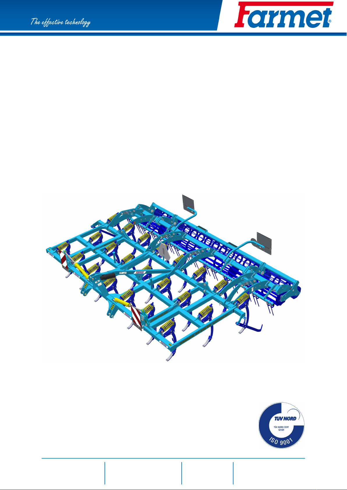
Possibilities of Use of the Cultivator
The FANTOM cultivator is designed for cultivation of all types of soils up to a processing depth of 15 cm.
Your Machine Characteristics :
MACHINE TYPE :
MACHINE SERIAL NUMBER :
SPECIAL DESIGN OR ACCESSORIES :


PREFACE
5 | 37
Contents
PREFACE . . . . . . . . . . . . . . . . . . . . . . . . . . . . . . . . . . . . . . . . . . . . . . . . . . . . . . . . . . . . . . . . . . . . . . . . . . . . . . . . . . . . . . . . . . . . . . . . . . . . . . . . . . . . . . . . . . . . . . . . . . . . . . . . . 3
1 MACHINE LIMIT PARAMETERS . . . . . . . . . . . . . . . . . . . . . . . . . . . . . . . . . . . . . . . . . . . . . . . . . . . . . . . . . . . . . . . . . . . . . . . . . . . . . . . . . . . . . . . 7
1.1 Technical parameters. . . . . . . . . . . . . . . . . . . . . . . . . . . . . . . . . . . . . . . . . . . . . . . . . . . . . . . . . . . . . . . . . . . . . . . . . . . . . . . . . . . . . . . . . . 7
1.2 Safety statement. . . . . . . . . . . . . . . . . . . . . . . . . . . . . . . . . . . . . . . . . . . . . . . . . . . . . . . . . . . . . . . . . . . . . . . . . . . . . . . . . . . . . . . . . . . . . . . . . . 7
2 GENERAL INSTRUCTIONS FOR USE . . . . . . . . . . . . . . . . . . . . . . . . . . . . . . . . . . . . . . . . . . . . . . . . . . . . . . . . . . . . . . . . . . . . . . . . . . . . 8
3 MACHINE TRANSPORT USING TRANSPORT MEANS . . . . . . . . . . . . . . . . . . . . . . . . . . . . . . . . . . . . . . . . . . . . 10
4 MACHINE HANDLING USING LIFTING EQUIPMENT . . . . . . . . . . . . . . . . . . . . . . . . . . . . . . . . . . . . . . . . . . . . . . . . 11
5 WORK SAFETY LABELS. . . . . . . . . . . . . . . . . . . . . . . . . . . . . . . . . . . . . . . . . . . . . . . . . . . . . . . . . . . . . . . . . . . . . . . . . . . . . . . . . . . . . . . . . . . . . . . . . . 12
6 DESCRIPTION. . . . . . . . . . . . . . . . . . . . . . . . . . . . . . . . . . . . . . . . . . . . . . . . . . . . . . . . . . . . . . . . . . . . . . . . . . . . . . . . . . . . . . . . . . . . . . . . . . . . . . . . . . . . . . . . . . . . 15
6.1 Working parts of the machine. . . . . . . . . . . . . . . . . . . . . . . . . . . . . . . . . . . . . . . . . . . . . . . . . . . . . . . . . . . . . . . . . . . . . . . . . . 15
7 MACHINE ASSEMBLY AT THE CUSTOMER. . . . . . . . . . . . . . . . . . . . . . . . . . . . . . . . . . . . . . . . . . . . . . . . . . . . . . . . . . . . . . . . 16
8 COMMISSIONING. . . . . . . . . . . . . . . . . . . . . . . . . . . . . . . . . . . . . . . . . . . . . . . . . . . . . . . . . . . . . . . . . . . . . . . . . . . . . . . . . . . . . . . . . . . . . . . . . . . . . . . . . . . . . . 17
8.1 Agregation to a tractor . . . . . . . . . . . . . . . . . . . . . . . . . . . . . . . . . . . . . . . . . . . . . . . . . . . . . . . . . . . . . . . . . . . . . . . . . . . . . . . . . . . . . . 18
8.2 Hydraulics. . . . . . . . . . . . . . . . . . . . . . . . . . . . . . . . . . . . . . . . . . . . . . . . . . . . . . . . . . . . . . . . . . . . . . . . . . . . . . . . . . . . . . . . . . . . . . . . . . . . . . . . . . . 18
8.3 Folding and unfolding of the machine. . . . . . . . . . . . . . . . . . . . . . . . . . . . . . . . . . . . . . . . . . . . . . . . . . . . . . . . . . . . . 19
8.4 Description of the share/chisel replacement . . . . . . . . . . . . . . . . . . . . . . . . . . . . . . . . . . . . . . . . . . . . . . . . 20
9 REAR ACCESSORIES. . . . . . . . . . . . . . . . . . . . . . . . . . . . . . . . . . . . . . . . . . . . . . . . . . . . . . . . . . . . . . . . . . . . . . . . . . . . . . . . . . . . . . . . . . . . . . . . . . . . . . 21
9.1 Setting levelling . . . . . . . . . . . . . . . . . . . . . . . . . . . . . . . . . . . . . . . . . . . . . . . . . . . . . . . . . . . . . . . . . . . . . . . . . . . . . . . . . . . . . . . . . . . . . . . . . 23
9.1.1 Setting the angle of rear levelling . . . . . . . . . . . . . . . . . . . . . . . . . . . . . . . . . . . . . . . . . . . . . . . . . . . . . . . . . . 23
10 MACHINE TRANSPORT ON ROADS . . . . . . . . . . . . . . . . . . . . . . . . . . . . . . . . . . . . . . . . . . . . . . . . . . . . . . . . . . . . . . . . . . . . . . . . . . 24
11 MACHINE ADJUSTMENT. . . . . . . . . . . . . . . . . . . . . . . . . . . . . . . . . . . . . . . . . . . . . . . . . . . . . . . . . . . . . . . . . . . . . . . . . . . . . . . . . . . . . . . . . . . . . . . 25
11.1 Adjusting the working depth of the machine . . . . . . . . . . . . . . . . . . . . . . . . . . . . . . . . . . . . . . . . . . . . . . . 26
11.2 Setting side deflectors. . . . . . . . . . . . . . . . . . . . . . . . . . . . . . . . . . . . . . . . . . . . . . . . . . . . . . . . . . . . . . . . . . . . . . . . . . . . . . . . . . . . 29
11.3 Share securing. . . . . . . . . . . . . . . . . . . . . . . . . . . . . . . . . . . . . . . . . . . . . . . . . . . . . . . . . . . . . . . . . . . . . . . . . . . . . . . . . . . . . . . . . . . . . . . . . 30
12 MACHINE MAINTENANCE AND REPAIRS . . . . . . . . . . . . . . . . . . . . . . . . . . . . . . . . . . . . . . . . . . . . . . . . . . . . . . . . . . . . . . . . 31
13 MACHINE STORAGE. . . . . . . . . . . . . . . . . . . . . . . . . . . . . . . . . . . . . . . . . . . . . . . . . . . . . . . . . . . . . . . . . . . . . . . . . . . . . . . . . . . . . . . . . . . . . . . . . . . . . . 32
14 MACHINE LUBRICATION SCHEDULE. . . . . . . . . . . . . . . . . . . . . . . . . . . . . . . . . . . . . . . . . . . . . . . . . . . . . . . . . . . . . . . . . . . . . . . . 33
15 ENVIROMENTAL PROTECTION . . . . . . . . . . . . . . . . . . . . . . . . . . . . . . . . . . . . . . . . . . . . . . . . . . . . . . . . . . . . . . . . . . . . . . . . . . . . . . . . . . 34
16 MACHINE DISPOSAL AFTER SERVICE LIFE EXPIRY. . . . . . . . . . . . . . . . . . . . . . . . . . . . . . . . . . . . . . . . . . . . 35
17 SERVICING AND WARRANTY CONDITIONS . . . . . . . . . . . . . . . . . . . . . . . . . . . . . . . . . . . . . . . . . . . . . . . . . . . . . . . . . . . 36
17.1 Servicing. . . . . . . . . . . . . . . . . . . . . . . . . . . . . . . . . . . . . . . . . . . . . . . . . . . . . . . . . . . . . . . . . . . . . . . . . . . . . . . . . . . . . . . . . . . . . . . . . . . . . . . . . . . 36
17.2 Warranty . . . . . . . . . . . . . . . . . . . . . . . . . . . . . . . . . . . . . . . . . . . . . . . . . . . . . . . . . . . . . . . . . . . . . . . . . . . . . . . . . . . . . . . . . . . . . . . . . . . . . . . . . . . 36


7 | 37
MACHINE LIMIT PARAMETERS
1 MACHINE LIMIT PARAMETERS
• The machine is designed for soil ploughing up to a depth of 15 cm when agricultural soil cultivation.
Another type of use exceeding the determined purpose is forbidden.
• The machine is only operated by one person – the tractor operator.
• Machine operator must not use the machine in a different way, especially:
Transport of persons and animals on the machine structure,
Transport of burdens on the machine structure,
Aggregation of the machine with another towing equipment than stated in Chapter „8.1“.
1.1 Technical parameters
PARAMETERS FANTOM FX 470 NS
Working width 4,68 m
Transport width 3 m
Transport height 1,9 m
Machine total length 3,5 m
Working depth max. 15 cm
Number of shares 22
Working performance 3,7 –5,6 ha/h
Towing means 160 – 220 kW*
Working speed 8 - 12 km/h
Maximum transport speed 20 km/h
Maximum slope grade (°) 6
Machine weight 2030 kg
* Recommended towing means, the real towing force may significantly vary according to the processing
depth, soil conditions, land slope, working body wear and adjustment.
1.2 Safety statement
This warning sign warns about an immediate dangerous situation ending with death or
severe injury.
This warning sign warns about a dangerous situation ending with death or severe injury.
This warning sign warns about a situation that may end with a smaller or slight injury. It
also warns about dangerous actions related to the activity that could lead to an injury.

8 | 37
GENERAL INSTRUCTIONS FOR USE
2 GENERAL INSTRUCTIONS FOR USE
• The machine is made in accordance with the latest equipment state and approved safety
regulations. However, dangers of user or third person injury or machine damage or
creation of other material damage may arise during use.
• Use the machine only in a technically sound condition, in accordance with its purpose,
aware of possible dangers, and while adhering to the safety instructions of this operating
manual! The manufacturer is not liable for damages caused by the use of the machine
that is in contradiction with the limit parameters of the machine and with the
instructions for the use of the machine . The user bears the risk.
Immediately remove especially the failures that may negatively affect safety!
• Machine operation may be performed by a person authorised by the operator under
these conditions :
• It must own a valid driver's licence of the corresponding category,
• It must be demonstrably familiarised with the safety regulations for work with the
machine and must practically master the machine operation,
• The machine may not be operated by juveniles,
• It must know the meaning of the safety signs located on the machine. Their
respecting is important for safe and reliable machine operation.
• Maintenance and servicing repairs on the machine may only be performed by a person :
• Authorised by the operator,
• Educated in the machinery field with knowledge of repairs of similar machines,
• Demonstrably familiarised with safety regulations for work with the machine,
• During a repair of a machine connected to a tractor, it must own a driver's licence of
the corresponding category.
• Machine operator must secure the safety of other persons when working with the
machine or transporting the machine.
• During machine work in the field or during transport, the operator must control the
machine from the tractor's cabin.
• The operator may enter the machine structure only with the machine at rest and blocked
against movement, namely only for these reasons :
• Adjustment of the machine working parts,
• Repair and maintenance of the machine,
• When stepping on the machine, do not step on roller, tyres or other rotary parts. Those
may turn and you can cause very serious injuries by the subsequent fall.
• Any changes or modifications of machine may be performed only with written consent of
the manufacturer.
For possible damage arisen due to ignoring this instruction, the producer bears no
responsibility.
The machine must be maintained equipped with prescribed accessories and equipment
including safety marking.
All warning and safety signs must be legible and in their places. In case of damage or loss,
these signs must be immediately renewed.
• The operator must have the Operating Manual with the work safety requirements
available at any time when working with the machine.

GENERAL INSTRUCTIONS FOR USE
• The operator must not consume alcohol, medicines, narcotic and hallucinogenic
substances that decrease his attention and coordination capabilities while using the
machine.
If the operator must use medicines prescribed by a physician or uses freely sold
medicines, he must be informed by a physician, whether he is capable of responsible and
safe operation of the machine under these circumstances.
Protective equipment
For operation and maintenance use:
• tight clothes
• protective gloves and goggles against dust and
sharp parts of the machine.
9 | 37

10 | 37
MACHINE TRANSPORT USING TRANSPORT MEANS
3 MACHINE TRANSPORT USING TRANSPORT MEANS
• The transport means designed for machine transport must have the load capacity minimally
identical with the weight of the transported machine. The total weight of the machine is stated
on the production label.
• The dimensions of the transported machine including the transport means must comply with
the valid regulations for road traffic (decrees, laws).
• The transported machine must be always fastened to the transport means so that its
spontaneous loosening could not happen.
• The carrier is responsible for damage caused by the loosening of incorrectly or insufficiently
fastened machine to the transport means.

11 | 37
MACHINE HANDLING USING LIFTING EQUIPMENT
4 MACHINE HANDLING USING LIFTING EQUIPMENT
• The lifting equipment and tying means designed for handling of the machine must have their
load capacity at least identical with the weight of the handled machine.
• Machine fastening for handling may only be performed in places designed for that and
marked with self-adhesive labels showing the "chain" symbol.
• After fastening (suspending) at designated points, it is forbidden to move in the space of
possible reach of the handled machine.
12 | 37
WORK SAFETY LABELS
5 WORK SAFETY LABELS
Warning safety labels serve for operator protection.
General:
• Strictly observe the warning safety labels.
• All safety instructions also apply to other users.
• Upon damage or destruction of the aforementioned "SAFETY LABEL" located on the machine, THE
OPERATOR IS OBLIGED TO REPLACE IT WITH A NEW ONE!!!
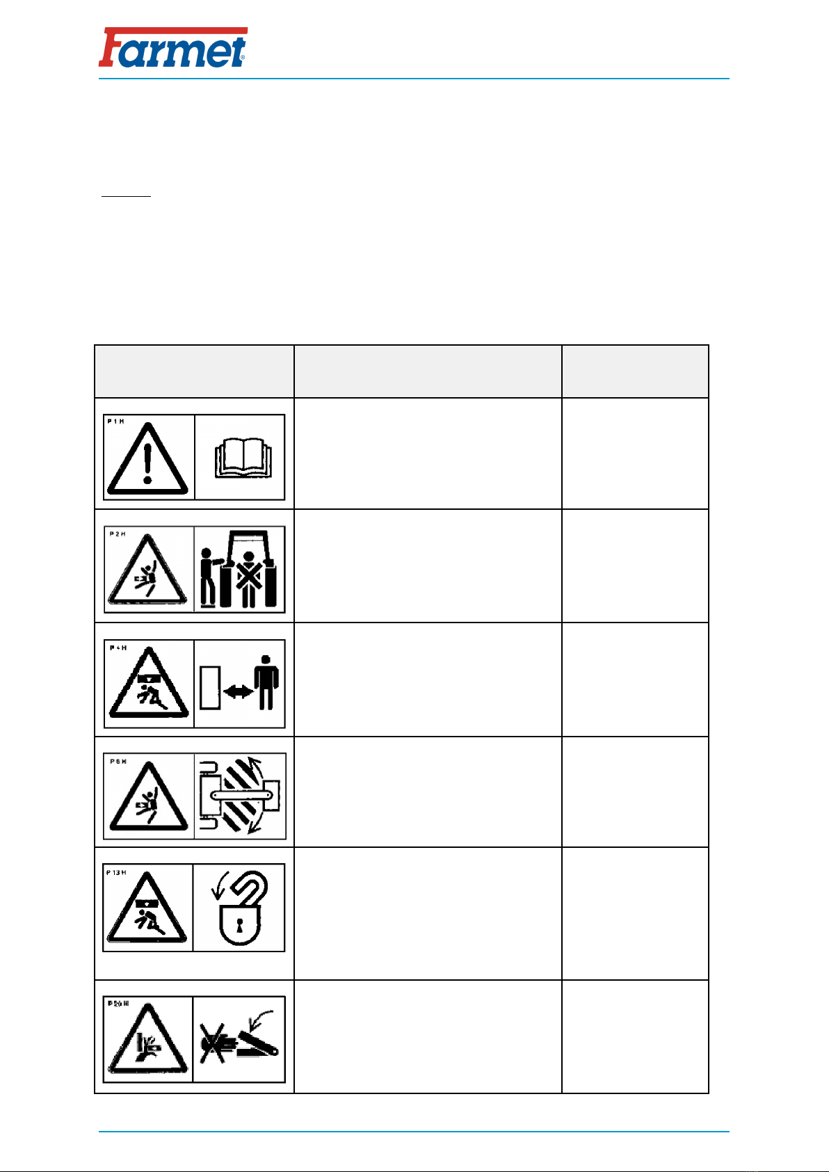
• The position, appearance and the precise meaning of the work safety labels on the machine are
defined in the following tables and the figure .
WARNING SAFETY LABEL LABEL TEXT MACHINE
POSITION
Before handling the machine, carefully read
the operating manual.
Observe the instructions and safety
regulations for machine operation during
use.
P 1 H
When connecting or disconnecting, do not
step between the tractor and the machine,
also do not enter this space, if the tractor
and the machine are not at rest and the
engine is not turned off.
P 2 H
Stay out of reach of the drawn-up machine. P 4 H
Stay outside the reach of the tractor -
agricultural machine set, if the tractor
engine is in operation. P 6 H
The side extensible disc must be secured
with the stopper for transport and during
work.
The rear twin roller must be secured with
the stopper for transport.
Before commencing the machine transport,
secure the axle with spherical valves against
unexpected drop.
P 13 H
When folding the side frames, do not reach
into the space of the machine folding joints.
There is a danger of cutting when setting
the depth of the machine. P 20 H
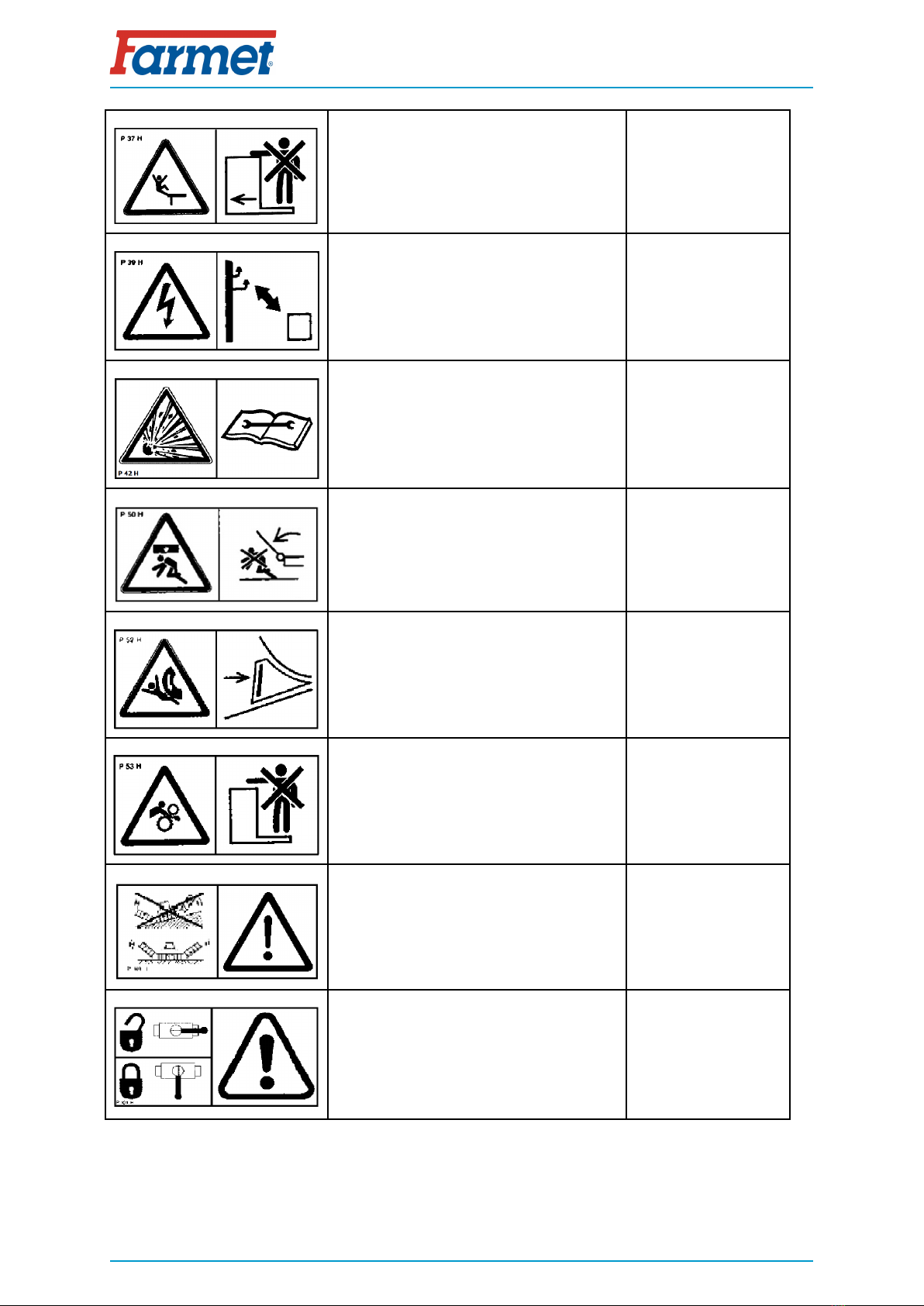
WORK SAFETY LABELS
Travelling and transport on the machine
structure is strictly forbidden. P 37 H
When working and transporting the
machine, maintain safe distance from the
electric appliances P 39 H
The pressure vessel is under gas and oil
pressure. Execute disassembly and repairs
only according to the instructions in the
manual. P 42 H
When folding and unfolding the side frames,
stay outside their reach. P 50 H
Secure the machine against unwanted
movement by positioning on its working
bodies (shares). P 52 H
Stay outside the reach of the tractor -
agricultural machine set, if the tractor
engine is in operation. P 53 H
It is strictly folding and unfolding the side
frames on slopes or inclined surfaces. P 100 H
The shown positions of the lever and the
function of the hydraulic spherical valve
located on the piston rod. P 101 H
13 | 37


15 | 37
DESCRIPTION
6 DESCRIPTION
The machine FANTOM FX 470 NS is structurally solved as carried. It is equipped with a three-point hitch,
TBZ 3. It consists of a central frame and two folding side frames where the tines with chisels in three rows.
The tines are protected against overload with compression springs. The rear frames, equipped with rollers,
are also hung on the frames. A row of spring levellers or flexi-boards can be attached to the rear frames.
The side frames are folded using linear hydraulic motors connected to the external hydraulic circuit.
6.1 Working parts of the machine
1. TPS tractive suspension
2. Machine framework
3. Setting the depth of the rollers
4. Share section in three rows, chisel shares on tines
5. Spring leveller section
6. Rear roller (see chapter 9)

16 | 37
MACHINE ASSEMBLY AT THE CUSTOMER
7 MACHINE ASSEMBLY AT THE CUSTOMER
• The operator must perform the assembly according to the instructions of the producer,
best in cooperation with the expert servicing technician determined by the producer.
• The operator must secure a functional test of all assembled parts after the completion
of the machine assembly.
• The operator must secure that the handling of the machine using lifting equipment during
its assembly is in accordance with chapter „4“.

17 | 37
COMMISSIONING
8 COMMISSIONING
• Before taking over the machine, test and check, whether damage occurred during transport
and whether all parts contained in the bill of delivery were supplied.
• Before commissioning the machine, carefully read this operating manual, especially Chapters
1–5. Before the first use of the machine, familiarise yourselves with its controls and overall
function.
• During work with the machine, observe not only the instructions of this operating manual but
also generally valid regulations of work safety, health protection, fire and transport safety,
and environmental protection.
• The operator must check the machine before every use (commissioning) from the standpoint
of completeness, work safety, work hygiene, fire safety, transport safety, and environmental
protection. A machine showing signs of damage must not be commissioned.
• Aggregation of the machine with the tractor is to be performed on a flat and hardened
surface.
• When working on slopes, observe the lowest allowable slope grade of the set TRACTOR -
MACHINE.
• Before starting the tractor motor, check whether no person or animal is in the working space
of the set and push the warning sound signal.
• The operator is responsible for the safety and all damage caused by the operation of the
tractor and the connected machine.
• The operator is obliged to adhere to the technical and safety regulations of the machine
determined by the producer when working.
• The operator is obliged to retract the working bodies of the machine from the ground when
turning at the headland.
• The operator is obliged to observe the prescribed working depths and speeds stated in the
manual in. chap.1.
• The operator is obliged to lower the machine to the ground and secure the set against
movement before leaving the tractor cabin.
• Lower the machine with caution so that the chisels and shares are not damaged by sharp
lowering to the ground. Position the machine on a flat ground so that the weight of the
machine is evenly transferred to all shares.

COMMISSIONING
8.1 Agregation to a tractor
• The machine can be connected only to a tractor, whose curb weight is identical or higher than
the overall weight of the connected machine.
• The machine operator must observe all generally valid regulations of work safety, health
protection, fire safety, and environmental protection.
• The operator may connect the machine exclusively to a tractor that is equipped with a rear
three-point suspension and a functional undamaged hydraulic system.
• The table of requirements for the towing means for work with the machine:
Requirement for the tractor engine power for the machine
FANTOM FX 470 NS > 160 kW *
Requirement for
the tractor's TPS
Spacing of the lower suspension
joints (measured at the joint axes)
TPS 3
895 ± 1,5 mm
1100 ± 1,5 mm
ø of the hole of the lower
suspension joints for the machine
suspension pivots
37,4 – 37,75 mm
ø of the hole of the upper
suspension joint for the machine
suspension pivot
32 – 32,25 mm
Requirement for
the tractor's
hydraulic system
Side frame folding circuit
Circuit pressure 200 bar, 2 pcs
of quick-coupler sockets ISO
12,5
* Recommended towing means, the real towing force may significantly vary according to the processing
depth, soil conditions, land slope, working body wear and adjustment
• Connect the machine using the TPS suspension bar to the lower arms of the rear TPS of the tractor,
secure the TPS arms using pins against disconnecting
• The machine aggregated with the tractor changes the distribution of the weight to the individual axles of
the tractor. The weight of the front axle is reduced and therefore the controllability gets worse. It also
affects braking properties
When connecting, no persons may stay in the space between the tractor and the machine.
8.2 Hydraulics
• Connect the hydraulics only when the hydraulic circuits of the machine and the tractor
(aggregate) are in a pressure-less condition.
• The hydraulic system is under high pressure. Regularly check for leaks and immediately
remove obvious damage of all lines, hoses, and pipe unions.
• When seeking and removing leaks, use only the suitable tools.
• For connecting the hydraulic system of the machine to the tractor, use the plug (on the
machine) and the socket (on the tractor) of the quick-couplers of the same type. Perform the
connection of the quick-couplers of the machine to the hydraulic circuits of the tractor so that
the folding of the side frames (BLUE and WHITE DUST CAP) is on one control circuit.
In order to prevent accidental or foreign person (children, passengers) caused movement of the
hydraulics, the control switchboards on the tractor must be secured or blocked in the transport
position.
Parts of the hydraulic system of the machine, which are under pressure, are forbidden to
disassemble. Hydraulic oil that penetrates the skin under high pressure causes severe injuries.
In case of injury, seek a physician immediately.
18 | 37

COMMISSIONING
8.3 Folding and unfolding of the machine
• With all hydraulic movements, lower the speed of the moving parts of the machine
before stopping by throttling the corresponding valve at the control unit!
• The hydraulics for the folding and unfolding must be connected to the double-action
control unit.
• The operator must ensure that during folding and unfolding of the side frames, no
person or animal is within their reach (i.e. at the place of their impact) or vicinity and
that no one puts his fingers into the joint space.
• Perform folding and unfolding on flat and solid surfaces or laterally to the slope with the
fully open control unit.
• Only perform folding or unfolding with a machine that is lifted on the suspender of the
tractor.
• Remove stuck soil from folding points, soil may impair function and cause damage to the
mechanics.
• During folding or unfolding, check the side frames and have them continuously fold into
the end position to the stoppers.
Procedure for lowering the machine:
• Remove the securing stoppers located under the lowering joints.
• Lift the machine on the suspender of the tractor.
• Lower the side frameworks smoothly.
• Block or close the controlling unit.
Procedure for unfolding the machine:
• Lift the machine on the suspender of the tractor.
• Unfold the side frameworks smoothly.
• Secure the side frameworks from lifting during work with securing stoppers.
• Block or close the controlling unit.
19 | 37

COMMISSIONING
8.4 Description of the share/chisel replacement
• If the ploughshare / chisel wear is high, this working tool must be replaced
• Tools required for replacement:
• HAMMER
• DRIVER - 12 mm
• The installation is the same for all types of working parts
The machine is sufficiently
lifted so that the working part
can be removed from the
shoe.
Using the prepared tools,
drive the spring pin out and
remove the ploughshare from
the shoe.
Drive a new working part in
the shoe and secure it with
the spring pin 12x50mm.
20 | 37
Table of contents
Other Farmet Tiller manuals


