Vaderstad RAPID RD F Series User manual

Ver.1.3 07/06/01 900107-en
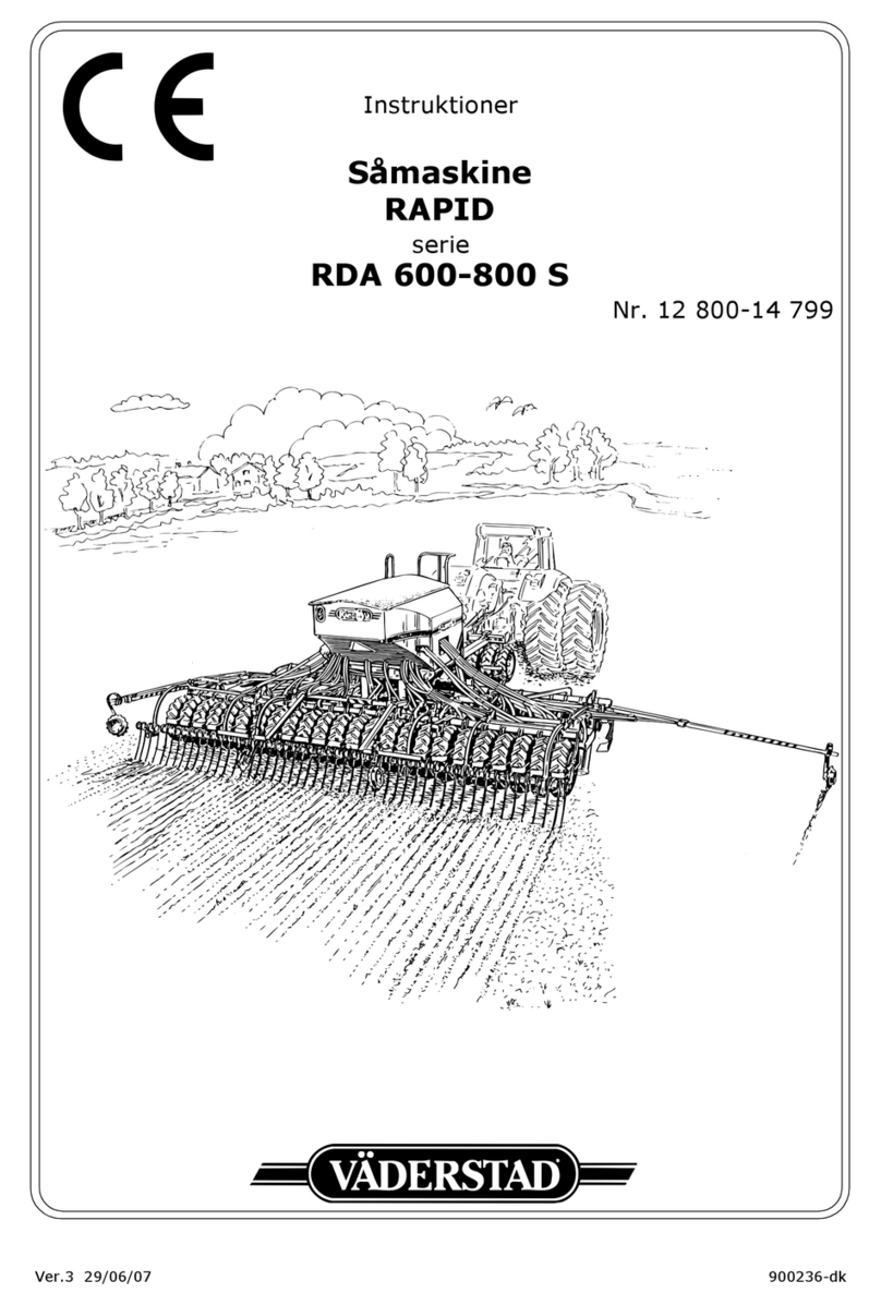
Instructions
Seed drill
RAPID
series
RD 300-450 F
No. 10 026-11 999

2Ver.1.3 07/06/01

Table, Tabelle, Tableau 98-
RD 300-800 F No. 10 000-
Gräs
Grass
Gras
Ray-grass
0,39
Scale Kg/haL= Low gear
-
-
2
3
4
7
10
15
20
25
30
35
Klöver
Clover
Klee
Trèfle
0,77
3
4
5
6
9
15
20
25
35
45
55
60
Raps
Rape
Raps
Colza
0,65
1,5
3
4
5
7
10
15
20
-
-
-
-
2
4
6
8
10
15
20
30
40
50
60
70
Gräs
Grass
Gras
Ray-grass
0,36
Scale Kg/haH= High gear
15
30
45
-
-
-
-
-
-
-
-
-
-
-
Majs
Maize
Mais
Maïs
0,79
35
75
110
150
185
220
260
295
335
370
405
445
480
520
Vicker
Vetch
Vicken
Vesces
0,83
40
80
115
155
195
230
270
310
350
390
425
465
505
540
Lupiner
Lupins
Lupinen
Luping
0,76
35
70
105
140
170
205
240
275
310
345
380
415
450
485
Ärtor
Peas
Erbsen
Pois
0,80
35
75
110
150
185
225
260
295
335
370
410
445
485
520
Bönor
Beans
Bohnen
Fèves
0,85
35
75
110
145
185
220
255
290
330
365
400
440
475
510
Havre
Oats
Hafer
Avoine
0,50
25
50
75
100
125
150
170
195
220
245
270
295
320
345
Korn
Barley
Gerste
Orge
0,67
35
65
100
130
165
200
230
265
300
330
365
400
430
465
Råg
Rye
Roggen
Seigle
0,72
35
70
105
140
175
210
245
280
315
350
385
420
455
490
Vete
Wheat
Weizen
Blé
0,77
35
75
110
145
185
220
255
295
330
365
405
440
475
515
Kg/l
10
20
30
40
50
60
70
80
90
100
110
120
130
140
Hög/High/Hoch/Haut
Låg/Low/Niedrig/Bas
12x100=kg/ha. Utsäde, Cereals, Getreide, Céréales.
26x10=kg/ha. Oljeväxter, Oil seed, Ölpflanze, Plante oléagineuse
Se 3.15. See 3.15. Siehe 3.15. Voir 3.15.
Tag alltid ett utmatningsprov.
Såtabellens innehåll skall endast
ses som riktvärden. Vid små ut-
matningsmängder bör ett nytt ut-
matningsprov tas regelbundet.
Kontrollera körd areal och ut-
matad mängd vid varje påfyll-
ning.
Always make a seed feed test.
The contents of the sowing table
should only be regarded as stan-
dard values. When operating
with small seed quantities a new
seed test should be made regula-
ry. Check driven acreage and
seed feeded quantity at every
time you refill.
Grundsätzlich sollte vor Beginn
des Drillens eine Abdrehprobe
durch- geführt werden. Wenn die
Sorte oder die Fruchtart gewech-
selt wird, muss eine neue Abreh-
probe gemacht werden. Die
Sätabelle ist eine Anhalt und
Hilft bei der Grundeinstellung.
Beim Drillen von kleinen Aus-
saatmengen (z.b. Raps) sollte
eine Abdrehprobe in regelmäßi-
gen Abständen gemacht werden.
Bitte, kontrollieren Sie die be-
stellte Fläche und die ausge-
brachte Menge bei jedem
Nachfüllen des Saatgutes.
Faites toujours un test de dosage.
Les données du tableau ne sont
qu'à titre indicatif. Lors de peti-
tes quantités de dosage, un nou-
veau test de dosage doit être fait.
Contrôlez la superficie travail-
lée et la quantité dosée à cha-
que remplissage.

4Ver.1.3 07/06/01
1 Safety regualtions
1.1 Before using the drill ............................................................................ 8
1.2 Warning decals: .................................................................................. 8
1.3 Other safety precautions ...................................................................... 9
1.4 Location of warning decals on the machine ........................................... 10
1.5 Data plates ....................................................................................... 10
2Assemblyinstructions
2.1 Lifting and unloading the drill .............................................................. 11
2.2 Moving the tool bar tines .................................................................... 12
2.3 Fitting the pre-implements .................................................................. 12
2.4 Fitting the drawbar ............................................................................ 12
2.5 Fitting the drive wheel lifting ram ........................................................ 13
2.6 Fitting a fan ...................................................................................... 13
2.7 Fitting the air hose ............................................................................ 14
2.8 Fitting the PTO shaft .......................................................................... 14
2.9 Fitting the hose bracket ...................................................................... 15
2.10 Installing the Control Box in the tractor ................................................ 17
2.11 Fitting the bout markers ..................................................................... 18
2.12 Fitting the platform ............................................................................ 20
2.13 Fitting the scrapers ............................................................................ 21
2.14 Fitting the following harrow ................................................................. 22
2.15 Fitting the pre-emergence bout marker, mfg. no. -10 309 ....................... 24
2.16 Fitting the pre-emergence bout marker, mfg. no. 10 310- ....................... 26
3 Instructions and settings
3.1 Tractor ............................................................................................. 27
3.2 Hitching the seed drill ........................................................................ 28
3.3 Adjusting hose length and connecting intermediate cable ........................ 29
3.4 Changing between transport position and working position, RD 400-450 F 30
3.5 Horizontal alignment .......................................................................... 32
3.6 Adjusting sowing depth ...................................................................... 33
3.7 Adjusting the wing sections ................................................................ 34
3.8 Adjusting the changeover valve ........................................................... 34
3.9 Adjusting the tool bars ....................................................................... 35
3.10 Setting the seed rate ......................................................................... 36
3.11 Calibration ........................................................................................ 36
3.12 Prior to filling the hopper .................................................................... 38
3.13 Emptying the seed hopper .................................................................. 40
3.14 Operation test ................................................................................... 40
3.15 Adjusting the air-flow ......................................................................... 42
3.16 Electronic Control Box ........................................................................ 51
3.17 Tramlining ........................................................................................ 64
3.18 Adjusting the following harrow ............................................................ 65
3.19 Adjusting Low lift height ..................................................................... 65
3.20 Folding platform, mfg. no. -10 309 ...................................................... 66
3.21 Locking the lifting rams during service .................................................. 66
3.22 Adjusting the seed coulters ................................................................. 67
3.23 Scrapers .......................................................................................... 68

Ver.1.3 07/06/01 5
4 Advice on sowing
4.1 Sowing depth .................................................................................... 69
4.2 Checking the seed feed ...................................................................... 70
4.3 Sowing headlands ............................................................................. 71
4.4 Engaging the drill .............................................................................. 71
4.5 Tramlining ........................................................................................ 72
4.6 Bout markers .................................................................................... 72
4.7 Obstructions ..................................................................................... 72
4.8 Turning with Low lift .......................................................................... 72
4.9 Autumn sowing ................................................................................. 73
4.10 Direct drilling .................................................................................... 73
4.11 Ploughless tillage ............................................................................... 73
4.12 Sowing after ploughing ....................................................................... 73
4.13 Spring sowing ................................................................................... 74
4.14 The Väderstad concept - spring sowing - “Till a bit shallower and drill a
bit deeper” ....................................................................................... 74
4.15 The Tolefors concept .......................................................................... 74
4.16 Cultivating silty soils .......................................................................... 75
5 Maintenance and service
5.1 General maintenance ......................................................................... 76
5.2 Seed feed housing and rape brush ....................................................... 77
5.3 PTO shaft, Mfg. No. -10 158 ................................................................ 77
5.4 Fan and fan transmission, Mfg. No. -10 158 .......................................... 78
5.5 Drive wheel transmission .................................................................... 78
5.6 Locking device, RD 400-450 F ............................................................. 78
5.7 Push rod/ push rod ram ...................................................................... 79
5.8 Cleaning ........................................................................................... 79
5.9 Storing the drill ................................................................................. 80
5.10 Lubrication points .............................................................................. 80
5.11 Changing discs .................................................................................. 81
5.12 Changing disc bearings ...................................................................... 81
5.13 Changing seed coulter mounting bolts .................................................. 82
5.14 Changing wheels ............................................................................... 82
5.15 Changing the seals on the hydraulic rams ............................................. 83
5.16 Changing the valve seals on the lifting ram ........................................... 84
5.17 Repairing and replacing seed hoses ...................................................... 85
5.18 PTO driven hydraulic fan, mftg. no. -10 949 .......................................... 86
5.19 PTO driven hydraulic fan, mftg. no. 10 950- .......................................... 88
6 Troubleshooting
6.1 General information on troubleshooting ................................................ 90
6.2 Troubleshooting list ........................................................................... 91
6.3 Notes on troubleshooting .................................................................... 97
7 Appendices
7.1 Sowing table ................................................................................... 100
7.2 Calibration Results ........................................................................... 101
7.3 Hydraulic diagram ........................................................................... 102
7.4 Electrical diagram ............................................................................ 108
7.5 Connector, mftg. no. 10950 - ............................................................ 111
7.6 Technical data ................................................................................. 113

6Ver.1.3 07/06/01

RD 300-450 F
Ver.1.3 07/06/01 7
IMPORTANT!
This instruction manual is based on experience and results obtained during development of
the Rapid series of drills. Hints and guidelines are to be regarded as general advice, entail-
ing no responsibility whatsoever on the part of Väderstad-Verken AB and/or its represen-
tative. All responsibility for usage, road transport, maintenance and repair etc. of the drill
rests with the owner/driver.
Local conditions affecting crop sequence, soil type, climate etc. may require procedures
different to those mentioned in this manual.
The owner/driver is solely responsible for using the drill correctly in every respect.
Väderstad drills are subjected to thorough quality assurance inspection and function test-
ing before delivery. The user/purchaser shall retain sole liability for ensuring that the
equipment is functioning correctly when in use. Väderstad-Verken AB shall not be liable
for any claims for indirect or consequential damages relating to losses incurred in connec-
tion with the use of the drill. Väderstad-Verken AB accepts no liability for losses arising
from incorrect use of the drill, including its depth control and seed dosage equipment.
Please refer to ”4.1 Sowing depth” on page 69 and ”4.2 Checking the seed feed” on page
70 in this manual.
DECLARATION OF CONFORMITY 89/392/EEC
Väderstad-Verken AB, Box 85, 590 21 Väderstad, SWEDEN
DECLARE
That drills as below conform to the basic safety regulations
in EU guidelines 89/392/EEC and addition.
RD 300 F, RD 400 F and RD 450 F with manufacturing number 10 026 - 14 500.
Gert Gilstring

Safety regualtions
8Ver.07/06/01 07/06/01
1 Safety regualtions
1.1 Before using the drill
Figure 1.1
!Always pay extra attention to paragraphs or figures bearing the following symbol:
!Learn to handle the drill correctly and with care. The drill can be dangerous in inexperienced
or careless hands.
1.2 Warning decals:
Figure 1.2
ARead the instructions carefully and make sure you understand them.
BAlways make sure that the entire working area and folding area of the seed drill are unobstruc-
ted. RD 400-450 F: Never walk under a suspended section. Always check that the automatic
catches have engaged in connection with transport and parking. To ensure reliable operation
of the automatic lock, grease the locking bars periodically.
CWarning tape, pay attention to the danger of crushing and impact injuries. Also used on safety
components.
DNever work under the seed drill when carrying out service or maintenance without ensuring
that the machine is properly supported on stands or is standing on some other firm surface. Se-
cure the lifting ram and the push rod ram (1, accessory) by means of the yellow locking device.
See also ”3.21 Locking the lifting rams during service” on page 66.
A
CD
B
I
EF
H
G

RD 300-450 F
Ver.1.3 07/06/01 9
EDrill with PTO driven fan: Pay attention to the rotating transmission shaft. Do not stride
across or stay close to the rotating transmission shaft. Keep the shaft and the protectors in pro-
per condition. Carefully read the instruction handbook supplied with the transmission shaft.
Drills with a PTO driven hydraulic pump: Pay attention to the rotating transmission for the
hydraulic pump. Do not stride across or stay close to the rotating parts. Disconnect the trans-
mission, switch off the ignition of the tractor and take out the key whenever work close to the
hydraulic pump or other maintenance work is required. Do not use the protective cone as a
stepping board.Make sure the protective cone is securely attached to the hydraulic pump. If the
protective cone is damaged, be sure to replace it immediately. Always secure the hydraulic
pump in the top rod mount on the tractor.
FAlways ensure that the working area of the bout markers is unobstructed. Bear in mind the
danger of injury when folding or unforlding the bout markers or getting caught between the
seed drill and the bout markers when they are folded in. NOTE! The bout markers are always
folded in when the machine is raised, regardless of the indication on the control box. The mar-
ker arm will always fold as the machine is lowered. Therefor always shut off the control box
main switch when the machine is not on the field. All settings will remain unchanged though
the box is shut off. RD 300 F: Always secure the bout markers with the yellow locking device
when the machine is not on the field.
GDo not climb onto the wheels when the seed drill is parked as they can rotate.
HDo not stand on the seed drill while it is in use. Do not stand on the seed hopper grating (ac-
cessory) unnecessarily as there is a danger of falling. WARNING! Since talc is used in con-
nection with pea seeding, for instance, the grating could be extremely slippery.
IDo not stand on the seed drill during front loading of seed.
1.3 Other safety precautions
!Observe the greatest caution when transporting the seed drill on a public road. If the machine
has a full hopper, note that the towed weight is considerable and that the view to the rear is
greatly restricted. Check the adjustment of the tractor's rear-view mirrors. The owner/driver is
solely responsible when the machine is transported on a public road.
!NOTE! This machine/equipment together with its tyres is designed for a maximum speed of
30 km/h, during transportation on the road.
!When any repair work is carried out on the hydraulic system, the seed drill should be in the
lowered position (RD 400-450 F) and resting on a firm and level surface with the wing sections
lowered!
!If the seed drill is folded when parking, the stop device on the master ram should be set so that
the seed drill rests both on its wheels and the discs. Since the weight on the supporting leg is
so high, the machine shall not be parked on loose surface!
!Always make sure that the seed drill's male couplings and the tractor's female couplings are
clean and free from impurities before connecting them together.
!Always use genuine Väderstad spare parts to maintain the quality and reliability of the seed
drill. If other brands of spare parts are used, all guarantee and claim commitments cease to be
valid.

Safety regualtions
10 Ver.07/06/01 07/06/01
1.4 Location of warning decals on the machine
Figure 1.3
1.5 Data plates
1.5.1 Serial number plate
Figure 1.4
AModel number
BManufacturing Number. Always state this number in connection with orders of spare parts, ser-
vice or warranty claims.
1.5.2 CE plate
Figure 1.5
CWorking width
DTransport width
ESerial (CE) number
FWeight: unladen weight incl. following harrow and single Crossboard. For further information
see ”7.6 Technical data” on page 113.
GYear of manufacture
A,B,H,I
E
D
DC
C
F
G
C
D
AB
CD EF G

RD 300-450 F
Ver.1.3 07/06/01 11
2 Assembly instructions
On delivery, the drill may be almost fully assembled depending on the method of transport etc.
Use the following instructions where necessary. The drill can also be delivered with extras not co-
vered by these instructions. If in any doubt, contact Väderstad-Verken AB or your dealer.
2.1 Lifting and unloading the drill
Use either pallet forks or lifting straps (not chains) when lifting the drill.
When lifting with pallet forks, lift from the front in the places indicated by the labels.
When lifting using lifting straps, secure them to the centre sections (RD 300 F) or in the folded up
wings (RD 400-450 F) in the placed indicated by the stickers. Use lifting straps at least 6 m long.
NOTE!Never lift the machine in the indicated places if the wings are foldeddown (RD 400-450 F).
Loaders and lifting equipment used to lift the drill should have sufficient margin to manage the
weight of the machine. For weight indications, see ”7.6 Technical data” on page 113. Lift down
the drill and then carry out the remaining unloading and assembly on a firm, level surface.
NOTE!Never walk under a suspended machine.
Figure 2.1 Figure 2.2

Assembly instructions
12 Ver.07/06/01 07/06/01
2.2 Moving the tool bar tines
Figure 2.3
Prior to delivery, two or more tines have been removed from the centre section tool bar to aid lo-
ading and unloading. Check carefully that these tines have been replaced in the correct positions
before attaching the drawbar. The tine fitting must be to the right of the mark when viewed from
the rear.
NOTE!Always check the tine spacing of a new drill on delivery.
2.3 Fitting the pre-implements
Fit the pre-implements as explained in the spare parts manual or, in certain cases, according to the
attached instructions.
2.4 Fitting the drawbar
Figure 2.4
Fit the drawbar to the centre section using the bolts provided. Place the drawbar on the supporting
leg with the towhook about 40-50 cm over the ground. Connect the post of the drawbar to the turn
buckle on the centre section.
Ensure that both ends of the turnbuckle are unscrewed an equal distance. Check that all bolts are
properly tightened.
The horizontal alignment of the drill will be adjusted later, see ”3.5 Horizontal alignment” on
page 32.

RD 300-450 F
Ver.1.3 07/06/01 13
2.5 Fitting the drive wheel lifting ram
Figure 2.5
Fit the drive wheel lifting ram as shown. Raise the drive wheel if the piston rod is fully out. Bolts
(A) must be tightened untilthere is a freeplay of a few millimetres. Check thatthe drive wheel can
be raised and lowered by hand without the lifting ram jamming between the links. Fit the drive
shaft (B) using the R-clips (C). Check that the cross-ties for the driving axle are as straight as pos-
sible. Adjust the length of the axle if necessary.
2.6 Fitting a fan
Figure 2.6
Fit the fan as shown. The front part of the bracket should rest against the weld bead (A).
A

Assembly instructions
14 Ver.07/06/01 07/06/01
2.7 Fitting the air hose
Fit the ejector elbow on the seed housing. Twist the elbow in well towards the centre of the drill
so that there is sufficient room for the rate test bag.
2.8 Fitting the PTO shaft
Figure 2.9
(Only applicable to machines with a PTO-driven fan.)
Position the tractor and drill at the maximum turning angle without connecting the PTO shaft. If
the power outlet is not central, position the tractor to the side giving the shortest shaft length. Me-
asure up the shaft length (10 cm shorter) and cut the shaft if necessary. Cut both ends equally. Fit
and check the shaft length. The minimum insertion length for the shaft is 500 mm.
NOTE!During operation, the 80omaximum operating angle of the front universal joint must not
be exceeded.
Figure 2.7 Figure 2.8

RD 300-450 F
Ver.1.3 07/06/01 15
2.9 Fitting the hose bracket
Figure 2.10
Fit the hose bracket on the fan.
Connect the fan transmitter and area meter to the cable harness. The cables are numbered and the
corresponding number is on the cable harness.
Attach the outer tubing on the area meter cable to the hydraulic hoses so that the control box can-
not fall down and get damaged on the drill frame.

Assembly instructions
16 Ver.07/06/01 07/06/01

RD 300-450 F
Ver.1.3 07/06/01 17
2.10 Installing the Control Box in the tractor
Figure 2.11
Mount the Control Box securely using the screws on the back of the Box. Place the Box so that it
is clearly within the range of vision of a forward-facing driver.
NOTE!Check for hidden cables before drilling holes in the tractor cab.
Connect the cables: Brown to positive (+) and blue to earth (-).
NOTE!The polarity must not be reversed. If the tractor has an electric socket in the cab, use this.
If there is no socket, connection must be made using an extra cable, preferably 6 mm2.Do not use
a cigarette lighter socket as the current requirement may be as high as 20 A. It is important to
make a secure connection since poor contact will cause malfunction.
Make sure that the connecting cable to the drill is not trapped under the rear window of the tractor
as this may cause damage. Use a hatch or a hole. Clamp the cable securely onto the tractor to pro-
tect the Control Box from damage if the driver forgets to unscrew the connecting cable when un-
hitching the drill.
NOTE!Ensure that the Control Box is switched off until the bout markers are fitted.
2.10.1 RD 400 - 450 F
The drill can now be unfolded. Check that the Control Box is switched off.
NOTE!The following harrow and bout markers etc may be secured to the wheels or the platform
during transport and must be released before unfolding.
Before unfolding, see ”3.4 Changing between transport position and working position, RD 400-
450 F” on page 30.
Unfolding must always be performed with the drill fully raised. Release the
locking devices before unfolding.

Assembly instructions
18 Ver.07/06/01 07/06/01
2.11 Fitting the bout markers
Figure 2.12
2.11.1 RD 400-450 F, -10 949
Drive out the pin (A) from the marker shaft and dismount the cirplip (K). Raise the marker and
introduce the upper end (B) of the marker shaftinto the upper mounting lug (C). Lower the marker
and introduce the lower end (D) of the marker shaft into the lower mounting lug (E). Raise the
washer (F) on the upper end of the marker shaft towards the mounting lug (C) and drive in the pin
(A) under the washer. Fit the circlip (K) again. Fold out the bout marker and release the marker
ram.
Switch on the control box and turn the left-hand multiple selector until the correct marker lamp
lights up. Lower the seed drill hydraulically to move the ram outwards slightly. Then fit the piston
rod to the bout marker by means of the turned M16 bolt (G). Fit a rubber washer (I) on each side
of the piston rod inside the mounting lugs. Raise the seed drill and check that the bout marker en-
ters on or slightly above its catch. Fit the other bout marker in the same way.

RD 300-450 F
Ver.1.3 07/06/01 19
2.11.2 RD 400-450 F, 10 950-
Figure 2.13
Fit the bout marker arm (A) in the wing bracket (B).
Fold in the bout marker arm and check that the catch of the arm (C) fits against the roller (D) on
the wing. If necessary, adjust the bout marker arm height with the stop screw (E).
Fold out the marker a little. Switch on the control box and turn the bout marker selector until the
correct bout marker indicator lights. Lower the machine using the hydraulics in order that the ram
extends a bit. Test fit the piston rod on the bout marker. Verify that the bout marker arm passes
across the roller, but is not under tension when folded in. Also verify that the bout marker arm is
not affected by the post-harrow linkage when it is raised or lowered. If necessary, adjust the ram
length by screwing the piston rod (F) using a key handle/nuts.
Lock the linkage head using a locking nut.
Fit the other bout marker in a similar fashion.
2.11.3 RD 300-450 F
Check the position of the marker tine (H). The distance (L) from the centre of the seed drill to the
tip of the marker tine should be 3.0 m on the RD 300 F, 4.0 m on the RD 400 F, and 4.5 m on the
RD 450 F.
NOTE!Bear in mind the danger of injury when the bout marker is operated. Always make sure that
the marker's operating area is unobstructed!
A
B
E
C
D
F
I
H
L

Assembly instructions
20 Ver.07/06/01 07/06/01
2.12 Fitting the platform
2.12.1 Installing the rear platform (mfg. no. -10 309)
Figure 2.14
Fit the platform, ladder and handrails.
Ensure that the brackets (A) are fitted parallel to each other when they are attached to the platform
(B). Adjust the stop screws (C) so that the brackets (A) rest very lightly on the R-clips (D) when
there is no load on the platform.
2.12.2 Installing the front platform (mfg. no. 10 310-)
Figure 2.15
Install the outer end plates in the installation holes on the hopper.
Install the platform on the outer end plates. The angled corner (A) of the platform should be out-
side the outer end plate (B).
Install the guard rails and the ladder.
B
A
This manual suits for next models
2
Table of contents
Other Vaderstad Tiller manuals
Popular Tiller manuals by other brands

Troy-Bilt
Troy-Bilt VersaTiller 12168 owner's manual

Troy-Bilt
Troy-Bilt 12097 owner's manual

Craftsman
Craftsman 917.297013 owner's manual

Husqvarna
Husqvarna TF545P Operator's manual

STERWINS
STERWINS A061003 Assembly, Use, Maintenance Manual

Meccanica Benassi
Meccanica Benassi MTC 601 Use and maintenance manual