Farmet FALCON 3 User manual
web: www.farmet.cz
e-mail: farmet@farmet.cz
IČ: 46504931
DIČ: CZ46504931
Farmet a. s.
Jiřinková 276
552 03 Česká Skalice, CZ
telefon: +420 491 450 111
fax: +420 491 450 136
GSM: +420 774 715 738
OPERATING MANUAL
FALCON
3| 4| 6| 8
Edition: 7 | effective from: 1.7.2020

Manual
FALCON 3 | 4 | 6 | 8
2 │99
Dear customer,
The FALCON disc sowing machines are high-quality products by Farmet a.s. Česká Skalice.
You can start to fully use the qualities of your machine after you have thoroughly studied the operating
manual. The serial number of the machine is imprinted on the production label and recorded in the operating
manual. Please use this serial number whenever you order spare parts in case of a repair. The production label
is located on the central frame near the pole.
Use only spare parts for these machines according to the Spare Part Catalogue officially published by the
producer, the company Farmet a.s. Česká Skalice.
Possibilities of Use of Your Machine
The disc sowing machines are intended for areal sowing with the option to sow broad-line cultures into
strips. The sowing machine is intended for sowing a wide range of farming products, such as cereal, pulses, oil
bearing crops, clover crops, grass etc. The actual conditions for sowing individual farming products are stated
below. The machine is intended for aggregation with tractors with the output from 90kW, 117 kW, 161 kW and
from 205 kW according to the soil conditions and depth of sowing. The optimal working speed is 10 - 20 km/hour.
The machine allows additional fertilising by granulated fertilisers while sowing.
Production label of the machine FALCON 3
Production label of the machine FALCON 4
Production label of the machine FALCON 6
Production label of the machine FALCON 8
FALCON 3
FALCON 4
FALCON 6
FALCON 8

Manual
FALCON 3 | 4 | 6 | 8
3 │99
CONTENT
1QUICK START .................................................................................................................................................. 5
2CRITICAL PARAMETERS OF THE MACHINE ..................................................................................................... 7
3TECHNICAL PARAMETERS............................................................................................................................... 7
Safety warning................................................................................................................................................... 9
A. GENERAL INSTRUCTIONS FOR USE ................................................................................................................. 9
Protective equipment...................................................................................................................................... 10
B. TRANSPORTING THE MACHINE .................................................................................................................... 10
C. MANIPULATING THE MACHINE BY LIFTING EQUIPMENT............................................................................. 10
D. TRANSPORTING THE MACHINE ON GROUND COMMUNICATIONS.............................................................. 10
E. WORK SAFETY LABELS .................................................................................................................................. 11
4DESCRIPTION OF THE MACHINE................................................................................................................... 14
4.1 Working parts of the machine ............................................................................................................. 14
5ASSEMBLY OF THE MACHINE AT THE CUSTOMER’S SITE ............................................................................. 17
6PUTTING INTO OPERATION .......................................................................................................................... 17
6.1. Aggregation to the tractor ................................................................................................................... 18
6.2. Connecting the hydraulics.................................................................................................................... 19
6.3. Hydraulic diagram of the machine....................................................................................................... 20
6.4. Connecting the elektronic unit............................................................................................................. 21
6.5. Connecting the hydraulic motor of the fan.......................................................................................... 23
6.6. Proper connection to the tractor......................................................................................................... 24
7. ELECTRONIC SYSTEM OF THE MACHINE....................................................................................................... 26
7.1. Turning the sowing on and off ............................................................................................................. 27
7.2. Description of machine control by Müller electronics......................................................................... 28
7.3. Description of the basic display ........................................................................................................... 28
7.4. Controlling hydraulics .......................................................................................................................... 29
7.5. Rail lines setting system ....................................................................................................................... 32
7.6. Reference data..................................................................................................................................... 40
7.6.1 Creating an order......................................................................................................................... 40
7.6.2 Levels of seeds in the hopper ...................................................................................................... 41
7.7. Setting passage sensors ....................................................................................................................... 41
7.7.1 Seeding sensors diagnostics ........................................................................................................ 44
7.7.2 Switching off the seed flow system sensor.................................................................................. 44
7.7.3 Designation of motors and dosers............................................................................................... 45
8. UNFOLDING AND FOLDING MACHINE.......................................................................................................... 45
8.1. Unfolding the machine......................................................................................................................... 46
8.2. Folding the machine............................................................................................................................. 48
9. LOWERING AND LIFTING .............................................................................................................................. 50
10. FILLING UP THE SEED/FERTILIZER CONTAINER............................................................................................. 50
11. SETTING THE FILLED SEEDS/FERTILIZER........................................................................................................ 51
12. SETTING OF THE SOWING BATCH................................................................................................................. 52
12.1. Screw dispecer for side dressing.......................................................................................................... 61
12.2. Setting the fine seeds sowing............................................................................................................... 62
13. SETTING VENTILATOR SPEED ACCORDING TO SEEDS................................................................................... 63
14. ADJUSTMENT OF THE WORKING PARTS OF THE MACHINE ......................................................................... 64
15. ADJUSTING THE MACHINE WORK DEPTH..................................................................................................... 64
15.1 Adjusting the machine by tps arms of the tractor ............................................................................... 65
15.2 Setting the sowing depth ..................................................................................................................... 66
15.3 Setting the down pressure of the sowing bodies................................................................................. 67
15.4 Setting the leveller behind the seed boots .......................................................................................... 69
15.5 Adjusting the working depth of the front section................................................................................ 70
15.6 Adjusting of the levelling...................................................................................................................... 73
15.7 Setting of the markers.......................................................................................................................... 74
15.8 Setting of the deep fertilizing disc........................................................................................................ 75
16. ERRORS ......................................................................................................................................................... 76
17. COMPLETION OF SOWING............................................................................................................................ 88
18. MAINTENANCE AND REPAIRS OF THE MACHINE.......................................................................................... 90
18.1. Replacement of worn discs ................................................................................................................. 90
18.2. Maintenance plan ................................................................................................................................ 91

Manual
FALCON 3 | 4 | 6 | 8
4 │99
18.3. Machine lubrication schedule.............................................................................................................. 95
18.4. Manipulation with lubricans ................................................................................................................ 95
18.5. The pressure in the tyres ..................................................................................................................... 96
18.6. Recommended tightening torques of bolting ...................................................................................... 97
19. STORING THE MACHINE ............................................................................................................................... 97
20. PROTECTION OF ENVIRONMEN.................................................................................................................... 97
21. DISPOSAL OF THE MACHINE AFTER THE END OF ITS USABLE LIFE ............................................................... 97
22. MAINTENANCE AND TERMS OF GUARANTEE............................................................................................... 98
22.1. Maintenance ........................................................................................................................................ 98
22.2. Guarantee ............................................................................................................................................ 98

Manual
FALCON 3 | 4 | 6 | 8
5 │99
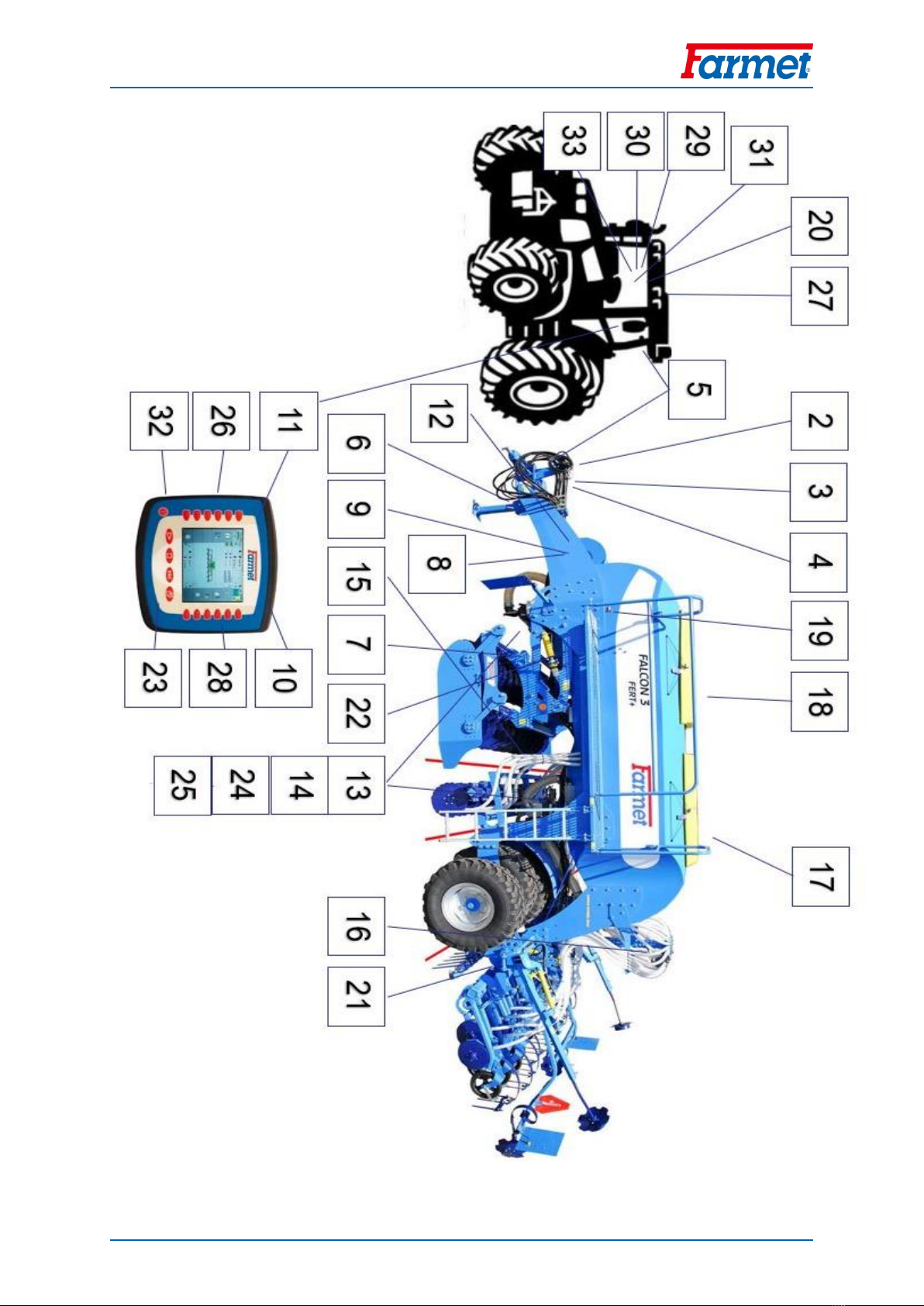
1QUICK START
0
Safety warning
9
1
Pull the Falcon with the pulling device
18
2
Connect the return hydraulic hose
24
3
Connect the other hydraulic hoses
19
4
Connect the 7-pin cable for the road lights of the machine
5
Connect the machine electronics with the pulling vehicle.
21
6
Lift the front supporting leg of the machine and secure it
7
Release the pins for unfolding the front section
46
8
Open the valve for unfolding (blue marking)
46
9
Open the valve for lifting the front preparatory section (yellow marking)
50
10
Use the main switch to switch on the seed drill terminal
11
Unfold the machine using the hydraulic circuit and the control terminal
46
12
Set the pressure using the pressure reducing valve
68
13
Check the seed cleanliness
88
14
Check for leakage of the planer in the seedbed
88
15
Check the flow of the fertilizer hoses
16
Check the seed hose for continuity
17
Pour the seed
50
18
Pour the fertilizer
50
19
Check and adjust the seeder plane
65
20
Set the lower end of the tractor's TPS
65
21
Set the sowing depth
66
22
Adjust the depth of the front section
70
23
Set the dose in the electronics
58
24
Set the value on the doser
52
25
Perform a test shot
59
26
Enter the value of the weighed sample into the terminal
59
27
Check that the seeding speed range displayed on the terminal is optimal: 1.5-20 km/h
59
28
Set sensor sensitivity according to the table in the manual
41
29
Set the priority on the fan's hydraulic circuit
30
Adjust the oil flow for the fertilizer hydromotor
19
31
Set the fan speed, by seed and batch
63
32
Set the required hydraulic functions - indicators, track markers, etc.
30
33
Set the required pressure on the seedbed, depending on the soil conditions (20-60bar).
68
Manual
FALCON 3 | 4 | 6 | 8
6 │99

Manual
FALCON 3 | 4 | 6 | 8
7 │99
2CRITICAL PARAMETERS OF THE MACHINE
The machine is designated for sowing common cereals and broad-line cultures in aggregation with an
agricultural wheel or caterpillar tractor. Another type of use exceeding the determined purpose is forbidden.
(x) The machine is only operated by one person –the tractor driver.
(x) The operator must not use the machine for other purposes, particularly:
(x) For transporting people and animals on the construction of the machine,
(x) For transporting load on the construction of the machine,
(x) Aggregation of the machine with other tractive equipment than stated in Chapter „6.1./P.18“.
3TECHNICAL PARAMETERS
Tab. 1 –Technical parameters of the machine
PARAMETERS
FALCON 3
FALCON 4
FALCON 6
FALCON 8
Working width (mm)
3000
4 000
6 000
8 000
Transport width (mm)
3 000
3 000
3 000
3 000
Transport height (mm)
3 300
3 300
3 300
4 000
Total length of the machine (mm)
7 500
7 500
7 500
7 500
Working depth (mm)
0 –100
0 –100
0 –100
0 –100
Container capacity without fertilization ( l )
4000
4000
4000
4000
Container capacity with fertilization ( l ) (ratio 40 : 60)
6000
6000
6000
8500
Filling height of the container (mm)
2650
2 650
2 650
3 400
Dimensions of the filling opening w/out fertilization (m)
2x0,52 / 1,2x0,52
2x0,52 / 1,2x0,52
2x0,52 / 1,2x0,52
2x0,52 / 1,2x0,52
Number of drill coulters (spacing 125 / 150 mm)
24/20
32 / 26
48 / 40
64 / 52
Number of fertilizer boots (spacing 250 / 300 mm)
12/10
16 / 13
24 / 20
32 / 26
Pressure of drill coulters / fertilizer boots (kg)
50 -115 / až 200
50 -115 / až 200
50 -115 / až 200
50 -115 / až 200
Diameter of the sowing disk, two-disk coulter / press-wheel
(mm)
355 / 340
355 / 340
355 / 340
355 / 340
Diameter of the sowing disk, single-disk coulter / press-
wheel (mm)
410 / 690
410 / 690
410 / 690
410 / 690
Number of discs
490
Front
12
16
25
34
Rear
11
15
24
33
Number of chisels of 2-row section, depth 200mm
(spacing 250 / 300 mm)
12/10
16 / 13
24 / 20
32 / 26
Number of chisels of 3-row section, depth 200mm
(spacing 250 / 300 mm)
12/10
16 / 13
24 / 20
32 / 26
Number of chisels of 2-row section, depth 300mm
(spacing 375 mm)
8
16
24
32
Working capacity (ha/h)
3 - 4,5
4 –6
6 - 9
8 - 12
Pulling vehicle (kW)
92 / 125
117 / 160 *
161 / 220 *
205 / 280 *
Working speed (km/h)
10 –20
10 –20
10 –20
10 –20
Maximum transport speed (km/h)
25
25
25
25
Maximum slope accessibility (°)
6
6
6
6
Tyre dimensions
405/70-20
405/70-20
405/70-20
405/70-20
Type of brakes / distribution 1)
air / two-line***
air / two-line***
air / two-line***
air / two-line***
Required pressure (kPa)
8,5
8,5***
8,5***
8,5***
Number of hydraulic circuits / pressure (bar)
9 / 200
3 / 200
3 / 200
3 / 200
Number of quick-coupling devices / type
5 / ISO 12,5
5 / ISO 12,5
5 / ISO 12,5
5 / ISO 12,5
Non-pressure return line (max. 5 bar)
1 / ISO 20
1 / ISO 20
1 / ISO 20
1 / ISO 20
Hydraulic fan oil flow ( l/min)
30 - 40
30 - 40
30 - 40
30 - 40
Oil flow for machine control (l/min)
50 - 60
50 - 60
50 - 60
50 - 60
Electric system requirement
12 V DC / 40 A
12 V DC / 40 A
12 V DC / 40 A
12 V DC / 40 A
Tractor suspension requirement
TPS kat. 3
TPS kat. 3
TPS kat. 3
TPS kat. 3
Machine weight without fertilization (kg)
4 830 –5840**
5 340 –6 580**
6 800 –8 000**
8 440 –9 950**
Machine weight with fertilization (kg)
5 630 –6140**
6 630 –8 420**
8 000 –9 860**
9 600 –12 100**
* recommended pulling vehicle, the actual pulling force may significantly change according to the selected version of the machine, processing depth, soil
conditions, inclination of land, wear and tear of the working parts and their adjustment
** weight of the machine according to accessories
*** hydraulic brake alternative / operating pressure 130±5 bar
Technical Advice!
1) Transport/Brake System: Follow the national regulations valid for transportation of machines on public roads. Check
the legal provisions valid in the country and regulations on maximum permissible total axle weights and loads and also
on the necessary potential use of a brake system. If you have any further questions, please contact our sales
representative.

Manual
FALCON 3 | 4 | 6 | 8
8 │99
PARAMETERS
FALCON 3 Compact
FALCON 4 Compact
Working width (mm)
3000
4 000
Transport width (mm)
3 000
3 000
Transport height (mm)
2 800
2 800
Total length of the machine (mm)
7 000
7 000
Working depth (mm)
0 –100
0 –100
Container capacity ( l )
3000
3000
Filling height of the container (mm)
2600
2600
Dimensions of the filling opening (m)
0,52x1,92
0,52x1,92
Number of drill coulters (150 mm)
20
26
Pressure of drill coulters / fertilizer boots (kg)
50 -115
50 -115
Diameter of the sowing disk (mm)
355
355
Number of discs
23
31
Working capacity (ha/h)
3 - 4,5
4 –6
Pulling vehicle (kW)
92 / 125
117 / 160 *
Working speed (km/h)
10 –20
10 –20
Maximum transport speed (km/h)
25
25
Maximum slope accessibility (°)
6
6
Tyre dimensions
7,5-16
7,5-16
Type of brakes / distribution 1)
air / two-line***
air / two-line***
Number of hydraulic circuits / pressure (bar)
2 / 210
2 / 200
Number of quick-coupling devices / type
4 / ISO 12,5
4 / ISO 12,5
Non-pressure return line (max. 5 bar)
1 / ISO 20
1 / ISO 20
Hydraulic fan oil flow ( l/min)
30 - 40
30 - 40
Oil flow for machine control (l/min)
30
30
Electric system requirement
12 V DC / 25 A
12 V DC / 25 A
Tractor suspension requirement
TPS kat. 2 a 3
TPS kat. 2 a 3
Machine weight without (kg)
3 800
4 400
* recommended pulling vehicle, the actual pulling force may significantly change according to the selected version of the machine, processing depth, soil
conditions, inclination of land, wear and tear of the working parts and their adjustment

Manual
FALCON 3 | 4 | 6 | 8
9 │99
SAFETY WARNING
A. GENERAL INSTRUCTIONS FOR USE
A.1 (x) The machine is produced in compliance with the latest technological conditions and approved safety
regulations. However, the use of the machine may still cause injuries to the user or third persons or
damage to the machine or occurrence of other material damages.
A.2 (xx) Use the machine only in a technically unexceptionable condition, in compliance with its purpose, with
awareness of potential risks and observance of safety instructions stated in this manual!
The Manufacturer is not liable for damages caused by the use of the machine that is in contradiction with
the limit parameters of the machine (p. 7) and with the instructions for the use of the machine (Chapter
A and 3). The User bears the risk.
Immediately eliminate all defects that could have a negative impact on safety!
A.3 (7) The machine may only be operated by a person authorized by the owner under the following
conditions:
(8) He or she must have a valid driving licence in the relevant category,
(9) He or she must be verifiably informed on the safety rules of working with the machine and must
have command of the operation of the machine in practice,
(10) The machine must not be operated by a minor (minors),
(11) He or she must understand the meaning of warning symbols placed on the machine. Respecting
the symbols is important for a safe and reliable operation of the machine.
A.4 (12) Maintenance and service repairs may only be performed by a person:
(13) Authorized by the owner,
(14) Trained in an engineering field with the knowledge of repairs of similar machinery,
(15) Verifiably informed on the safety rules of working with the machine,
(16) With a driving licence in the relevant category for repairs of the machine attached to a tractor.
A.5 (17) The operator of the machine must ensure safety of other people during the work with the machine and
its transportation.
A.6 (18) During machine work in the field or during transport, the operator must control the machine from the
tractor's cabin.
A.7 (19) The operator may only enter the construction of the machine when the machine is off and secured
against movement only in order to:
(20) adjust the working parts of the machine,
(21) repair and maintain the machine,
(29) release or secure the ball valves of the axle,
(27) secure the ball valves of the axle before tilting the side frame,
(28) adjust the working parts of the machine after opening the side frame.
A.8 (xxx) When climbing onto the machine, do not step on the tyres of the rolls or other revolving parts as they
may roll over and you can seriously hurt yourself if you fall down.
This warning symbol warns against an imminent dangerous situation that
could lead to death or serious injury.
This warning symbol warns against a dangerous situation that could lead
to death or serious injury.
This warning symbol warns against a situation that could lead to a small or
minor injury. It also points out dangerous tasks related to the activity that
could lead to an injury.

Manual
FALCON 3 | 4 | 6 | 8
10 │99
A.9 (22) Any changes or adjustments of the machine may only be performed with a written consent of the
producer. The producer is not responsible for any potential damages occurred as a result of non-
compliance with this instruction. The machine must always be equipped with the prescribed accessories,
equipment and gear including the safety labels. All warning and safety signs must be always legible and
at their positions. They must be replaced if damaged or lost without delay.
A.10 (23) The operating manual and the requirements of the safety at work must be always available to the
operator.
A.11 (24) When operating the machine, the operator must not consume alcohol, medicine, narcotic and
hallucinogenic substances that reduce attention and coordination abilities. If the operator has to take
medicine prescribed by the physician or if he or she uses over the counter medicine, he or she must be
informed by the physician whether he or she is able to reliably and safely operate the machine under these
circumstances.
PROTECTIVE EQUIPMENT
For the operation and maintenance use:
Close-fitting clothing
Protective gloves and goggles for protection from dust and sharp parts
of the machine
B. TRANSPORTING THE MACHINE
B.1 (1) The vehicle intended for the transportation of the machine must have at least the same bearing capacity
as the weight of the transported machine is. The total weight of the machine is stated on the production
label.
B.2 (2) The dimensions of the transported machine including the vehicle must comply with valid regulations
for traffic on ground communications (decrees, acts).
B.3 (3) The transported machine must be always attached to the vehicle so that it cannot be released during
transportation.
B.4 (4) The carrier is responsible for damages caused by the release of incorrectly or insufficiently attached
machine to the vehicle.
C. MANIPULATING THE MACHINE BY LIFTING EQUIPMENT
C.1 (1) The lifting equipment and binding instruments intended for manipulation with the machine must have
at least the same bearing capacity as the weight of the manipulated machine is.
C.2 (2) The machine may only be attached for manipulation in designated places marked by stick-on labels
showing a “chain“.
C.3 (3) When attached (suspended) in designated places, it is not allowed to move in the area of potential reach
of the manipulated machine.
D. TRANSPORTING THE MACHINE ON GROUND COMMUNICATIONS
Transport Position of FALCON
Attach the machine to the tractor by hanging with the use of the two-point suspension equipment
(TPS 3).
The side frames must be folded in the vertical position.
The machine must be equipped with removable shields displaying the boundaries, functional lighting
and a board of rear label for slow vehicles (pursuant to ECE No.69).
The lighting must be turned on when in operation on ground communications.
The tractors must be equipped with a special light appliance with orange colour that must be turned
on when in operation on ground communications.
The operator must drive with increased caution and consideration for other participants of the traffic.
Manual
FALCON 3 | 4 | 6 | 8
11 │99
The operator must secure the arms of the rear TPS of the tractor in the transport position when
operating on ground communications. At the same time, the arms of the rear TPS of the tractor must
be secured against swinging sideways.
It is strictly forbidden to transport people or load on the machine or connect another machine, semi-
trailer or additional equipment to it.
The maximum transport speed during travelling on roads is 25 km/hour.
Ban of transport with decreased visibility!
The machine may only be driven on roads when equipped with air brakes (the customer receives a
certificate of roadworthiness). Otherwise, it is prohibited to drive the machine on roads!
E. WORK SAFETY LABELS
Warning safety labels are used for the protection of the operator.
The following applies generally:
A) Strictly observe the warning safety labels.
B) All safety instructions also apply to other users.
C) If the aforementioned “SAFETY LABEL” located on the machine is damaged or destroyed, THE OPERATOR
MUST REPLACE IT WITH A NEW ONE!!!
The position, appearance and exact meaning of work safety labels on the machine are given in the
following tables (Tab.2/p.11-12) and the picture (Picture 1,2/p.13).
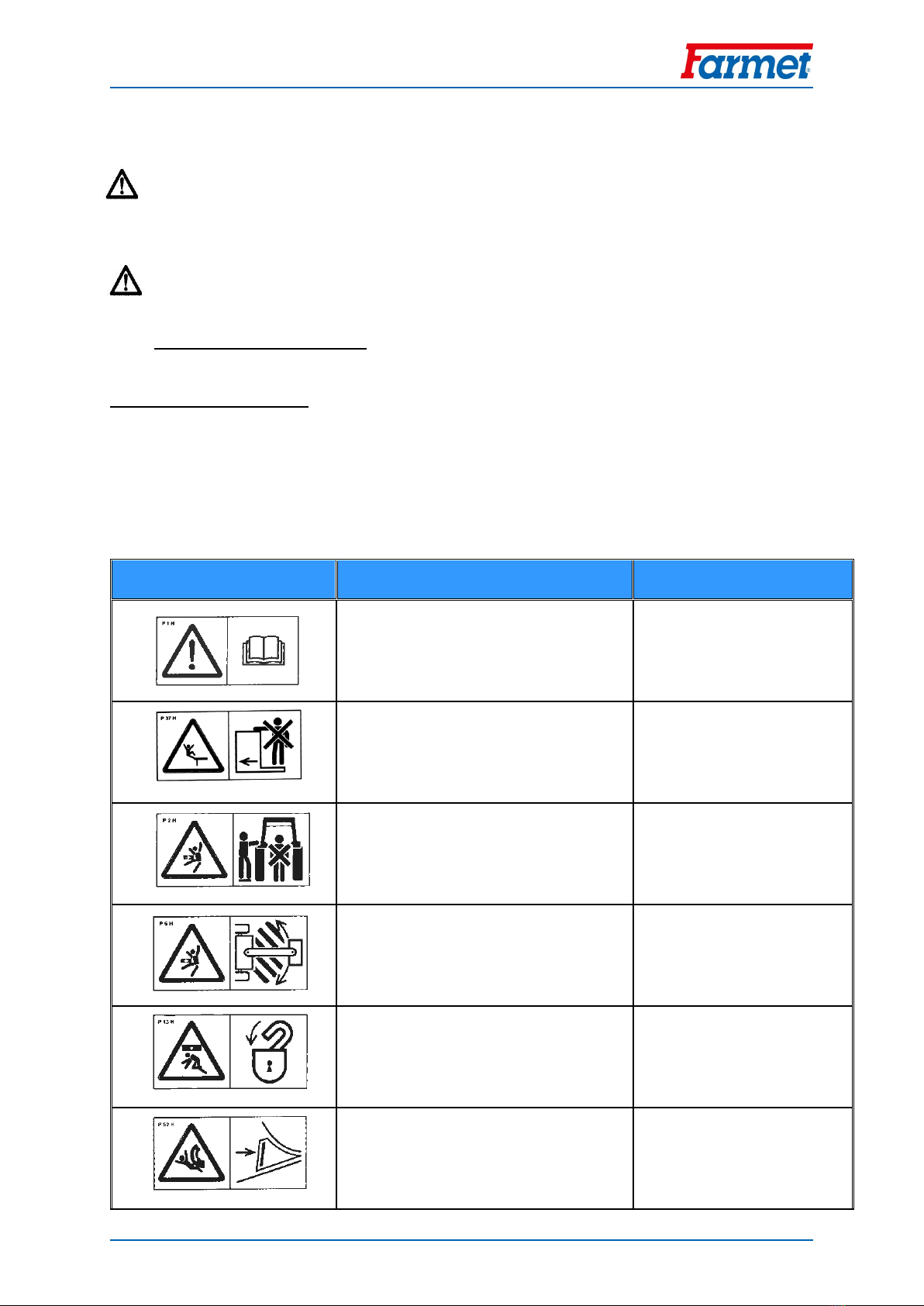
Tb.2 - Self-adhesive warning safety labels located on the machine
WARNING SAFETY LABEL
TEXT TO THE LABEL
POSITION ON THE
MACHINE
Read carefully the operating manual before
manipulation with the machine.
Observe the instructions and safety rules
when operating the machine.
P 1 H
Driving the machine and transportation on
its construction is strictly forbidden.
P 37 H
When connecting and disconnecting, do not
enter the area between the tractor and the
machine. Do not enter that area unless the
tractor and the machine are not moving and
the engine is off.
P 2 H
Stay beyond reach of the set Tractor –
Agricultural Machine when the tractor
engine is running.
P 6 H
Secure the axle of the machine against an
unexpected drop before its transportation.
P 13 H
Secure the machine against unwanted
movement.
P 52 H
Manual
FALCON 3 | 4 | 6 | 8
12 │99
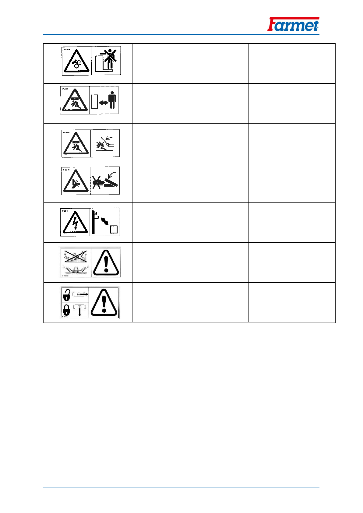
Do not approach the rotary parts of the
machine unless they are standing still, i.e.
they are not rotating.
P 53 H
Stay beyond reach of the lifted machine.
P 4 H
When folding and unfolding the side frames
and service bridge, stay beyond their reach.
P 50 H
When tipping the service bridge, stay beyond
its reach.
P 20 H
When working with the machine as well as
during its transportation, keep a safe
distance from electric appliances.
P 39 H
It is forbidden to fold and unfold the side
frames of the machine on a slope or an
inclined plane.
P 100 H
Pictured positions of the lever and the
hydraulic ball valve function located on the
piston-rod.
P 101 H
Manual
FALCON 3 | 4 | 6 | 8
13 │99
Picture 1
Picture 2
P 100 H
P 101 H
P 1 H
P 2 H
P 6 H
P 20 H
P 50 H
P 39 H
P 37 H
P 4 H
P 39 H
P 37 H
P 4 H
P 50 H
P 37 H
P 52 H
P 53 H
P 20 H
P 50 H
P 13 H
P 20 H
P 20 H
P 52 H
P 53 H
P 50 H
P 37 H
P 39 H
P 37 H
P 4 H

Manual
FALCON 3 | 4 | 6 | 8
14 │99
4DESCRIPTION OF THE MACHINE
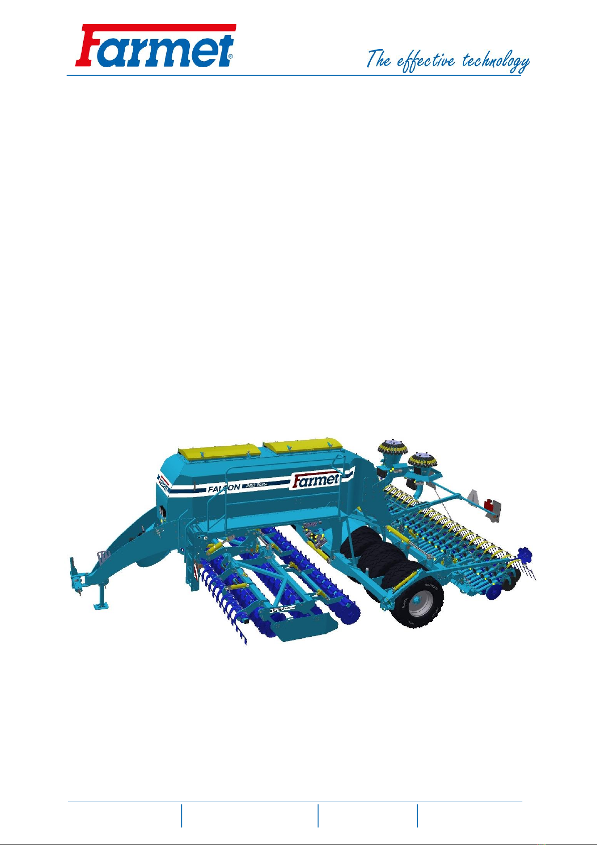
The FALCON disc sowing machine is designed as semi-carried and folding. It is connected to the tractor using
a drawbar with pins of Cat III in the bottom arms of the tractor three-point suspension (TPS). In the front, there
is a preparatory section for soil processing and levelling larger unevenness followed by a pneumatic-tyred
ramming roller that levels and compacts soil in front of the sowing bodies. Then there is a leveller installed in the
axis of each sowing body. At the end there are sowing bodies with compacting wheels and a leveller. Some of
the tyres of the roller are also used for transport in the transport position. The seed container is equipped by a
sowing mechanism commonly used in the standard ACCORD pneumatic sowing machines. There is also possibility
to have Farmet Dispenser (Roller replacement system). The seeds are carried by air flow through seed tubes to
the sowing body where it is placed in the soil in rows. The soil is then compacted by the wheel and levelled out
with the leveller. The seeding mechanism is driven by electric motors. The fan for the transport of seeds is driven
by hydraulic motor from the hydraulic circuit of the tractor. The machine is equipped with central markers and
markers of rail lines. The electronic system of the machine allows checking the functions of the machine,
regulation of the sowing batch and formation of rail lines. The transport wheels may be equipped with pneumatic
brakes or hydraulic brakes.
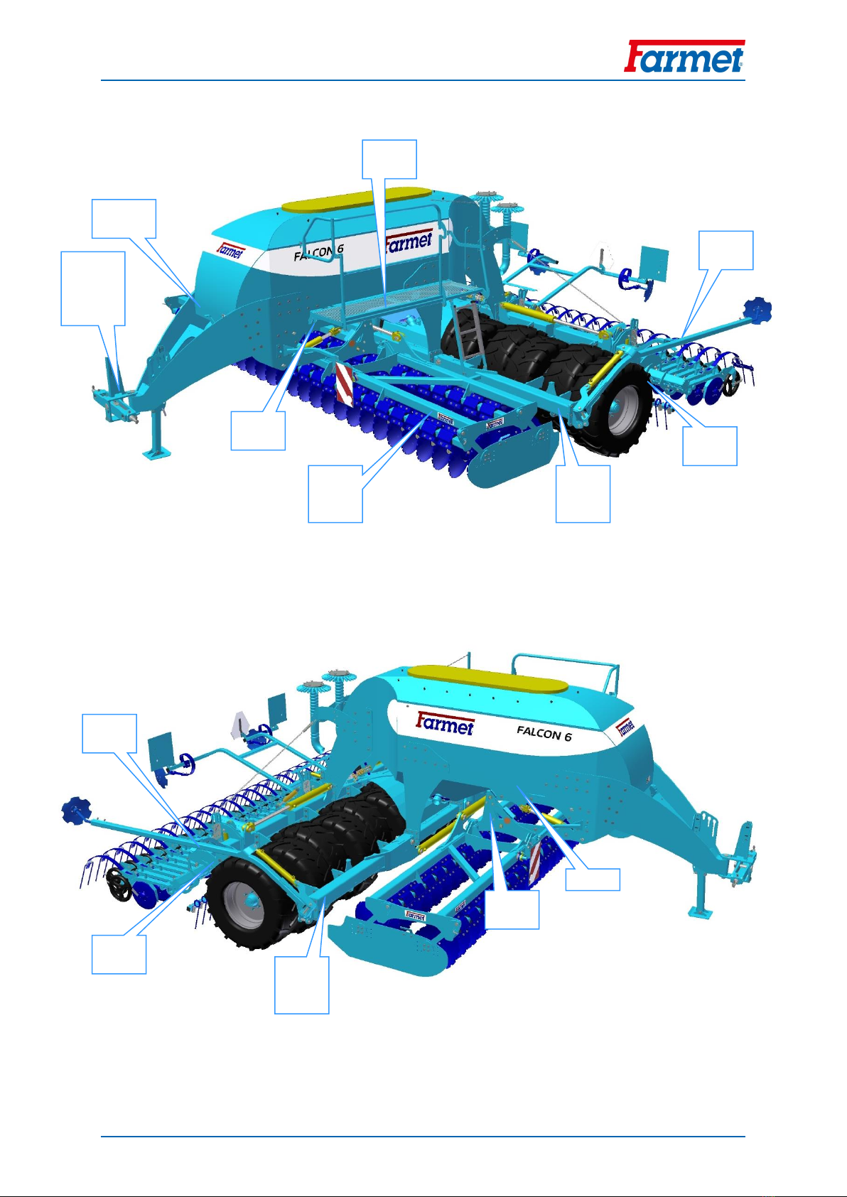
4.1 WORKING PARTS OF THE MACHINE
Picture 3.1 –Working parts of the machine FALCON PRO
4.1.1 Drawbar with a collapsible resting leg 4.1.5 Leveller section
4.1.2 Front preparatory section 4.1.6 Sowing bodies with press-wheels
4.1.3 Disk fertilizing section 4.1.7 Leveller after the sowing bodies
4.1.4 Pneumatic-tyred flotation roller 4.1.8 Markers
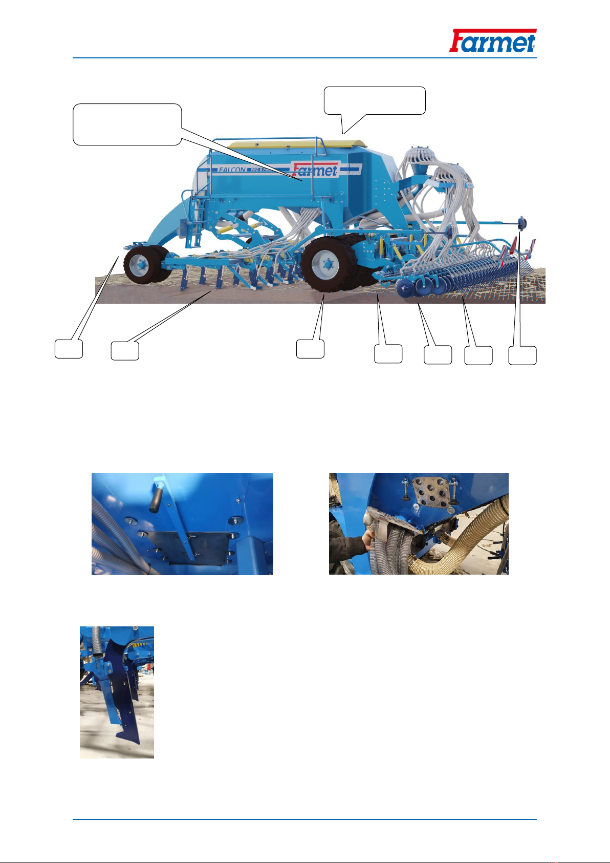
Seed hopper with moveable orifice plate Easy release of fertilizer distribution
Seed / fertilizer
Seed hopper with
moveable orifice plate
4.1.1
4.1.3
4.1.4
4.1.5
4.1.2
4.1.6
4.1.8
4.1.7
Manual
FALCON 3 | 4 | 6 | 8
15 │99
Seed / fertilizer
Seed hopper with
moveable orifice plate
Picture 3.2 –Working parts of the machine FALCON PRO with CHISEL SECTION
4.1.1 Drawbar with a collapsible resting leg 4.1.5 Sowing bodies with press-wheels
4.1.2 Chisel section 4.1.6 Leveller after the sowing bodies
4.1.3 Pneumatic-tyred flotation roller 4.1.7 Markers
4.1.4 Leveller section
Seed hopper with moveable orifice plate Easy release of fertilizer distribution
4.1.2 new replaceable chisel shape
4.1.1
4.1.3
4.1.4
4.1.5
4.1.2
4.1.6
4.1.7

Manual
FALCON 3 | 4 | 6 | 8
16 │99
Seed
Picture 3.3 –Working parts of the machine FALCON COMPACT
4.1.1 Drawbar with a collapsible resting leg 4.1.4 Sowing bodies with press-wheels
4.1.2 Disk section 4.1.5 Leveller after the sowing bodies
4.1.3 Pneumatic-tyred flotation roller 4.1.6 Markers
4.1.1
4.1.3
4.1.4
4.1.5
4.1.2
4.1.6

Manual
FALCON 3 | 4 | 6 | 8
17 │99
5ASSEMBLY OF THE MACHINE AT THE CUSTOMER’S SITE
The owner must execute the assembly according to the producer’s instructions, if possible in cooperation
with a professional service technician determined by the producer.
The owner must execute a functional test of all assembled parts after the completion of the assembly
of the machine.
The owner must ensure that the manipulation with the machine by lifting equipment corresponds with
Chapter „C“.
6PUTTING INTO OPERATION
Before you take over the machine, test and check it for any damages incurred during transportation and
check that all parts included in the delivery note have been delivered.
Before you put the machine into operation, read the operating manual carefully, particularly chapters A-
E p.9-13. Learn about the control elements of the machine and its overall function before the first use.
When working with the machine, observe the instructions in the manual as well as generally valid rules
for the safety at work, protection of health, fire and traffic safety and protection of environment.
The operator must check the machine before every use (putting into operation) for aspects in the field
of completeness, safety at work, work hygiene, fire safety, traffic safety and protection of environment.
If the machine shows signs of damage, it must not be put into operation.
Execute aggregation of the machine with the tractor on an even and compact surface.
When working on slopes, observe the lowest allowable slope accessibility of the whole set TRACTOR –
MACHINE.
Before turning on the engine of the tractor, check that there are no people or animals in the working area
of the set and press the warning sound signal.
The operator is responsible for safety and for all damages caused by the operation of the tractor and the
attached machine.
The operator must observe technical and safety regulations of the machine determined by the producer
when working with the machine.
The operator must lift the machine when turning at the plough turning end, i.e. the working parts must
not be in the ground.
The operator must observe the prescribed working depths and speeds set in the instructions for use in
Tab. 9/p.64 when working with the machine.
The operator must lower the machine to the ground and secure the set against movement before leaving
the cabin of the tractor.

Manual
FALCON 3 | 4 | 6 | 8
18 │99
6.1. AGGREGATION TO THE TRACTOR
The machine may only be connected to a tractor whose standby weight equals or is higher than the total
weight of the attached machine.
The operator must observe all generally valid regulations for the safety at work, protection of health, fire
safety and protection of environment.
The operator may only attach the machine to a tractor which is equipped with a rear three-point
suspension (TPS) and a functional undamaged hydraulic system.
The table with the requirements for the tractive instrument for work with the machine:
Tab.3
(5) Requirement for the engine power of the tractor for FALCON 3
90 kW*
(5) Requirement for the engine power of the tractor for FALCON 4
117 kW*
(5) Requirement for the engine power of the tractor for FALCON 6
161 kW*
(5) Requirement for the engine power of the tractor for FALCON 8
205 kW*
(6)Requirement for TPS of the tractor
(7)distance of the bottom suspension
hinges (at the axes of the hinges)
1010±1,5 mm,
(can be also set to 910±1,5 mm)
(8)holes of the bottom suspension
joints for the suspension hinge pins of
the machine
37,5 mm
(9)Requirement for the hydraulic system
of the tractor
(x)circuit of the electric distributor
(14)Pressure in the circuit
min.190 bar –max.230
60 l/min., 2 sockets for snap
coupling ISO 12.5
(19)circuit of the hydraulic engine
(20)Pressure in the filling branch
min.130 bar–max.230 bar, 1
socket for snap coupling ISO
12.5
(21)Pressure in the waste branch
max.3 bar, 1 socket for snap
coupling ISO 20
(x)down-pressure of the sowing bodies
(14)Pressure in the circuit
min.190 bar –max.230
10 l/min., 1 sockets for snap
coupling ISO 12.5
(x)circuit of lifting and lowering the
preparatory section
(14)Pressure in the circuit
min.190 bar –max.230
40 l/min., 2 sockets for snap
coupling ISO 12.5
(12)Requirement for the air system of the
tractor (if the machine is equipped with
brakes)
(13) circuit of braking of the machine
axle
(16)Pressure in the circuit min.6
bar –max. 15 bar, 1 clutch head
for single circuit brakes
(x)Requirement for the electric system of
the tractor *
(x) connection of the electronic system
of the machine
12V / 40 A
+ red
-black
Connect the machine with the carrier bar TPS to the lower arm of the tractor TPS and secure the TPS arms
with pegs against disconnection.
When connecting the machine, there must not be any people in the area between the machine
and the tractor.

Manual
FALCON 3 | 4 | 6 | 8
19 │99
6.2. CONNECTING THE HYDRAULICS
Connect the hydraulics only if the hydraulic circuits of the machine and the tractor (aggregate) are without
any pressure.
The hydraulic system is under great pressure. Check regularly for leakages and immediately eliminate any
visible damage to all distribution, tubes and screw joints.
When checking for and eliminating leakages, use appropriate equipment.
Use the plug (on the machine) and the socket (on the tractor) of the same type of snap coupling when
connecting the hydraulic system of the machine to the tractor. Execute the connection of the snap
coupling of the machine to the hydraulic circuits of the tractor according to Tab. 4.
Tab. 4 - Connection of the hydraulic circuits and setting up the flow of oil
Circuit
Plug
Cover colour
Oil flow direction
Flow of oil
Hydraulic motor of the fan
ISO 12,5
red
pressure tube
20 –40 l/min
ISO 20
black
open waste
Controls of the machine
hydraulics
ISO 12,5
blue
pressure tube
50 –60 l/min
ISO 12,5
blue
reverse tube
Hydraulic drift drive
ISO 12,5
green
pressure tube
10 –15 l/min
Micro drill
ISO 12,5
black
pressure tube
15 –20 l/min
Flexi boards
ISO 12,5
white
pressure tube
15 –20 l/min
ISO 12,5
white
reverse tube
15 –20 l/min
Lifting the front section
ISO 12,5
yellow
pressure tube
20 –40 l/min
ISO 12,5
yellow
reverse tube
In order to rule out unintentional movement of the hydraulics or movement caused by third persons
(children, passengers), the controlling distributors in the tractor must be secured or blocked and the
controlling unit switched off if the machine is not used or if it is in the transport position.
The parts of the hydraulic system of the machine that are under pressure must not be disassembled.
The hydraulic oil causes serious injuries when it penetrates the skin under the high pressure. In case of injury,
immediately seek a doctor.

Manual
FALCON 3 | 4 | 6 | 8
20 │99
6.3. HYDRAULIC DIAGRAM OF THE MACHINE
This manual suits for next models
5
Table of contents
Other Farmet Tiller manuals


Popular Tiller manuals by other brands


SNOWJOE
SNOWJOE Sunjoe 24V-TLR-CT Operator's manual

Poulan Pro
Poulan Pro 96092001501 Illustrated parts list

Homelite
Homelite 24666 Instructions-parts list

Craftsman
Craftsman 293410 Repair parts manual

Gardol
Gardol GLV 1200-31 Original operating instructions

Craftsman
Craftsman INCREDI.PULL 316.299371 Operator's manual


