Farmet FANTOM 1050 PRO User manual
FANTOM
11005500 PPRROO |11225500 PPRROO
Edition: 2Effective from: 1.7.2019
FARMET a.s.
Jiřinková 276
552 03 Česká Skalice, CZ
phone: +420 491 450 111
fax: +420 491 450 136
GSM: +420 774 715 738
IČ: 46504931
DIĆ: CZ46504931
www.farmet.cz
e-mail: [email protected]
OPERATING MANUAL
FFAANNTTOOMM
11005500 PPRROO |11225500 PPRROO

2 | 59
Prepared by: Technical Department, Farmet a.s.
on 11.7.2019, changes reserved
PREFACE
3 | 59
PREFACE
Dear customer,
The agricultural machine you have purchased is a high-quality product of Farmet a.s. Česká Skalice.
You can fully utilise the advantages of your machine after thoroughly studying the operating manual.
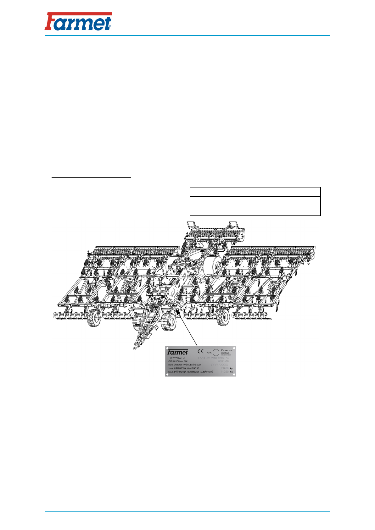
The serial number of the machine is punched on the production label and written in the operating
manual (Your Machine Characteristics). This machine serial number must be stated whenever ordering spare
parts for possible repairs. The production label is located on the frame .
Use only spare parts for these machines according to the Spare parts catalogue officially issued by
the manufacturer, Farmet a.s. Česka Skalice.
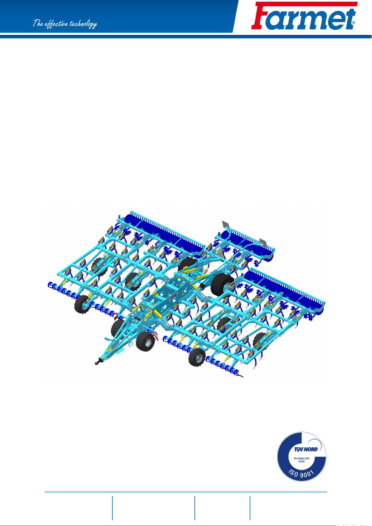
Possibilities of Use of the Cultivator
The FANTOM PRO cultivator is designed for cultivation of all types of soils up to a processing depth of
15 cm.
Your Machine Characteristics :
MACHINE TYPE :
MACHINE SERIAL NUMBER :
SPECIAL DESIGN OR ACCESSORIES :


PREFACE
5 | 59
Contents
PREFACE . . . . . . . . . . . . . . . . . . . . . . . . . . . . . . . . . . . . . . . . . . . . . . . . . . . . . . . . . . . . . . . . . . . . . . . . . . . . . . . . . . . . . . . . . . . . . . . . . . . . . . . . . . . . . . . . . . . . . . . . . . . . . . . . . 3
1 MACHINE LIMIT PARAMETERS . . . . . . . . . . . . . . . . . . . . . . . . . . . . . . . . . . . . . . . . . . . . . . . . . . . . . . . . . . . . . . . . . . . . . . . . . . . . . . . . . . . . . . . 7
1.1 Technical parameters. . . . . . . . . . . . . . . . . . . . . . . . . . . . . . . . . . . . . . . . . . . . . . . . . . . . . . . . . . . . . . . . . . . . . . . . . . . . . . . . . . . . . . . . . . 7
1.2 Machine weight distribution during transport . . . . . . . . . . . . . . . . . . . . . . . . . . . . . . . . . . . . . . . . . . . . . . . . . . 8
1.3 Safety statement. . . . . . . . . . . . . . . . . . . . . . . . . . . . . . . . . . . . . . . . . . . . . . . . . . . . . . . . . . . . . . . . . . . . . . . . . . . . . . . . . . . . . . . . . . . . . . . . . . 8
2 GENERAL INSTRUCTIONS FOR USE . . . . . . . . . . . . . . . . . . . . . . . . . . . . . . . . . . . . . . . . . . . . . . . . . . . . . . . . . . . . . . . . . . . . . . . . . . . . 9
3 MACHINE TRANSPORT USING TRANSPORT MEANS . . . . . . . . . . . . . . . . . . . . . . . . . . . . . . . . . . . . . . . . . . . . 11
4 MACHINE HANDLING USING LIFTING EQUIPMENT . . . . . . . . . . . . . . . . . . . . . . . . . . . . . . . . . . . . . . . . . . . . . . . . 12
5 WORK SAFETY LABELS. . . . . . . . . . . . . . . . . . . . . . . . . . . . . . . . . . . . . . . . . . . . . . . . . . . . . . . . . . . . . . . . . . . . . . . . . . . . . . . . . . . . . . . . . . . . . . . . . . 13
6 DESCRIPTION. . . . . . . . . . . . . . . . . . . . . . . . . . . . . . . . . . . . . . . . . . . . . . . . . . . . . . . . . . . . . . . . . . . . . . . . . . . . . . . . . . . . . . . . . . . . . . . . . . . . . . . . . . . . . . . . . . . . 17
6.1 Working parts of the machine . . . . . . . . . . . . . . . . . . . . . . . . . . . . . . . . . . . . . . . . . . . . . . . . . . . . . . . . . . . . . . . . . . . . . . . . . . 17
6.2 Function of the closing (ball) valves . . . . . . . . . . . . . . . . . . . . . . . . . . . . . . . . . . . . . . . . . . . . . . . . . . . . . . . . . . . . . . . 18
7 MACHINE ASSEMBLY AT THE CUSTOMER. . . . . . . . . . . . . . . . . . . . . . . . . . . . . . . . . . . . . . . . . . . . . . . . . . . . . . . . . . . . . . . . 20
8 COMMISSIONING. . . . . . . . . . . . . . . . . . . . . . . . . . . . . . . . . . . . . . . . . . . . . . . . . . . . . . . . . . . . . . . . . . . . . . . . . . . . . . . . . . . . . . . . . . . . . . . . . . . . . . . . . . . . . . 21
8.1 Agregation to a tractor . . . . . . . . . . . . . . . . . . . . . . . . . . . . . . . . . . . . . . . . . . . . . . . . . . . . . . . . . . . . . . . . . . . . . . . . . . . . . . . . . . . . . . 22
8.2 Hydraulics. . . . . . . . . . . . . . . . . . . . . . . . . . . . . . . . . . . . . . . . . . . . . . . . . . . . . . . . . . . . . . . . . . . . . . . . . . . . . . . . . . . . . . . . . . . . . . . . . . . . . . . . . . . 23
8.2.1 Hydraulic scheme FANTOM 1050 PRO, 1250 PRO. . . . . . . . . . . . . . . . . . . . . . . . . . . 25
8.2.2 Pressure vessel. . . . . . . . . . . . . . . . . . . . . . . . . . . . . . . . . . . . . . . . . . . . . . . . . . . . . . . . . . . . . . . . . . . . . . . . . . . . . . . . . . . . . . . . 29
8.3 Folding and unfolding of the machine. . . . . . . . . . . . . . . . . . . . . . . . . . . . . . . . . . . . . . . . . . . . . . . . . . . . . . . . . . . . . 29
8.3.1 Machine unfolding procedure. . . . . . . . . . . . . . . . . . . . . . . . . . . . . . . . . . . . . . . . . . . . . . . . . . . . . . . . . . . . . . . . . 31
8.3.2 Machine Folding Procedure. . . . . . . . . . . . . . . . . . . . . . . . . . . . . . . . . . . . . . . . . . . . . . . . . . . . . . . . . . . . . . . . . . . . 32
8.3.3 Securing the frames against unfolding during transport . . . . . . . . . . . . . . . . . . . . 33
8.3.4 Aggregation to the tractor using the three-point hitch –
Transport . . . . . . . . . . . . . . . . . . . . . . . . . . . . . . . . . . . . . . . . . . . . . . . . . . . . . . . . . . . . . . . . . . . . . . . . . . . . . . . . . . . . . . . . . . . . . . . . 34
8.4 Brake distribution of the machine . . . . . . . . . . . . . . . . . . . . . . . . . . . . . . . . . . . . . . . . . . . . . . . . . . . . . . . . . . . . . . . . . . . 35
8.4.1 Hand brake control valve . . . . . . . . . . . . . . . . . . . . . . . . . . . . . . . . . . . . . . . . . . . . . . . . . . . . . . . . . . . . . . . . . . . . . . . 36
8.4.2 Emergency brake release in case of air leak . . . . . . . . . . . . . . . . . . . . . . . . . . . . . . . . . . . . . . 37
8.5 Description of the share/chisel replacement . . . . . . . . . . . . . . . . . . . . . . . . . . . . . . . . . . . . . . . . . . . . . . . . 38
9 REAR ACCESSORIES. . . . . . . . . . . . . . . . . . . . . . . . . . . . . . . . . . . . . . . . . . . . . . . . . . . . . . . . . . . . . . . . . . . . . . . . . . . . . . . . . . . . . . . . . . . . . . . . . . . . . . 39
9.1 Quick-change roller system . . . . . . . . . . . . . . . . . . . . . . . . . . . . . . . . . . . . . . . . . . . . . . . . . . . . . . . . . . . . . . . . . . . . . . . . . . . . 41
9.2 Setting the parallelogram . . . . . . . . . . . . . . . . . . . . . . . . . . . . . . . . . . . . . . . . . . . . . . . . . . . . . . . . . . . . . . . . . . . . . . . . . . . . . . . . 42
9.3 Setting the levelling disc . . . . . . . . . . . . . . . . . . . . . . . . . . . . . . . . . . . . . . . . . . . . . . . . . . . . . . . . . . . . . . . . . . . . . . . . . . . . . . . . . . 43
9.4 Setting g levelling . . . . . . . . . . . . . . . . . . . . . . . . . . . . . . . . . . . . . . . . . . . . . . . . . . . . . . . . . . . . . . . . . . . . . . . . . . . . . . . . . . . . . . . . . . . . . 44
9.4.1 Levelling pressure. . . . . . . . . . . . . . . . . . . . . . . . . . . . . . . . . . . . . . . . . . . . . . . . . . . . . . . . . . . . . . . . . . . . . . . . . . . . . . . . . . . . 44
9.4.2 Setting the rear flexiboard . . . . . . . . . . . . . . . . . . . . . . . . . . . . . . . . . . . . . . . . . . . . . . . . . . . . . . . . . . . . . . . . . . . . . . 45
9.4.3 Setting the angle of rear levelling . . . . . . . . . . . . . . . . . . . . . . . . . . . . . . . . . . . . . . . . . . . . . . . . . . . . . . . . . . 46
10 MACHINE TRANSPORT ON ROADS . . . . . . . . . . . . . . . . . . . . . . . . . . . . . . . . . . . . . . . . . . . . . . . . . . . . . . . . . . . . . . . . . . . . . . . . . . 47
11 MACHINE ADJUSTMENT. . . . . . . . . . . . . . . . . . . . . . . . . . . . . . . . . . . . . . . . . . . . . . . . . . . . . . . . . . . . . . . . . . . . . . . . . . . . . . . . . . . . . . . . . . . . . . . 48
11.1 Adjusting the working depth of the machine . . . . . . . . . . . . . . . . . . . . . . . . . . . . . . . . . . . . . . . . . . . . . . . 49
11.2 Adjusting the height of tines behind the transport axle . . . . . . . . . . . . . . . . . . . . . . . . . . . . . 50
11.3 Adjusting the roller pressure . . . . . . . . . . . . . . . . . . . . . . . . . . . . . . . . . . . . . . . . . . . . . . . . . . . . . . . . . . . . . . . . . . . . . . . . . 51
11.4 Adjusting the efficiency of the flexiboard . . . . . . . . . . . . . . . . . . . . . . . . . . . . . . . . . . . . . . . . . . . . . . . . . . . . . 52
12 MACHINE MAINTENANCE AND REPAIRS . . . . . . . . . . . . . . . . . . . . . . . . . . . . . . . . . . . . . . . . . . . . . . . . . . . . . . . . . . . . . . . . 53
13 MACHINE STORAGE. . . . . . . . . . . . . . . . . . . . . . . . . . . . . . . . . . . . . . . . . . . . . . . . . . . . . . . . . . . . . . . . . . . . . . . . . . . . . . . . . . . . . . . . . . . . . . . . . . . . . . 54
14 MACHINE LUBRICATION SCHEDULE. . . . . . . . . . . . . . . . . . . . . . . . . . . . . . . . . . . . . . . . . . . . . . . . . . . . . . . . . . . . . . . . . . . . . . . . 55

PREFACE
6 | 59
15 ENVIROMENTAL PROTECTION . . . . . . . . . . . . . . . . . . . . . . . . . . . . . . . . . . . . . . . . . . . . . . . . . . . . . . . . . . . . . . . . . . . . . . . . . . . . . . . . . . 56
16 MACHINE DISPOSAL AFTER SERVICE LIFE EXPIRY. . . . . . . . . . . . . . . . . . . . . . . . . . . . . . . . . . . . . . . . . . . . 57
17 SERVICING AND WARRANTY CONDITIONS . . . . . . . . . . . . . . . . . . . . . . . . . . . . . . . . . . . . . . . . . . . . . . . . . . . . . . . . . . . 58
17.1 Servicing. . . . . . . . . . . . . . . . . . . . . . . . . . . . . . . . . . . . . . . . . . . . . . . . . . . . . . . . . . . . . . . . . . . . . . . . . . . . . . . . . . . . . . . . . . . . . . . . . . . . . . . . . . . 58
17.2 Warranty . . . . . . . . . . . . . . . . . . . . . . . . . . . . . . . . . . . . . . . . . . . . . . . . . . . . . . . . . . . . . . . . . . . . . . . . . . . . . . . . . . . . . . . . . . . . . . . . . . . . . . . . . . . 58

7 | 59
MACHINE LIMIT PARAMETERS
1 MACHINE LIMIT PARAMETERS
• The machine is designed for soil ploughing up to a depth of 15 cm when agricultural soil cultivation.
Another type of use exceeding the determined purpose is forbidden.
• The machine is only operated by one person – the tractor operator.
• Machine operator must not use the machine in a different way, especially:
Transport of persons and animals on the machine structure,
Transport of burdens on the machine structure,
Aggregation of the machine with another towing equipment than stated in Chapter „8.1“.
1.1 Technical parameters
PARAMETERS FANTOM 1050 PRO FANTOM 1250 PRO
Working width 10,5 m 12,5 m
Transport width 3 m***
Transport height 3,7 m 3,998 m
Machine total length 9,64 m
Working depth 4 – 15 cm
Number of shares 57 67
Working performance 8,4 – 12,6 ha/h 10 – 15 ha/h
Towing means 295 – 400 kW* 400 – 440 kW*
Working speed 8 – 12 km/h
Maximum transport speed 20 km/h
Maximum slope grade (°) 6
Tyre dimensions - transport
Tyre pressure 504/70-20
480 kPa
Machine weight 11 160 kg** 14 480 kg**
* Recommended towing means, the real towing force may significantly vary according to the processing
depth, soil conditions, land slope, working body wear and adjustment.
** Weight of the machine with SD rollers and front flexi-board
*** Only applies to the version with standard tines length; the width of the machine is higher when the
extended version of tines is used!!!
MACHINE LIMIT PARAMETERS
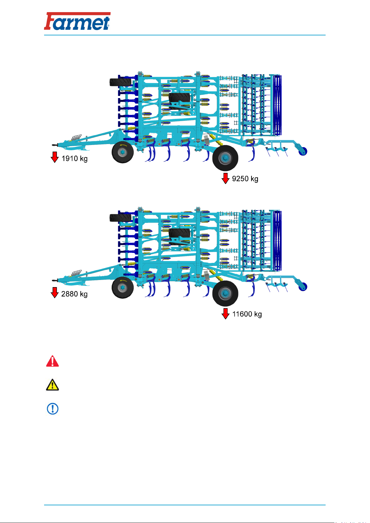
1.2 Machine weight distribution during transport
FANTOM 1050 PRO
FANTOM 1250 PRO
1.3 Safety statement
This warning sign warns about an immediate dangerous situation ending with death or
severe injury.
This warning sign warns about a dangerous situation ending with death or severe injury.
This warning sign warns about a situation that may end with a smaller or slight injury. It
also warns about dangerous actions related to the activity that could lead to an injury.
8 | 59

9 | 59
GENERAL INSTRUCTIONS FOR USE
2 GENERAL INSTRUCTIONS FOR USE
• The machine is made in accordance with the latest equipment state and approved safety
regulations. However, dangers of user or third person injury or machine damage or
creation of other material damage may arise during use.
• Use the machine only in a technically sound condition, in accordance with its purpose,
aware of possible dangers, and while adhering to the safety instructions of this operating
manual! The manufacturer is not liable for damages caused by the use of the machine
that is in contradiction with the limit parameters of the machine and with the
instructions for the use of the machine . The user bears the risk.
Immediately remove especially the failures that may negatively affect safety!
• Machine operation may be performed by a person authorised by the operator under
these conditions :
• It must own a valid driver's licence of the corresponding category,
• It must be demonstrably familiarised with the safety regulations for work with the
machine and must practically master the machine operation,
• The machine may not be operated by juveniles,
• It must know the meaning of the safety signs located on the machine. Their
respecting is important for safe and reliable machine operation.
• Maintenance and servicing repairs on the machine may only be performed by a person :
• Authorised by the operator,
• Educated in the machinery field with knowledge of repairs of similar machines,
• Demonstrably familiarised with safety regulations for work with the machine,
• During a repair of a machine connected to a tractor, it must own a driver's licence of
the corresponding category.
• Machine operator must secure the safety of other persons when working with the
machine or transporting the machine.
• During machine work in the field or during transport, the operator must control the
machine from the tractor's cabin.
• The operator may enter the machine structure only with the machine at rest and blocked
against movement, namely only for these reasons :
• Adjustment of the machine working parts,
• Repair and maintenance of the machine,
• Adjustment of the working parts of the machine after unfolding the side frames.
• When stepping on the machine, do not step on roller tyres or other rotary parts. Those
may turn and you can cause very serious injuries by the subsequent fall.
• Any changes or modifications of machine may be performed only with written consent of
the manufacturer.
For possible damage arisen due to ignoring this instruction, the producer bears no
responsibility.
The machine must be maintained equipped with prescribed accessories and equipment
including safety marking.
All warning and safety signs must be legible and in their places. In case of damage or loss,
these signs must be immediately renewed.
• The operator must have the Operating Manual with the work safety requirements
available at any time when working with the machine.

GENERAL INSTRUCTIONS FOR USE
• The operator must not consume alcohol, medicines, narcotic and hallucinogenic
substances that decrease his attention and coordination capabilities while using the
machine.
If the operator must use medicines prescribed by a physician or uses freely sold
medicines, he must be informed by a physician, whether he is capable of responsible and
safe operation of the machine under these circumstances.
Protective equipment
For operation and maintenance use:
• tight clothes
• protective gloves and goggles against dust and
sharp parts of the machine.
10 | 59

11 | 59
MACHINE TRANSPORT USING TRANSPORT MEANS
3 MACHINE TRANSPORT USING TRANSPORT MEANS
• The transport means designed for machine transport must have the load capacity minimally
identical with the weight of the transported machine. The total weight of the machine is stated
on the production label.
• The dimensions of the transported machine including the transport means must comply with
the valid regulations for road traffic (decrees, laws).
• The transported machine must be always fastened to the transport means so that its
spontaneous loosening could not happen.
• The carrier is responsible for damage caused by the loosening of incorrectly or insufficiently
fastened machine to the transport means.

12 | 59
MACHINE HANDLING USING LIFTING EQUIPMENT
4 MACHINE HANDLING USING LIFTING EQUIPMENT
• The lifting equipment and tying means designed for handling of the machine must have their
load capacity at least identical with the weight of the handled machine.
• Machine fastening for handling may only be performed in places designed for that and
marked with self-adhesive labels showing the "chain" symbol.
• After fastening (suspending) at designated points, it is forbidden to move in the space of
possible reach of the handled machine.
13 | 59
WORK SAFETY LABELS
5 WORK SAFETY LABELS
Warning safety labels serve for operator protection.
General:
• Strictly observe the warning safety labels.
• All safety instructions also apply to other users.
• Upon damage or destruction of the aforementioned "SAFETY LABEL" located on the machine, THE
OPERATOR IS OBLIGED TO REPLACE IT WITH A NEW ONE!!!
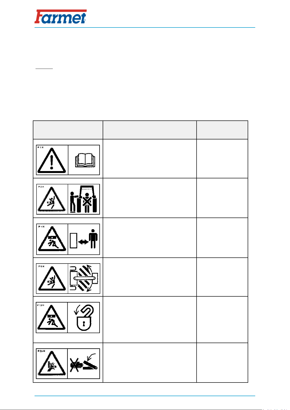
• The position, appearance and the precise meaning of the work safety labels on the machine are
defined in the following tables and the figure .
WARNING SAFETY LABEL LABEL TEXT MACHINE
POSITION
Before handling the machine, carefully read
the operating manual.
Observe the instructions and safety
regulations for machine operation during
use.
P 1 H
When connecting or disconnecting, do not
step between the tractor and the machine,
also do not enter this space, if the tractor
and the machine are not at rest and the
engine is not turned off.
P 2 H
Stay out of reach of the drawn-up machine. P 4 H
Stay outside the reach of the tractor -
agricultural machine set, if the tractor
engine is in operation. P 6 H
The side extensible disc must be secured
with the stopper for transport and during
work.
The rear twin roller must be secured with
the stopper for transport.
Before commencing the machine transport,
secure the axle with spherical valves against
unexpected drop.
P 13 H
When folding the side frames, do not reach
into the space of the machine folding joints.
There is a danger of cutting when setting
the depth of the machine. P 20 H

WORK SAFETY LABELS
Travelling and transport on the machine
structure is strictly forbidden. P 37 H
When working and transporting the
machine, maintain safe distance from the
electric appliances P 39 H
The pressure vessel is under gas and oil
pressure. Execute disassembly and repairs
only according to the instructions in the
manual. P 42 H
When folding and unfolding the side frames,
stay outside their reach. P 50 H
Secure the machine against unwanted
movement by positioning on its working
bodies (shares). P 52 H
Stay outside the reach of the tractor -
agricultural machine set, if the tractor
engine is in operation. P 53 H
It is strictly folding and unfolding the side
frames on slopes or inclined surfaces. P 100 H
The shown positions of the lever and the
function of the hydraulic spherical valve
located on the piston rod. P 101 H
14 | 59


17 | 59
DESCRIPTION
6 DESCRIPTION
FANTOM 1050 PRO, FANTOM 1250 PRO is structurally designed as a semi-mounted folding machine.
The basic version consists of a drawbar and a working section. The chassis is aggregated with the pulling ve-
hicle using a height-adjustable loop for guide pin ø50mm (ø70mm or K80 hitch). The chassis includes a sup-
porting leg to support the machine after it is disconnected from the tractor.
The working section consists of a central frame with the transport axle, of the two side frames and of
the two outer frames. There are five rows of working shares and tracing wheels on the central and side
frames. Furthermore, there are rollers in the rear part of the machine that compact the aerated soil. The
machine is designed for work with or without rollers. The roller hitches are equipped with a quick-coupling
system for fast disassembly. It is possible to install a front flexi-board in front of the first row of ploughshares
on request to increase the levelling effect during work. The axle is located inside the machine in front of the
rear roller. The tracing wheels are used for setting the working depth.
The machine must not be operated with lifted rear rollers for a long time, the rollers can be
quickly removed using the quick-coupling system, see Chapter 9.1 !!!
6.1 Working parts of the machine
1. Tractive pole with a folding leg
2. Tracing wheel
3. Flexi-board / Coulters
4. Five rows of shares
5. Rear levelling discs
6. Roller
7. Transportation axle

DESCRIPTION
6.2 Function of the closing (ball) valves
• The machine is equipped with two closing (ball) valves and two switching (three-way) valves
inside the drawbar, see Fig. 2 and 3.
• The external upper ball valve is used for closing the circuit for side frame unfolding (red
circuit); its use is further described in Chapter 8.3.
• The external lower ball valve is used for closing the circuit controlling the piston-rods of the
transport axle (yellow circuit), its use is further described in Chapter 8.3.
• The two ball switching (three-way) valves in the front part of the drawbar are used for
switching the function of the blue circuit. During operation, the blue circuit controls the flexi-
board (if installed) and the folding supporting leg of the drawbar.
• It is important to close the ball valves for transport !!!
Fig. 2 - closing (ball) valves
1. Unfolding machine frames
2. Locking/unlocking transport axle
3. Switching (three-way) valves
Fig. 3 - Switching (three-way) valves
The switching valves in this position control the
flexi-board.
The switching valves in this position control the
supporting leg of the drawbar.
18 | 59


20 | 59
MACHINE ASSEMBLY AT THE CUSTOMER
7 MACHINE ASSEMBLY AT THE CUSTOMER
• The operator must perform the assembly according to the instructions of the producer,
best in cooperation with the expert servicing technician determined by the producer.
• The operator must secure a functional test of all assembled parts after the completion
of the machine assembly.
• The operator must secure that the handling of the machine using lifting equipment during
its assembly is in accordance with chapter „4“.
This manual suits for next models
1
Table of contents
Other Farmet Tiller manuals


