Farmet FANTOM FX 850 PS User manual
web: www.farmet.cz
e-mail: farmet@farmet.cz
IČ: 46504931
DIČ: CZ46504931
Farmet a. s.
Jiřinková 276
552 03 Česká Skalice, CZ
telefon: +420 491 450 111
fax: +420 491 450 136
GSM: +420 774 715 738
OPERATING MANUAL
FANTOM
FX 850 PS
Edition: 1 | effective from: 1. 7. 2020

Manual
FANTOM 850 PS
2 │33
Dear customer,
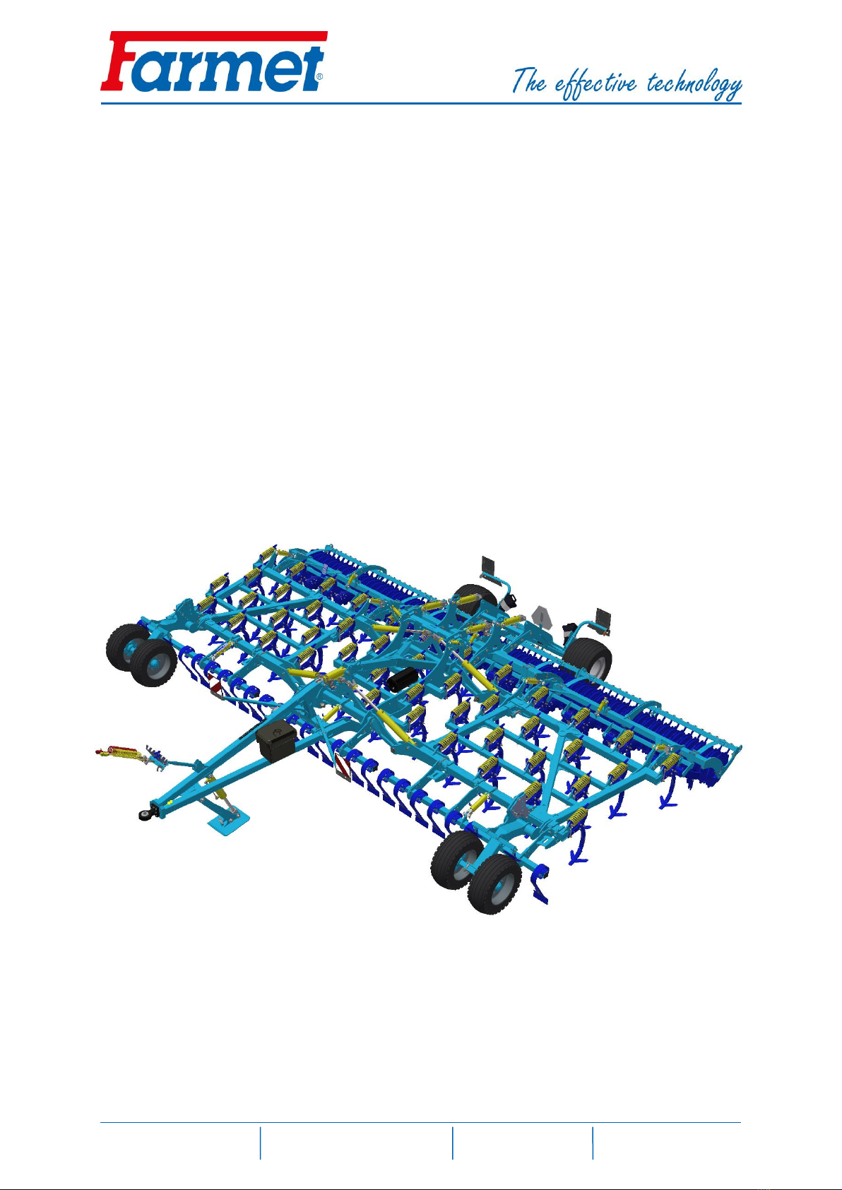
Semi-carried cultivators FANTOM are quality products of Farmet a.s. Ceska Skalice.
You can fully utilise the advantages of your machine after thoroughly studying the operating manual.
The serial number of the machine is punched on the production label and written in the operating manual
(see Table 1). This machine serial number must be stated whenever ordering spare parts for possible repairs. The
production label is located on the middle frame near the tow bar.
Use only spare parts for these machines according to the Spare parts catalogue officially issued by the
manufacturer, Farmet a.s. Ceska Skalice.
Possibilities of Use of the Cultivator
The FANTOM cultivator is designed for cultivation of all types of soils up to a processing depth of
150mm.
Production label of the machine FANTOM FX 850 PS
Table 1 –Your Machine Characteristics
MACHINE TYPE
MACHINE SERIAL NUMBER
SPECIAL DESIGN OR ACCESSORIES
....................................................................................................................................................................
....................................................................................................................................................................
....................................................................................................................................................................
...............................................................……………………………….
9 000
6 000
FANTOM / FX 850 PS

Manual
FANTOM 850 PS
3 │33
TABLE OF CONTENTS
MACHINE LIMIT PARAMETERS................................................................................................................ 4
Technical parameters......................................................................................................................... 4
Machine weight distribution during transport .................................................................................. 5
Safety statement................................................................................................................................ 5
A. GENERAL INSTRUCTIONS FOR USE..................................................................................................... 6
PROTECTIVE EQUIPMENT................................................................................................................... 6
B. MACHINE TRANSPORT USING TRANSPORT MEANS .......................................................................... 7
C. MACHINE HANDLING USING LIFTING EQUIPMENT ........................................................................... 8
D. WORK SAFETY LABELS........................................................................................................................ 9
1. DESCRIPTION.................................................................................................................................... 12
1.1. Work parts of the machine....................................................................................................... 12
1.2. Hydraulics ................................................................................................................................. 12
2. MACHINE ASSEMBLY AT THE CUSTOMER........................................................................................ 14
3. COMMISSIONING ............................................................................................................................. 14
3.1. Aggregation to a tractor ........................................................................................................... 15
3.2. Hydraulics connection .............................................................................................................. 16
3.3. Hydraulics control panel........................................................................................................... 18
3.4. Folding and unfolding of the machine...................................................................................... 22
3.4.1. Machine unfolding procedure............................................................................... 23
3.4.2. Machine folding procedure................................................................................... 24
4. MACHINE TRANSPORT ON ROADS................................................................................................... 25
5. MACHINE ADJUSTMENT................................................................................................................... 26
5.1. Machine working depth adjustment........................................................................................ 26
5.1.1. Ajustment of depth on rollers ............................................................................... 27
5.1.2. Hitch height related settings ................................................................................. 27
5.1.3. Depth adjustment on the copying wheels ............................................................ 27
5.2. Front tools depth setting.......................................................................................................... 28
5.3. Levelling disc adjustment ......................................................................................................... 29
6. MACHINE MAINTENANCE AND REPAIRS.......................................................................................... 30
7. MACHINE STORAGE.......................................................................................................................... 31
8. MACHINE LUBRICATION SCHEDULE................................................................................................. 31
9. ENVIRONMENTAL PROTECTION....................................................................................................... 32
10.MACHINE DISPOSAL AFTER SERVICE LIFE EXPIRY ............................................................................ 32
11.SERVICING AND WARRANTY CONDITIONS....................................................................................... 32
CE Certificate of Conformity ....................................................................................................... 33
G
B

Manual
FANTOM 850 PS
4 │33
MACHINE LIMIT PARAMETERS
(x) The machine is designed for soil cultivation up to a depth of 15 cm when agricultural soil cultivation.
Another type of use exceeding the determined purpose is forbidden.
(x) The machine is only operated by one person - the tractor operator.
(x) Machine operator must not use the machine in a different way, especially:
(x) Transport of persons and animals on the machine structure,
(x) Transport of burdens on the machine structure,
(x) Aggregation of the machine with another towing equipment than stated in Chapter „3.1“.
TECHNICAL PARAMETERS
Table 2 –Technical Parameter
PARAMETERS
FANTOM FX 850 PS
Working width (mm)
8,550
Transport width (mm)
3,000
Transport height (mm)
4,000
Machine total length (mm)
8,700
Distance from the towing lug to the roller (mm)
6,900
Working depth (mm)
5 –150
Number of shares
45
Working performance (ha/h)
6.8 –10.2
Towing means (kW)
245 –370*
Working speed (kph)
8 –12
Maximum transport speed (kph)
30
Working depth (mm)
6
Tyre dimensions - transport
Tyre pressure (kPa)
19.0/45-17 14PR
400 kPa
Machine weight (kg)
* Recommended towing means, the real towing force may significantly vary according to the processing depth,
soil conditions, land slope, working body wear and adjustment.
** Weight with the LTX roller and front crossboards

Manual
FANTOM 850 PS
5 │33
MACHINE WEIGHT DISTRIBUTION DURING TRANSPORT
SAFETY STATEMENT
This warning sign warns about an immediate dangerous situation ending
with death or severe injury.
This warning sign warns about a dangerous situation ending with death or
severe injury.
This warning sign warns about a situation that may end with a smaller or
slight injury. It also warns about dangerous actions related to the activity
that could lead to an injury.
3 000 kg
6 000 kg

Manual
FANTOM 850 PS
6 │33
A. GENERAL INSTRUCTIONS FOR USE
A.1 (x) The machine is made in accordance with the latest equipment state and approved safety regulations.
However, dangers of user or third person injury or machine damage or creation of other material damage
may arise during use.
A.2 (xx) Use the machine only in a technically sound condition, in accordance with its purpose, aware of possible
dangers, and while adhering to the safety instructions of this operating manual!
The manufacturer is not liable for damages caused by the use of the machine that is in contradiction with
the limit parameters of the machine and with the instructions for the use of the machine. The user bears
the risk.
Immediately remove especially the failures that may negatively affect safety!
A.3 (7) Machine operation may be performed by a person authorised by the operator under these conditions:
(8) It must own a valid driver's licence of the corresponding category,
(9) It must be demonstrably familiarised with the safety regulations for work with the machine and
must practically master the machine operation,
(10) The machine may not be operated by juveniles,
(11) It must know the meaning of the safety signs located on the machine. Their respecting is important
for safe and reliable machine operation.
A.4 (12) Maintenance and servicing repairs on the machine may only be performed by a person:
(13) Authorised by the operator,
(14) Educated in the machinery field with knowledge of repairs of similar machines,
(15) Demonstrably familiarised with safety regulations for work with the machine,
(16) During a repair of a machine connected to a tractor, it must own a driver's licence of the
corresponding category.
A.5 (17) Machine operator must secure the safety of other persons when working with the machine or
transporting the machine.
A.6 (18) During machine work in the field or during transport, the operator must control the machine from the
tractor's cabin.
A.7 (19) The operator may enter the machine structure only with the machine at rest and blocked against
movement, namely only for these reasons:
(20) Adjustment of the machine working parts,
(21) Repair and maintenance of the machine,
(28) Adjustment of the working parts of the machine after unfolding the side frames.
A.8 When climbing on the machine, do not step on the axle tyres, rollers or other revolving parts. Those may
turn and you can cause very serious injuries by the subsequent fall.
A.9 (22) Any changes or modifications of machine may be performed only with written consent of the
manufacturer. For possible damage arisen due to ignoring this instruction, the producer bears no
responsibility. The machine must be maintained equipped with prescribed accessories and equipment
including safety marking. All warning and safety signs must be legible and in their places. In case of damage
or loss, these signs must be immediately renewed.
A.10 (23) The operator must have the Operating Manual with the work safety requirements available at any time
when working with the machine.
A.11 (24) The operator must not consume alcohol, medicines, narcotic and hallucinogenic substances that
decrease his attention and coordination capabilities while using the machine. If the operator must use
medicines prescribed by a physician or uses freely sold medicines, he must be informed by a physician,
whether he is capable of responsible and safe operation of the machine under these circumstances.
PROTECTIVE EQUIPMENT
For operation and maintenance use:
Tight clothe
Protective gloves and goggles for protection against dust and sharp parts
of the machine
Manual
FANTOM 850 PS
7 │33
B. MACHINE TRANSPORT USING TRANSPORT MEANS
B.1 (1) The transport means designed for machine transport must have the load capacity minimally identical
with the weight of the transported machine. The total weight of the machine is stated on the production
label.
B.2 (2) The dimensions of the transported machine including the transport means must comply with the valid
regulations for road traffic (decrees, laws).
B.3 (3) The transported machine must be always fastened to the transport means so that its spontaneous
loosening could not happen.
B.4 (4) The carrier is responsible for damage caused by the loosening of incorrectly or insufficiently fastened
machine to the transport means.
Manual
FANTOM 850 PS
8 │33
C. MACHINE HANDLING USING LIFTING EQUIPMENT
C.1 (1) The lifting equipment and tying means designed for handling of the machine must have their load
capacity at least identical with the weight of the handled machine.
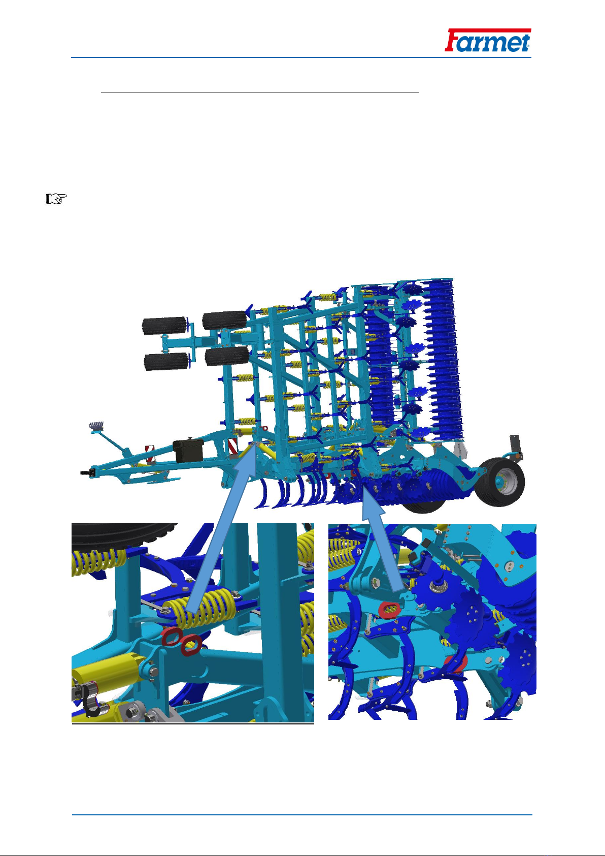
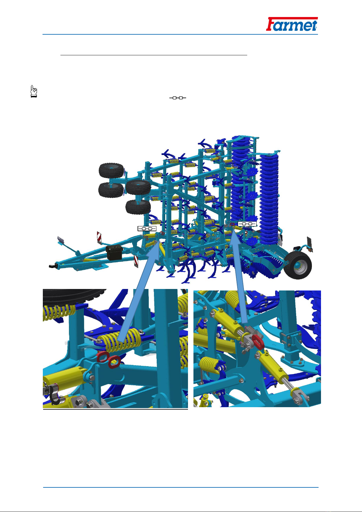
C.2 (2) Machine fastening for handling may only be performed in places designed for that and marked with self-
adhesive labels showing the "chain" symbol.
C.3 (3) After fastening (suspending) at designated points, it is forbidden to move in the space of possible reach
of the handled machine.

Manual
FANTOM 850 PS
9 │33
D. WORK SAFETY LABELS
Warning safety labels serve for operator protection.
General:
A) Strictly observe the warning safety labels.
B) All safety instructions also apply to other users.
C) Upon damage or destruction of the aforementioned "SAFETY LABEL" located on the machine, THE OPERATOR
IS OBLIGED TO REPLACE IT WITH A NEW ONE!!!
The position, appearance, and precise meaning of work safety labels on the machine is determined in
the following tables (Tab. 3) and in the figure (Fig. 1).
Table 3 –Self-adhesive warning safety labels located on the cultivator
WARNING SAFETY LABEL
LABEL TEXT
MACHINE POSITION
Before handling the machine,
carefully read the operating manual.
Observe the instructions and safety
regulations for machine operation
during use.
P 1 H
Travelling and transport on the
machine structure is strictly
forbidden.
P 37 H
When connecting or disconnecting,
do not step between the tractor and
the machine, also do not enter this
space, if the tractor and the machine
are not at rest and the engine is not
turned off.
P 2 H
When folding and unfolding the side
frames, stay outside their reach.
P 50 H
Stay outside the reach of the tractor
- agricultural machine set, if the
tractor engine is in operation.
P 6 H
When folding the side frames, do not
reach into the space of the machine
folding joints.
There is a danger of cutting when
setting the depth of the machine.
P 20 H
Before commencing the machine
transport, secure the axle with
spherical valves against unexpected
drop.
P 13 H
When working and transporting the
machine, maintain safe distance
from the electric appliances.
P 39 H
Manual
FANTOM 850 PS
10 │33
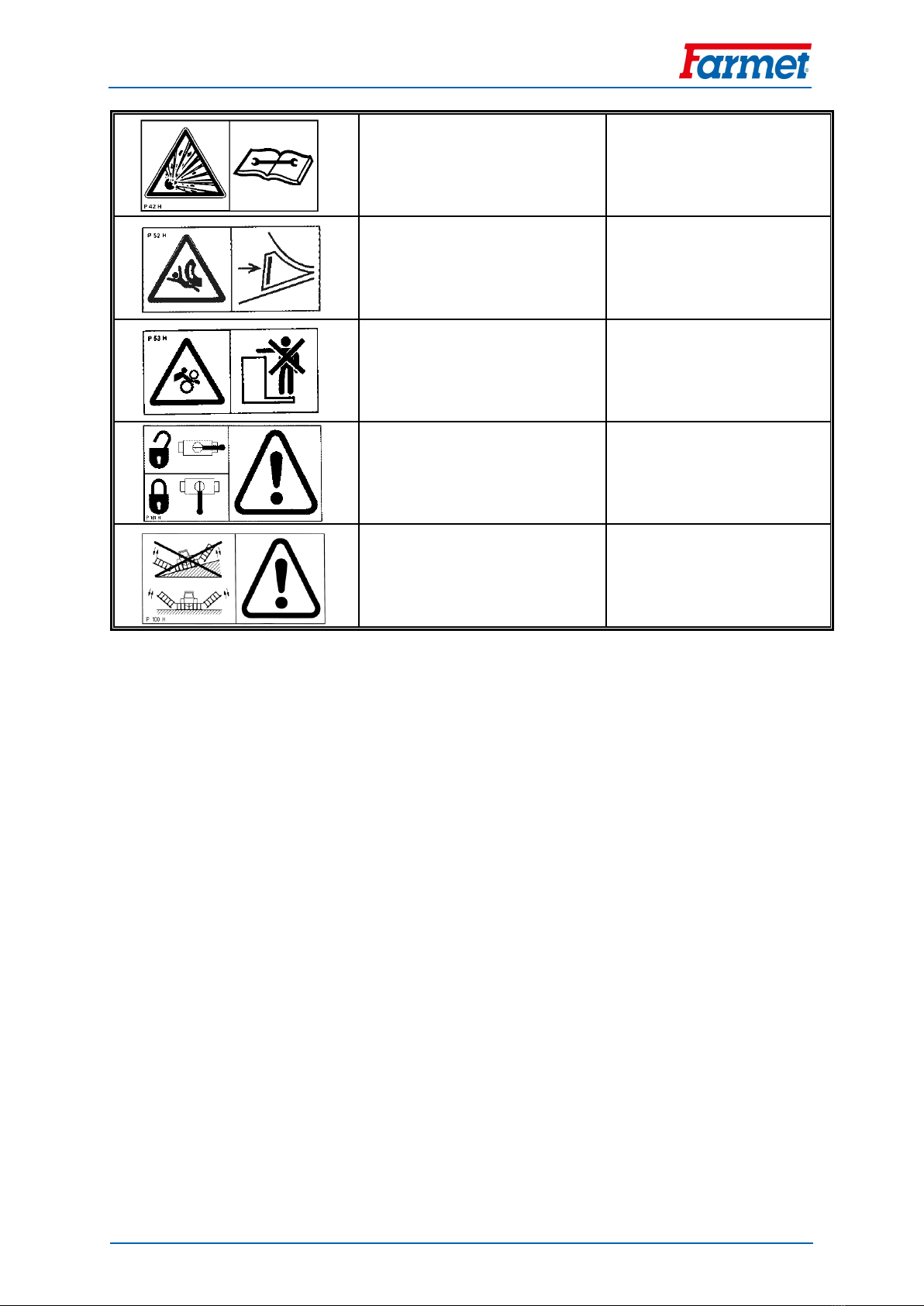
The pressure vessel is under gas and
oil pressure. Execute disassembly
and repairs only according to the
instructions in the manual.
P 42 H
Secure the machine against
unwanted movement by positioning
on its working bodies.
P 52 H
Stay outside the reach of the tractor
- agricultural machine set, if the
tractor engine is in operation.
P 53 H
The shown positions of the lever and
the function of the hydraulic
spherical valve located on the piston
rod.
P 101 H
Before commencing the machine
transport, secure the axle with
spherical valves against unexpected
drop.
P 100 H

Manual
FANTOM 850 PS
11 │33
Fig. 1 –Location of safety labels on the machine
P1H
P2H
P6H
P100H
P52H
P37H
P53H
P37H
P53H
P20H
P37H
P53H
P50H
P52H
P20H
P20H
P13H
P101H
P39H
P53H
P20H
P50H
P42H
P20H
P37H
P53H
P20H
P50H
P39H
P53H

Manual
FANTOM 850 PS
12 │33
1.1.5
Central frame
Boční rámy
1.1.1
1.1.4
1.1.3
1.1.7
Side frame
1.1.2
1.1.6
1. DESCRIPTION
The FANTOM FX 850 PS machine is constructed as semi-carried. The basic version consists of a tractive pole
with a TPS suspension bar with 36 mm or 60 mm pivots for the TPS 3 and KIROVEC category, or a loop for
bottom hitch (51 mm, 71 mm or K80 hitch), a central frame with the transportation axle and four side frames.
There are four rows of working shares located on the central and side frames and tracing wheels on the side
frames. Furthermore, there are rollers in the rear of the machine that compact the loosened soil. In front of the
first row, it is possible to mount front tools upon request, i.e. a crossboard, a cutting roller, or coulters. Behind
the rear roller in the middle part, the machine axle is located.
1.1. WORK PARTS OF THE MACHINE
Fig. 2 –Work Parts of the Machine
1.1.1 Tractive pole with a folding leg
1.1.2 Supporting wheel
1.1.3 Front tools
1.1.4 Four rows of shares
1.1.5 Rear levelling discs
1.1.6 Roller
1.1.7 Transportation axle
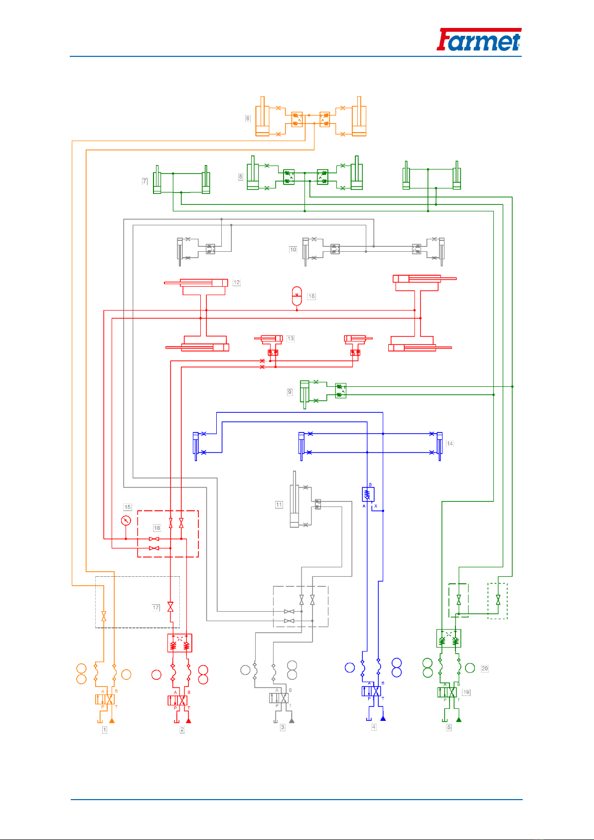
1.2. HYDRAULICS
Parts of the hydraulic system of the machine, which are under pressure, are forbidden to disassemble.
Hydraulic oil that penetrates the skin under high pressure causes severe injuries. In case of injury, seek a
physician immediately.
DESCRIPTION OF THE HYDRAULIC SYSTEM DIAGRAM
1. Yellow circuit
2. Red circuit
3. White circuit
4. Blue circuit
5. Green circuit
6. Hydraulic cylinders –axles
7. Hydr. cylinders –supporting cylinders, side frames
8. Hydr. cylinders –supporting cylinder, middle
9. Hydr. cylinder –hitch
10. Hydr. cylinders –levelling discs
11. Hydr. cylinder –support foot
12. Hydr. cylinders –side frame folding
13. Hydr. cylinders –frame securing against unfolding
14. Hydr. cylinders –front tools
15. Manometer
16. Pressure accumulator
17. Closing valve
18. Switching valve
19. Tractor distributor
20. Hydraulic couplers
Manual
FANTOM 850 PS
13 │33
DIAGRAM OF THE HYDRAULIC SYSTEM OF FX 850 PS:

Manual
FANTOM 850 PS
14 │33
2. MACHINE ASSEMBLY AT THE CUSTOMER
The operator must perform the assembly according to the instructions of the producer, best in
cooperation with the expert servicing technician determined by the producer.
The operator must secure a functional test of all assembled parts after the completion of the machine
assembly.
The operator must secure that the handling of the machine using lifting equipment during its assembly is
in accordance with chapter „C“.
3. COMMISSIONING
Before taking over the machine, test and check, whether damage occurred during transport and whether
all parts contained in the bill of delivery were supplied.
Before commissioning the machine, carefully read this operating manual, especially Chapters A-D. Before
the first use of the machine, familiarise yourselves with its controls and overall function.
During work with the machine, observe not only the instructions of this operating manual but also
generally valid regulations of work safety, health protection, fire and transport safety, and environmental
protection.
The operator must check the machine before every use (commissioning) from the standpoint of
completeness, work safety, work hygiene, fire safety, transport safety, and environmental protection.
A machine showing signs of damage must not be commissioned.
Aggregation of the machine with the tractor is to be performed on a flat and hardened surface.
When working on slopes, observe the lowest slope grade of the set TRACTOR - MACHINE.
Before starting the tractor motor, check whether no person or animal is in the working space of the set
and push the warning sound signal.
The operator is responsible for the safety and all damage caused by the operation of the tractor and the
connected machine.
The operator is obliged to adhere to the technical and safety regulations of the machine determined by
the producer when working.
The operator is obliged to retract the working bodies of the machine from the ground when turning at the
headland.
The operator is obliged to observe the prescribed working depths and speeds stated in the manual in Tab.
2when working with the machine.
The operator is obliged to lower the machine to the ground and secure the set against movement before
leaving the tractor cabin.
DECREASE OF SOIL PRESSURE TO A VALUE LOWER THAN 200 kPa
- To decrease the specific pressure on soil (below 200 kPa) at the turns on the headland, raise the machine
on the pole by using the hydraulic tractor shoulders and rear rollers. Turn around when the machine is
unfolded and resting on rollers.

Manual
FANTOM 850 PS
15 │33
3.1. AGGREGATION TO A TRACTOR
The machine can be connected only to a tractor, whose curb weight is identical or higher than the overall
weight of the connected machine.
The machine operator must observe all generally valid regulations of work safety, health protection, fire
safety, and environmental protection.
The operator may connect the machine exclusively to a tractor that is equipped with a rear three-point
suspension and a functional undamaged hydraulic system.
Tab. 4 –The table of requirements for the towing means for work with the machine:
(5) Requirement for the tractor engine power for cultivator FX 850 PS
245 - 370 kW
(6) Requirement for tractor
aggregation
(7) Spacing of the lower suspension joints
(measured at the joint axes)
1010±1,5 mm,
(possible to set also 910±1,5 mm)
(8) of the hole of the lower suspension
joints for the machine suspension pivots
37,5 mm
Bottom fixed hitch height
500 –600 mm (19.7 - 23.6 in)
Bottom fixed hitch aggregation
mechanism
Pin Ø50 mm (1.96 in)
Pin Ø70 mm (2.75 in)
Ball K80
(9) Requirement for the tractor's
hydraulic system
(10) Frame folding circuit
Circuit pressure 200 bar,
2 pcs of quick-coupler sockets
ISO 12.5
(11) Axle lifting circuit
Circuit pressure 200 bar,
2 pcs of quick-coupler sockets
ISO 12.5
Rollers lifting circuit
Circuit pressure 200 bar,
2 pcs of quick-coupler sockets
ISO 12.5
Front tool control circuit
Circuit pressure 200 bar,
2 pcs of quick-coupler sockets
ISO 12.5
Levelling disc circuit
Circuit pressure 200 bar,
2 pcs of quick-coupler sockets
ISO 12.5
Connect the machine using the TPS suspension bar to the lower arms of the rear TPS of the tractor, secure
the TPS arms using pins against disconnecting.
When connecting, no persons may stay in the space between the tractor and the machine.

Manual
FANTOM 850 PS
16 │33
3.2. HYDRAULICS CONNECTION
Connect the hydraulics only when the hydraulic circuits of the machine and the tractor (aggregate) are in
a pressure-less condition.
The hydraulic system is under high pressure. Regularly check for leaks and immediately remove obvious
damage of all lines, hoses, and pipe unions.
When seeking and removing leaks, use only the suitable tools.
For connecting the hydraulic system of the machine to the tractor, use the plug (on the machine) and the
socket (on the tractor) of the quick-couplers of the same type. Perform the connection of the machine
couplers to the tractor's hydraulic circuits so that the folding of the side frames –RED DUSTERS –was on
one control circuit, machine lifting on cylinders –GREEN DUSTERS –on the second control circuit, and
machine lifting on the axle –YELLOW DUSTERS –on the third control circuit, control of the levelling discs
and the storage feet –WHITE DUSTERS –on the fourth control circuit, and front tools –BLUE DUSTERS –
on the fifth control circuit.
In order to prevent accidental or foreign person (children, passengers) caused movement of the
hydraulics, the control switchboards on the tractor must be secured or blocked in the transport position.
Manual
FANTOM 850 PS
17 │33
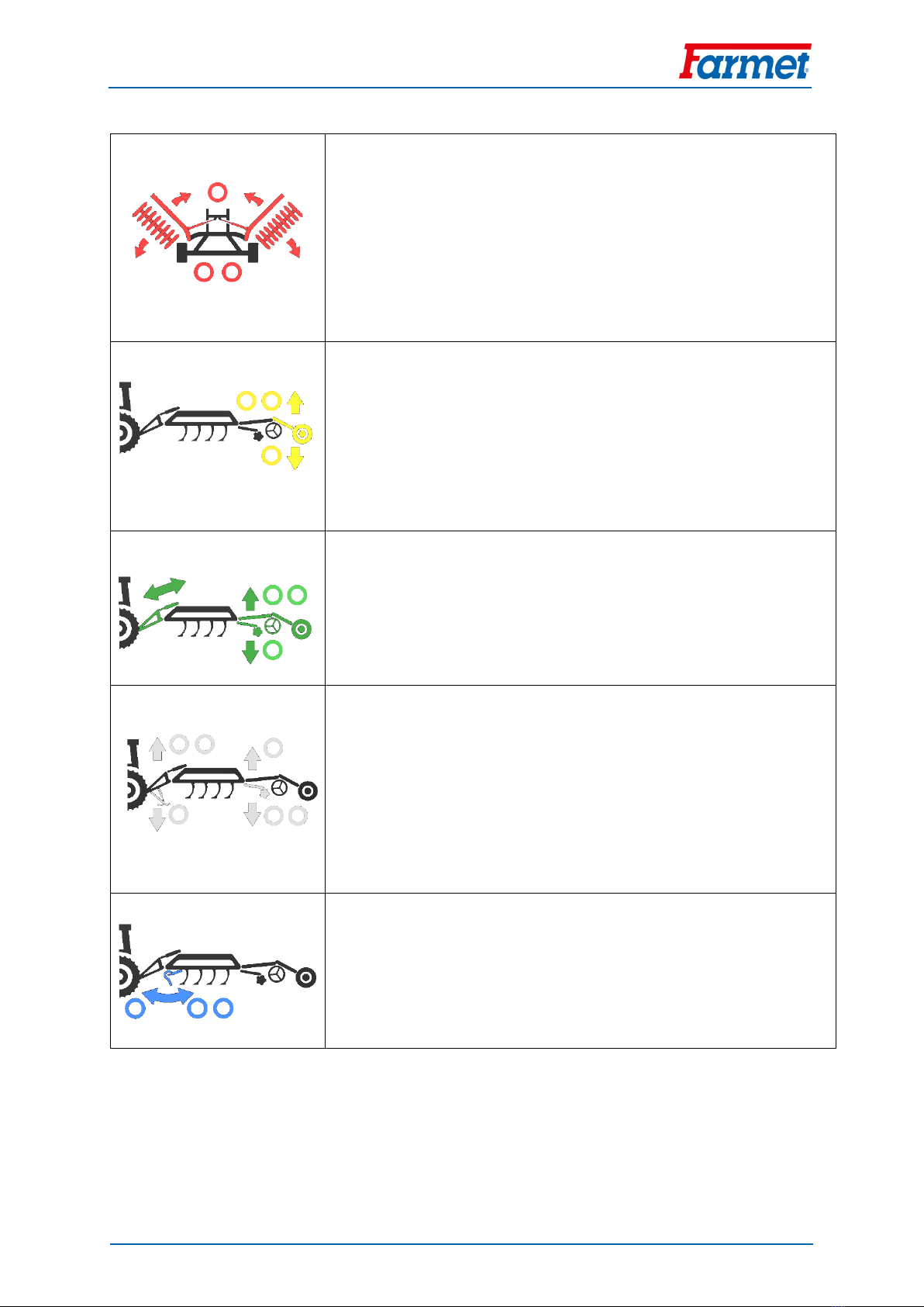
Fig. 3 –Hydraulic Circuits
RED DUSTERS –control of side frame folding and securing (after control
valve switching)
1 TAPE:
-folding the side frames into the transport position
-securing the frames against unfolding
2 TAPES:
-unfolding the side frames into the working position
-side frame release
YELLOW DUSTERS –axle control
1 TAPE:
-axle hydr. cylinder ejection, machine lifting into the transport
position
2 TAPES:
-axle hydr. cylinder insertion, machine lowering to the
ground, axle into the working position
GREEN DUSTERS –roller and tow bar control, headland turning
1 TAPE:
-hydr. cylinder ejection, machine shallowing
2 TAPES:
-hydr. cylinder insertion, machine deepening
WHITE DUSTERS –control of the levelling discs or the support leg (after
control valve switching)
1 TAPE:
-Covering disc hydr. cylinder insertion, disc shallowing
-Support leg hydr. cylinder ejection, tow bar lifting
2 TAPES:
-Covering disc hydr. cylinder ejection, disc deepening
-Support leg hydr. cylinder insertion, tow bar lowering
BLUE DUSTERS –front tools control
1 TAPE:
-hydr. cylinder insertion, front tools deepening
2 TAPES:
-hydr. cylinder ejection, front tools shallowing
Manual
FANTOM 850 PS
18 │33
3.3. HYDRAULICS CONTROL PANEL
On the tow bar, there is a control panel with up to 4 levers (according to machine equipment,
the number of levers may vary).
By moving the levers, spherical valves in hydraulic circuits are switched or closed.
The lever positions according to the pictograms drawn determine the specific settings of the
hydraulic circuits for the required machine function.
For better orientation, individual levers are also framed with colour according to the hydr.
circuits controlled by the lever in question.
With open closing valves, it is necessary to pay increased attention, unexpected machine
movement may occur.
When the machine rides on roads, it is necessary to have the machine locking lever for
transport in the LEFT position, i.e. locked.
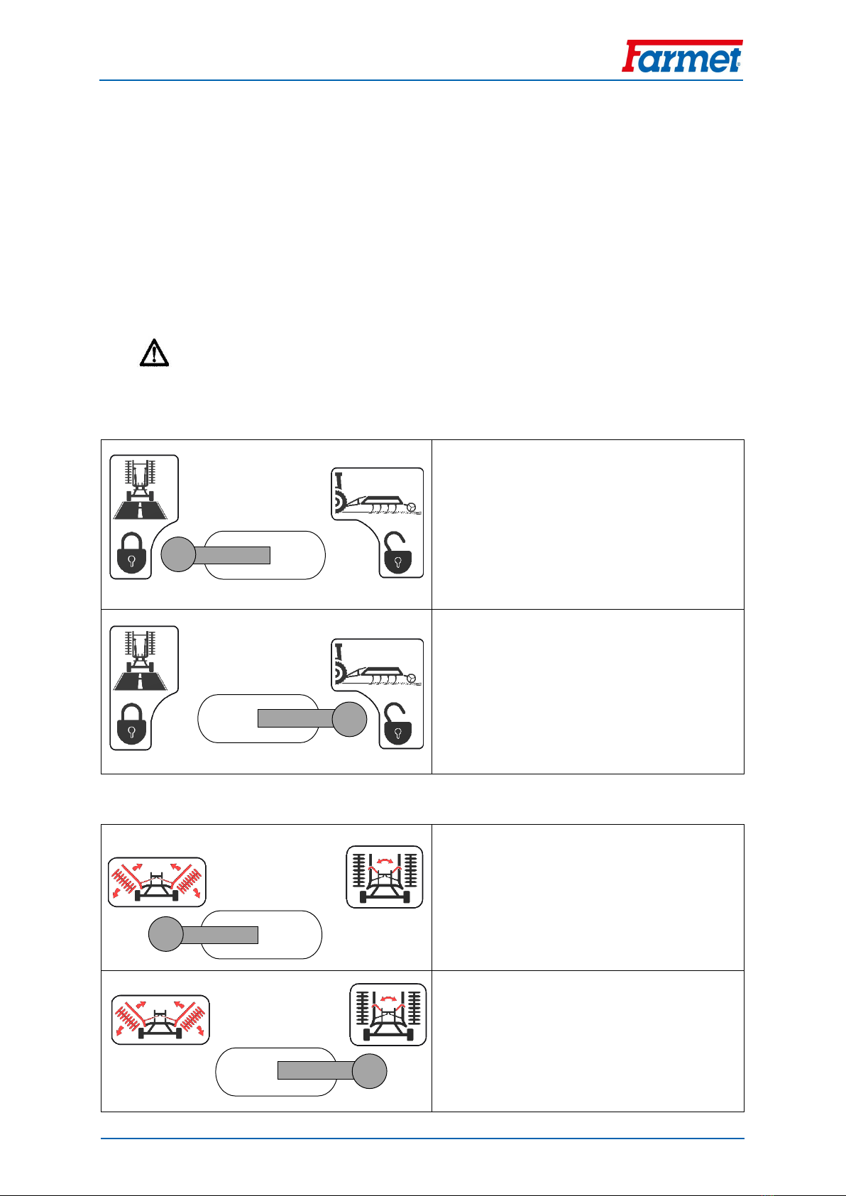
Machine locking lever for transport
Left lever position
The machine is brought into the transport
condition. The axle (yellow) and folding (red)
circuits are locked.
Right lever position
The machine is brought into the working condition.
The axle (yellow) and folding (red) circuits are open
and allow for free piston rod movement.
Attention! Unexpected machine movement
may occur upon switching.
Folding circuit function switching lever (red circuit)
Left lever position
The red circuit controls the side frame
folding.;
;
Right lever position
The red circuit controls the securing of the
side frames against unfolding.
Manual
FANTOM 850 PS
19 │33
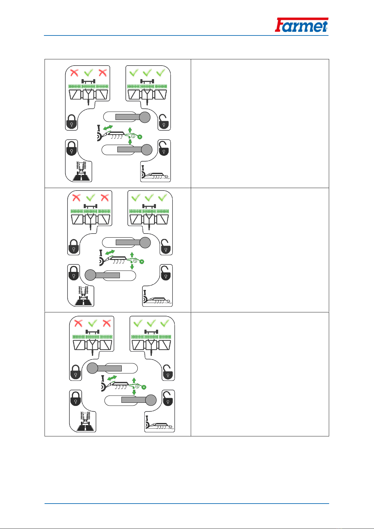
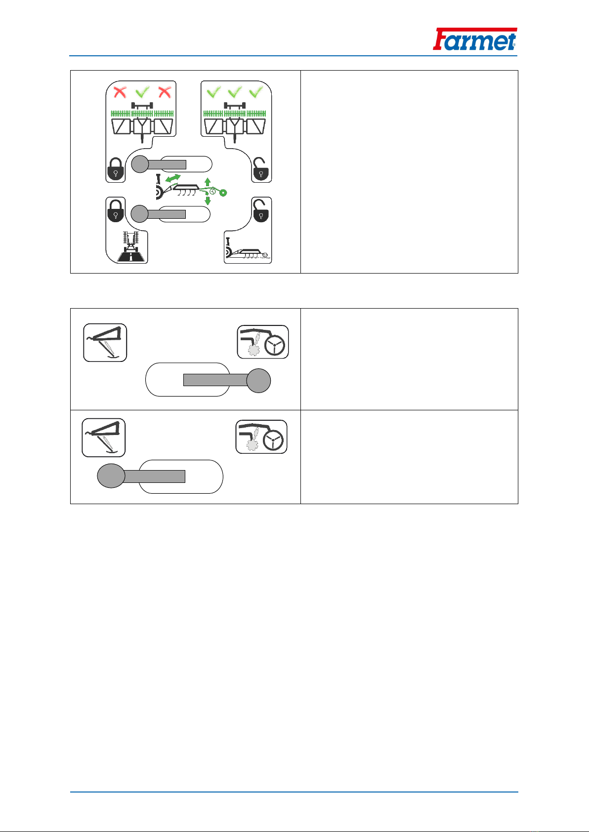
Roller circuit closing valve levers (green circuit)
Right lever position
The green circuit is open. The cylinder and tow
bar piston rods may move.
Used during work.
Attention! Unexpected machine movement
may occur upon switching.
Upper lever right, lower lever left
Upper lever –oil supply into the side roller
piston rods open
Lower lever –oil supply into the middle roller
and tow bar piston rods closed
Upper lever left, lower lever right
Upper lever –oil supply into the side roller
piston rods closed
Lower lever –oil supply into the middle roller
and tow bar piston rods open
Used for lifting on the axle to increase
clearance during crossing road unevenness.
Manual
FANTOM 850 PS
20 │33
Left lever position
The green circuit is closed. The roller and tow
bar piston rods cannot move.
Used during transport.
Covering disc circuit function switching lever (white circuit)
Right lever position
The white circuit controls the covering discs.
Left lever position
The white circuit controls the support leg.
Table of contents
Other Farmet Tiller manuals


