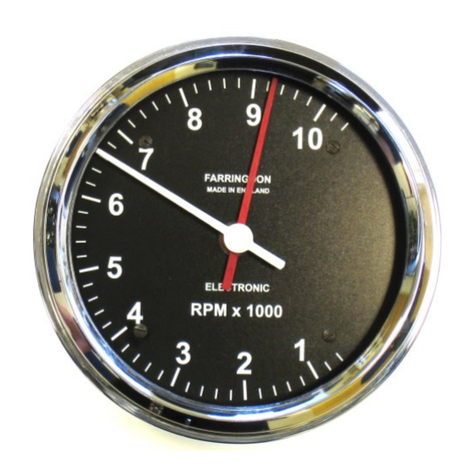
Farringdon RCA5 Series User manual

The RCA50 Series of Tachometers
Installation and Operating Instructions
Revision 8

Contents
Introduction and Outline Specification
2. Fitting Your Tacho
2.1 Mounting the Tacho
2.2 Connecting the Tacho
2.3 The Push Button
2.4 Shift Lights
3. Setting Up Your Tacho
3.1 Using the Push Button
3.2 Number of Cylinders
3.3 Tell-Tale and Other Modes
3.4 Ignition Pulse Filter
3.5 Shift Light Settings
3.6 Resetting the tell-tale.
4. Installing the Filter Unit (Older Models Only)
4.1 Purpose
4.2 Fitting
4.3 Commissioning
5. Troubleshooting

1. Introduction
The Farringdon RCA50 Series of tachometers are believed to be the first available with stepper
motor driven main and tell-tale hands. The tell-tale hand is a very useful feature especially when
used in its auto-reset mode and not just an extra hand to make it look more like historic
chronometric types.
Please read these instructions carefully and make sure that the tacho displays the correct rpm—if
set up incorrectly, it is likely to show double or half the rpm but it is possible to set it up so that it
shows 4/5th of the true rpm which might be very expensive!
Outline Specification
Supply Voltage
7 to 16 volts DC. Below 10
volts hand speed is reduced
Trigger Pulse
5 to 100 volts. Pulse width
greater than 10
microseconds
Supply Current
(mean)
Less than 100 mA without
shift lights, less than 150 mA
with shift lights
Accuracy
+/- 100 rpm or 1%
2. Fitting Your Tachometer
2.1 Mounting the Tachometer
The RCA50 tachometer is 80 mm in diameter, the RCA51 is 100 mm in diameter and the RCA52
120 mm and the hole in your dash should accept this diameter. It will require 60 mm behind the
dash to accommodate the depth of the instrument and the clamping studs.
An ‘O’ ring is supplied that may reduce vibration a little if it is fitted behind the bezel. Also it will
provide a compliance for the clamp to work against. If the dash is wood, then it is probably
unnecessary and will prevent the bezel from seating on the dash neatly.
In order to keep the overall depth of the instrument as small as possible, the mounting studs are
relatively short and therefore the U shaped clamp may have to be trimmed to accommodate thick
dash boards. The U clamp is steel but is easy to cut.

2.2 Connecting the Tachometer
The latest tachos have a small M8 connector and the back surface and are supplied with a
moulded mating connector with flying leads. These are connected as follows:
White
Ground or Earth
Connect this to a good chassis ground
Red
12 volt Supply
Connect to a fused 12 volt supply from master switch
(preferred) or ignition switch
Brown
Trigger
Negative side of coil or to dedicated tacho output from
engine ECU
Green
Shift Light 1 or Tell-Tale
Enable
Supplied shift light ONLY positive or 52 mm gauge tell-tale
enable.
Yellow
Shift Light 2
Supplied shift light positive ONLY
Grey
Push button
Connect to one side of push button
Pink
Push Button
Connect to other side of push button
Blue
Back lighting
Lighting 12 volts
Older tachometers are supplied with flying leads so that you canfit the connector of your choiceto
the car loom. The table lists the functions of the five free wires.
Black
Ground or Earth
Ground or Chassis
Red
12 volt Supply
A fused 12 volt supply from the master switch or Ignition if
there is no master switch
Violet
Trigger input
Negative side of coil or to dedicated tacho output from
engine ECU
Grey
Shift Light 1 Output
Supplied shift light ONLY or 52 mm gauge tell-tale enable
Blue
Shift Light 2 Output
Supplied shift light ONLY
Orange
Backlighting
Lighting 12 volts
Black/White and Red Wires
Connect the black wire to a good earth point and the red to a suitable switched and fused 12 volt
supply. A fuse of 1 amp is sufficient. The tacho requires a few seconds to power up so
connecting it to the master switch is preferable to the ignition supply.
On powering up, the tacho drives both hands forwards and then backwards into stops. After this
the tell-tale hand moves to the maximum rpm recorded since it was last reset.
Violet/Brown Wire
The trigger input can be connected to the switched end (-) of the coil directly or through the
supplied Filter Box for older tachos but if there is a dedicated tacho pulse from the ignition system
this would be better. If you are using a modern engine management system, you may need a 3.3

K resistor between this wire and +12 volts. If you have a rev. limiter fitted, then it is much better
to provide a separate trigger that isindependent from the ignition. (Please contact Farringdon for
advice on sensors that you can fit to your engine for this purpose. When the engine is running
faster than the rev. limiter should allow (on a change down at too higher road speed for example),
the ignition pulses are very irregular and will cause the tell-tale to record an incorrect (usually off
the scale!) figure. Apart from alarming you, you will not be able to make sensible decisions about
any damage that may have been caused to the engine.
Blue and Grey Wires or Green and Yellow
Connect these wires to the red wire of the shift light. Connect the black or blue wire of the shift
light to ground. The shift light outputs are positive 5 volt, 50 mA signals that are designed to
drive the LED shift lights supplied by Farringdon. Do not connect filament type lights to these
outputs—it will not drive them!
Orange/Blue Wire
Connect this to the lighting supply - a supply that switches to 12 volts when the lights are on.
2.3 The Push Button (Grey and Pink wires)
The push button should be mounted where you can reach it while being able to readthe tacho. If
other people are going to drive the car you may wish to put it somewhere hidden so that the
tell-tale cannot be reset easily! The push button requires a 12 mm diameter hole. Fit the
sealing cap to keep moisture out of the switch.
2.4 The Shift Lights
The supplied shift lightsshould be fittedwhere they will catch your eye while youare looking at the
track or road. Try various places (holding them in place with tape) before deciding where to
mount them. The black plastic bezels push into the dash from the front and are held in place
when the LEDs are inserted from the back. The hole size for the bezels is 14 mm diameter.

3. Setting Up Your Tachometer
There are five settings that must be adjusted before you can use the tacho. These are
1. The number of cylinders or pulses form the engine for every two turns of the engine
2. The mode of operation. This is mainly the tell-tale reset mode
3. The trigger pulse filter. This allows you to use a wide range of pulse widths for the trigger
input.
4. The rpm at which shift light 1 comes on and the rpm at which shift light 2 comes on and
both lights flash.
To revert to factory setup, enter setup mode by turning on the tacho with the button pressed,
release the button and then press it again for 20 seconds.
3.1 Using the push button
Having the tell-tale hand makes setting up very easy as the red tell-tale hand shows what you are
setting up and the white main hand shows the value of the setting. The button is used to
increase the value of the setting, with a quick push, to decrease the value with a push of about 2
seconds and to go on to the next setting with a push of 5 seconds. You will find this easier than
it sounds!
In the following paragraphs, numbers refer to the first digit on the tacho scale; e.g. when setting
the cylinders to 4, the white hand has to be set to 4000 rpm however this is marked, maybe 4 or
40.
To enter set up mode, hold the push button down and then apply the power. The tell-tale needle
will move to 1 (the first set up item) and the main hand will show the currently set no of cylinders.
When the needles have stopped moving, release the button.
3.2 Number of Cylinders (tell-tale at 1)
In order to allow for uneven firing engines, Farringdon uses thenumber of trigger pulsesin two full
turns of the engine to calculate the rpm. Unless you have a special sensor, this is likely to be the
number of cylinders connected to the coil you are using.
Use the push button to increase or decrease the number shown by the main hand until it is
correct. Then hold the push button pressed for 5 seconds to move on to the next set up item.
Note. If the red hand indicated 1500 rpm, this shows that the number of cylinders has been set to
the max and has wrapped over. E.g If the red hand is on 1500 rpm and the white on 4000 rpm,
then the tacho has been set to 8+4 (for a 0 to 8000 tacho) cylinders. Press the button for 20
seconds to start again from the factory setting.

3.3 Mode (tell-tale at 2)
The following table shows the value to set for the mode:
Mode
Tell-Tale
Trigger Pulse
Chromometric
0
Auto reset
Negative
No
1
Manual
Negative
No
2
Auto reset
Positive
No
3
Manual
Positive
No
4
Auto reset
Negative
Yes
5
Manual
Negative
Yes
6
Auto
Positive
Yes
7
Manual
Positive
Yes
Tell-Tale Modes
The tell-tale needle on original chronometric tachometers was mechanically pushed to the highest
reading reached by the main hand. The tell-tale could be reset by pushing a small button on the
side of the instrument. This is copied in the manual reset mode. The auto reset mode resets
the tell-tale hand after about two seconds back to follow the main hand. This is very useful as it
gives the driver time to see what the engine was revved to before or during each gear change.
Trigger Pulse Polarity
This may need to be changed to match the pulse from a special sensor. For ignition coil
connected wiring set it to positive.
Chronometric Action
If this option is selected with settings 4,5,6 or 7, the tacho moves the main needle once every half
second in the manner of the original mechanical chronometric movements. This action is
switched off after reaching 5000 rpm for 0 to 8,000 and after reaching 6,000 rpm for the 0 to
10,000 and 12,000 versions.
Once you have adjusted the mode setting, hold the push button pressed for five seconds.
3.4 Trigger Pulse Filter (tell-tale at 3)
The trigger pulse filter sets the shortest electrical pulse to which the tacho will respond. For
ignition connected wiring, set this to 7 and only reduce it if the tacho does not read over a certain
rpm. For special sensor systems, set this to 1 as a first try. If the needle starts to jump up when
the engine is running under load, try increasing the filter setting.
After setting the filter, push the button for 5 seconds to save the setting

3.5 Shift Light Settings (tell-tale at 4 and 5)
The next two settings are for the shift lights. Use the push button to set the rpm at which you
would like the first and second shift lights to illuminate. Remember to hold the push button
pressed for 5 seconds after each adjustment to move on to the next. After the last shift light is
set, the tacho will initialise as if it had been switched on.
3.6 Resetting the Tell-Tale
In auto reset mode, the maximum rpm recorded is shown after switch on and the hands have
been driven into the stops. To reset this value, or the tell-tale hand when in manual mode, simply
press the push button after the tell-tale reading has been shown.
Important Notes
Further steps in the set up process can be skipped at any time by switching off the tacho
but only the settings that have been terminated with the 5 second long push button press
will be saved.
If you increase a setting so that it reaches the maximum on the scale, it will “wrap” round
to 1 if the setting is increased again. This allows you to set up a 16 cylinder engine on a 0
to 8000 rpm dial. When this wrap occurs, the tell-tale hand steps on half a division to
indicate that this has happened.
****** To set the tacho back to the factory settings (4 cylinders, mode 4, filter 4, shift
lights 7000 and 8000 rpm), enter set up mode and press button for 20 seconds. ******

4. The Filter Unit. (not applicable to newer models)
4.1 Purpose
The Tacho Filter Unit is a simple filter contained in a small plastic box that may be required when
using a Farringdon RCA5x Tacho with contact points ignition systems. It may be of use with
some electronic systems as well. Essentially the unit filters the signals taken from the negative
(on negative earth systems) side of the coil. These signals carry considerable noise from the
arcing inside the distributor cap. Many other tachos have this filtering included but this prevents
them from working with very short pulses that can come from directly triggering from a sensor on
the flywheel.
4.2 Fitting
Mount the unit at least 25cms away from the distributor. The components in the plastic box
are “potted” so it can be mounted in the engine bay.
a) Connect the violet wire of the filter unit to the violet wire of the tacho.
b) Connect the black wire of the Filter Unit to ground.
c) Connect the negative of the coil to the green or blue wire. The blue input provides more
filtering than the green so start with the green wire.
Temporarily insulate the unused blue or green wire.
4.3 Commissioning
Set the tachofilter setting to 8. See Section 3.4for details of howthis is done. Try the tachoand
check that the needles do not jump about (+ or –500 rpm or so) when the engine is held at a
steady 3000 rpm. If the needle is steady, try at full speed under load.
If either needle makes jumps to higher rpm when the engine is running at a constant speed,
increase the filtering by connecting the trigger wire to the blue instead of the green filter wire.
If the needles are steady, then try changing the tacho filter setting to 7. This will make the tacho
more responsive.
Warning DO NOT rely of the tacho reading until you are certain that you have set it up
correctly and that it is showing the correct rpm..

5. Troubleshooting
To set the tacho back to the factory settings (4 cylinders, mode 4, filter 4, shift lights 7000
and 8000 rpm), enter set up mode and press button for 20 seconds.
Farringdon Instruments Limited .The Old Stables, Manor Farm,
West Worldham. ALTON .
Hampshire GU34 3BD. Telephone 01420 541591.
www.farringdoninstruments.com
Symptom
Possible Cause
Fix
No movement of tacho
hands when turned on
No power
Check for +12 volts between red and black
wire.
Tacho runs against
stop on power on but
shows no rpm
No or incorrect
trigger pulse
Make sure that the trigger pulse is greater
than 5 volts and falls to less than 0.2 volts.
Set trigger pulse filter to 1
Tacho does not show
correct rpm
Trigger pulse setting
is incorrect
Check set up. Set to factory setup (start of
section 3) and start again. Call Farringdon
for help.
Main hand drops to 0
above a certain rpm
Filter setting is too
high
Reduce filter setting
Main hand is unsteady.
Irregular trigger or
too short trigger
pulses.
Increase filter setting or fit Filter Unit
Shift Lights do not work
Lights wired
incorrectly. Shift
RPM setting wrong
Make sure the shift lights are wired correctly
Black to black. Check RPM settings for Shift
Lights.
This manual suits for next models
4
Table of contents
Other Farringdon Measuring Instrument manuals
Popular Measuring Instrument manuals by other brands

DAKOTA ULTRASONICS
DAKOTA ULTRASONICS MX-3 Operation manual

RS PRO
RS PRO RS-137 instruction manual

Lufft
Lufft E200IR operating manual

Niigata seiki
Niigata seiki WCDI-50 instruction manual

elsner elektronik
elsner elektronik KNX TH-UP basic Installation and adjustment

PCB Piezotronics
PCB Piezotronics JM352C18 Installation and operating manual