FarSounder FarSounder-500 User manual

FarSounder, Inc. F31552 (Rev. 2.6.1) Page 1 of 56
Operation Manual
FarSounder-500, FarSounder-1000 and FS-3DT Sonar Systems
FarSounder, Inc.
43 Jefferson Blvd.
Warwick, RI 02888
United States
phone: +1 401 784 6700
fax: +1 401 784 6708
www.farsounder.com
Copyright ©2006-2012 FarSounder, Inc.
FarSounder is committed to providing the best quality and performance possible with our
products. As part of this policy, all information herein is subject to change as new and
improved versions of our software and hardware are released.
FarSounder, the FarSounder logo, Power Module, Transducer Module, and SonaSoft are
trademarks of FarSounder, Inc.
"Jeppesen", "Jeppesen Marine", "Jeppesen OnBoard", and "C-Map" are trademarks of
Jeppesen Sanderson, Inc.

Operation Manual
FarSounder, Inc. F31552 (Rev. 2.6.1) Page 2 of 56
Table of Contents
1. Installation of Shipboard Equipment .............................................................................................. 4
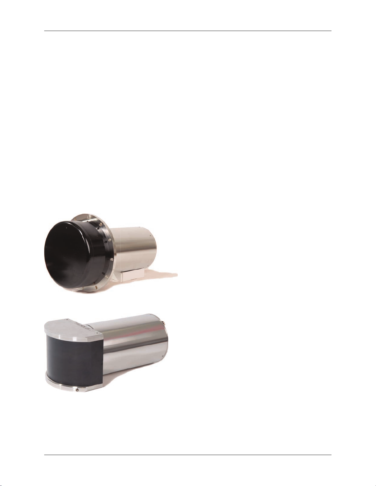
1.1. Transducer Module ........................................................................................................... 4
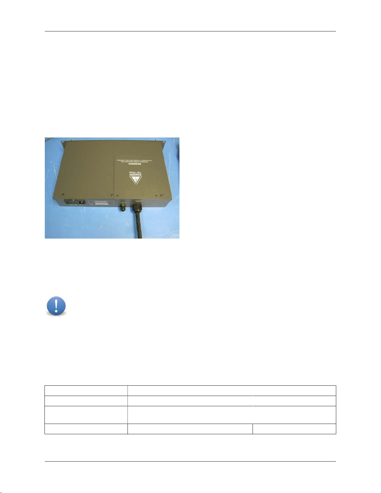
1.2. Power Module .................................................................................................................. 7
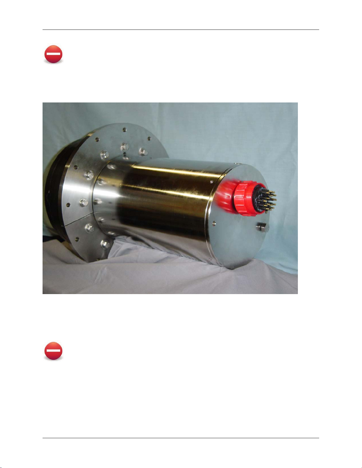
1.3. Transducer Module Connection Cable ................................................................................ 9
1.4. Network Connections ...................................................................................................... 12
1.5. Installing the SonaSoft™ Software ................................................................................... 13
1.6. External Sensor Connections ........................................................................................... 14
1.7. Operating the Sonar ........................................................................................................ 14
2. SonaSoft™ User Interface Computer Requirements ..................................................................... 16
2.1. Overview ........................................................................................................................ 16
2.2. Minimum Requirements for FS-3DT, FarSounder-500, and FarSounder-1000 systems ........ 16
3. The User Interface Workspace ................................................................................................... 17
3.1. Overview ........................................................................................................................ 17
3.2. Managing the Sidebar Workspace .................................................................................... 17
3.3. Using The Application Buttons ......................................................................................... 18
4. First Time Configuration ............................................................................................................. 22
4.1. Overview ........................................................................................................................ 22
4.2. Connecting NMEA Devices .............................................................................................. 22
4.3. System Settings Options ................................................................................................. 25
4.4. Chart Set Up .................................................................................................................. 26
5. The 3D Sonar Display ................................................................................................................ 27
5.1. Overview ........................................................................................................................ 27
5.2. 3D Volumetric/Standard View .......................................................................................... 27
5.3. Profile View .................................................................................................................... 28
5.4. Forward Looking Alarm Use ............................................................................................ 29
5.5. Menu Bar Controls .......................................................................................................... 30
5.6. Mouse Controls ............................................................................................................... 31
5.7. 3D Sonar Processing Options .......................................................................................... 31
5.8. Control Settings Examples ............................................................................................... 33
6. Chart Display ............................................................................................................................. 38
6.1. Overview ........................................................................................................................ 38
6.2. Chart Overlay Explained .................................................................................................. 38
6.3. Menu Bar Controls .......................................................................................................... 39
6.4. Mouse Controls ............................................................................................................... 39
6.5. Configuration Manager Options ........................................................................................ 39
6.6. Requirements .................................................................................................................. 41
7. Nav Info Display ........................................................................................................................ 42
7.1. Overview ........................................................................................................................ 42
7.2. Configuration Manager Options ........................................................................................ 42
8. Using the Export Option ............................................................................................................. 44
A. Understanding Interference and Other Limitations ....................................................................... 45
1. Overview ........................................................................................................................... 45
2. Other Sonar Interference .................................................................................................... 45
3. Bubble Cloud/Wake Interference ......................................................................................... 47
4. Sea State Limitations ......................................................................................................... 48
5. Vessel Speed Limitations ................................................................................................... 49
B. Understanding Water Depth Performance ................................................................................... 50
C. Maintenance ............................................................................................................................. 53
1. Overview ........................................................................................................................... 53

Operation Manual
FarSounder, Inc. F31552 (Rev. 2.6.1) Page 3 of 56
2. Every 3 Months ................................................................................................................. 53
3. Every 6 Months ................................................................................................................. 53
D. Troubleshooting ......................................................................................................................... 54
1. Overview ........................................................................................................................... 54
2. Power Module LED Descriptions ......................................................................................... 54
3. Power Module LED Diagnostics .......................................................................................... 54

Operation Manual
FarSounder, Inc. F31552 (Rev. 2.6.1) Page 4 of 56
1. Installation of Shipboard Equipment
Before running the software, it is important that the equipment has been properly installed by the shipyard
or electronics integrator. This chapter summarizes the installation process and serves as a guide for the
ship operator for confirming proper installation.
Your sonar system consists of:
•Transducer Module
•Power Module
•Transducer Module Connection Cable
•SonaSoft™ software
Generally, the equipment is installed by the ship yard and/or electronics integrator.
1.1. Transducer Module
The most obvious component in your sonar system is the Transducer Module. Though different models are
supplied with the FarSounder-500 and FarSounder-1000, the installation concepts discussed here are the
same for all Transducer Modules.
Figure 1. FarSounder-500 Transducer Module
Figure 2. FarSounder-1000 Transducer Module
The Transducer Module should be installed as far forward and as far below the water as possible on the
vessel. The black urethane array face should be facing forward with a clear view of the water ahead of the
vessel. On the face of the unit there is a small protrusion to indicate the 12 o'clock position of the unit. The
Transducer Module must be installed with this marking at the 12 o'clock position for proper operation.

Operation Manual
FarSounder, Inc. F31552 (Rev. 2.6.1) Page 5 of 56
Warning
Do not open the transducer module. Injury or death may result. There are no user serviceable
parts inside.
The Transducer Module has a single underwater matable connection. This connector is used to connect the
Transducer Module to the Power Module via FarSounder's Transducer Module Connection Cable. When
properly installed, the face protrusion and the rear connector should be at the 12 o'clock position.
Figure 3. Rear view of Transducer Module. Apply o-ring grease to only the rubber base of the connetor pins.
The connector can be connected dry or underwater. Before connecting, a small amount of silicon O-ring
lubricant should be put around the black rubber portion of the pins on the Transducer Module's mating
connector. If connecting underwater, lubricant may not be necessary.
Warning
Do not get the lubricant on the metal conductor pins.
The wet end connector should not be left unconnected while wet or underwater for extended periods of
time. A Connection Cable End Cap (F24557) is supplied as standard for use during transport/installation
and extended periods of unconnected wet or underwater use.
Installation
The Transducer Module has been designed to allow for a simple, one cable connection to the rest of the
sonar hardware. Twelve holes are located around the Transducer Module's flange to allow for mechanical

Operation Manual
FarSounder, Inc. F31552 (Rev. 2.6.1) Page 6 of 56
attachment to the vessel. The connector on the rear of the Transducer Module is capable of a wet mating
and un-mating. If necessary, this allows the Transducer Module to be installed and removed from the vessel
by a diver underwater, rather than dry docking or hauling the vessel. Here are the primary steps for installing
the Transducer Module into a pre-installed fairing mount.
1. Unpack the Transducer Module. Ensure that there is no debris caught in the connector pins.
2. Dab a small amount of silicon o-ring grease on the rubber sleeve of each connector pin (on the
Transducer Module). Be sure not to get any grease on the pins themselves.
3. If the installation is done underwater, a blank connector cover should have been used on the
Transducer Module Connection Cable's wet end connector. Remove the blank connector cover from
the cable.
Figure 4. Remove connector cap from cable
4. Connect the Transducer Module Connection Cable to Transducer Module. Be sure that the connector
is fully connected. The black rubber on the cable and the Transducer Module connectors should be
flush with each other.
5. Hand tighten the red connector locking collar on the cable and Transducer Module.
Figure 5. Connect cable and locking ring
6. Connect the Transducer Module in to your installation mount. You should use all 12 bolts if possible.
Bolts are not included.
When installing the Transducer Module into your mount, the orientation of the Transducer Module is very
important. There is a protrusion on the black urethane face on the front of the unit that should be at the
12 o'clock position. The connector on the rear of the Transducer Module should also be at the 12 o'clock
position. As with any piece of bolted hardware, the use of washers and lock washers is recommended.
Important
Do not put caulking (such as Sikaflex) around the Transducer Module. It is important that water
beabletoflowthroughthesmallslitsintheinstallationcollarinordertohelpwithsystemcooling.

Operation Manual
FarSounder, Inc. F31552 (Rev. 2.6.1) Page 7 of 56
The standard material for the Transducer Module pressure case is SS 316. To ensure the longest
operational life of the unit, it is recommended that the Transducer Module is not electrically isolated from
the rest of the vessel and that zincs are closely located to the Transducer Module. As with any other piece
of marine electronics, it is important to ensure that the Transducer Module does not become anodic (active)
relative to closely located materials.
Forcompositehulls,it is importantthattheTransducerModule is connectedtotheship's ground. Theismost
easily attained by connecting the fairing's inner mounting ring (generally this is a steel flange embedded
into a composite fairing) to the ship's ground.
Additionally, it is recommented that the Transducer Module be electrically connected to zincs. The simplest
way to do this on a composite hull is to weld a ground strap from the fairing's mounting flange to a hull
mounted zinc plate.
Another method is to attach zincs directly to the Transducer Module outside of the fairing. This can most
easily be implemented by using two (2) of the twelve (12) mounting bolts to secure zincs between the fairing
tube and the side of the urethane array face. This allows the zincs to be inspected and replaced by diver
without removing the Transducer Module.
Important
If painting the Transducer Module, be certain NOT to paint the urethane array face. Also, be
certain that the paint used will not dissolve, destroy, or otherwise harm the urethane since it is
likely that some paint will touch the edge of the urethane array face.
1.2. Power Module
FarSounder's Power Module is offered in a bulkhead mounted enclosure or a standard 19" 2U rack-mount
component. Both are designed to be mounted in a dry location. The Power Module houses the sonar
system'spowersupplies,transmitsignalgenerator,andpoweramplifier.Aswithothershipboardelectronics,
the unit should be shock mounted where appropriate. Shock mounting will generally improve the lifespan
of the unit and should be considered for installation locations that experience extreme shock or vibration.
However, this is not a standard requirement.
Figure 6. Power Module (rack mount version)
The Power Module should be located in a dry location. There are no user interface components on the
Power Module other than a power switch. For installation in inaccessible locations, the power input can be
put on a circuit breaker line with the switch in a convenient location.
Warning
Do not open the Power Module or allow it to get wet. Injury or death may result. There are no
user serviceable parts inside.

Operation Manual
FarSounder, Inc. F31552 (Rev. 2.6.1) Page 8 of 56
Plugs and Connections
The Power Module has three connections that are necessary for operation: a Transducer Module
Connection Cable, a network connection, and a power connection.
The Transducer Module Connection Cable enters the chassis via the large circular cable gland on the back
of the Power Module's chassis. The Transducer Module Connection cable is the largest of the cables and
requires the most clearance. The Transducer Module Connection cable should have a soft layup entering
the Power Module. The recommended minimum cable bend radius is 6 inches (15 cm). Therefore, 8 to 10
inches (20 to 25 cm) minimum clearance behind the Power Module is recommended. FarSounder is not
responsible for damage to the cable due to excessive bending. Standard cable/wire anchors or ties can be
used to support/secure the cable to any bulkheads or mounting hardware as necessary.
Figure 7. Transducer Module Connection Cable entry into rack mount Power Module.
The Power Module is powered by either 110-120 or 220-240 VAC. Total power consumption for the unit is
approximately 100 watts continuous. A power receptacle (IEC-320-C14 inlet socket) is used to connect AC
mains power to the Power Module. The recptical includes a replaceable fuse, line filter and a master power
switch.It is recommendedthat anUninterpretable Power Supply (UPS) beused topower the PowerModule.
Important
If the Power Module is located in a location that is not easy to access, it is recommended that
a dedicated circuit (with circuit breaker in the main bridge circuit breaker panel) be used for the
Power Module. This will allow the user to turn off the Power Module remotely.
The Power Module has a standard RJ-45 plug for connecting to the user interface computer. The Ethernet
cable enters the chassis via the smaller circular cable gland. When connecting the Power Module directly
to the user interface computer, an Ethernet cross-over cable should be used. If the Power Module is going
to connect to a network switch before connecting to the user interface computer, a standard Ethernet
patch cable may be used. It is not recommended that the Power Module share a network switch with other
high-bandwidth network devices. See section on Network Connections for more information.
Connection Type On Power Module Mating Connectors
Power IEC-320-C14 inlet socket IEC-320-C13 connector plug
Transducer Module BNC, RJ-45, terminal blocks for stranded
wire BNC, RJ-45, discrete wires
Network RJ-45 socket RJ-45 plug
Table 1. External Connections to Power Module

Operation Manual
FarSounder, Inc. F31552 (Rev. 2.6.1) Page 9 of 56
Indicator Lights
There are seven indicator LED's on the front of the Power Module casing. From left to right they are: TX
Off, Fault, Ctrl A, Ctrl B, Ping, Bank 1, Bank 2. (Older versions of the Power Module may not include the
TX Off or Fault indicators.)
1. TX Off - Indicates that the power amplifier is deactivated. This can be set by the slider switch on the
front panel (rack mount version) or internal (bulkhead mount version) and used for testing the unit
while in dry-dock.
2. FAULT - Indicates that the power amplifier is deactivated. This can be set by the slider switch on the
front panel and used for testing the unit while in dry-dock.
3. CTRL A, CTRL B - Indicates internal Power Module logic states. These are used for debugging
purposes only and have no user application. The state of these LED's may change from time to time
depending upon the particular mode setting of the sonar system. Once the Transducer Module has
booted, these indicators will blink until the user interface communicates with the Transducer Module.
4. PING - Flashes every time the sonar transmits a ping.
5. BANK 1, BANK 2 - Indicates power amplifier capacitor banks are changed. These indicators may
remain lighted for a short period of time after the unit is powered down.
Installation
The Power Module can be installed in any dry location within 100 feet of the Transducer Module. There
are no user interface components on the Power Module other than a power switch. This means that even
though it has blinking lights, it does not need to be located in a convenient to access location.
Warning
Make sure the Power Module is switched off before connecting to the Transducer Module.
Warning
The Power Module is not water tight and should not be located in an area with condensation.
1.3. Transducer Module Connection Cable
FarSounder's Transducer Module Connection Cable is a custom made cable designed to connect a
FarSounder Transducer Module to a FarSounder Power Module. The wet end connector can be connected
dry or under water. Before connecting the wet end connector, a small amount of silicon o-ring grease should
be put around the black rubber portion of the pins on the Transducer Module's mating connector. Do not
get the grease on the metal conductor pins.
The wet end connector should not be left unconnected while wet or underwater for extended periods of
time. A wet end connector cap is shipped with the cable for use during extended periods of unconnected
wet or underwater use.
This documentation is given as a reference only. This cable is supplied by the Manufacturer and should
not be serviced by the end user.
Cable Specification
•Maximum Length: 100 feet (33 meters)

Operation Manual
FarSounder, Inc. F31552 (Rev. 2.6.1) Page 10 of 56
•Approximate OD: 0.8" (2 cm)
•Jacket Material: Water-proof, Low Temperature Polyurethane
•Minimum Bend Radius: 6" (15 cm)
Cable can be cut to length on location. It is recommended that at least 3 feet (1 meter) extra cable length
be coiled at the Power Module if cutting to length.
Dry End Preparation
Connections to the dry end of the Transducer Module Connection Cable are made inside the Power Module.
The rack mount Power Module has a removable access panel on the top of the chassis towards the rear of
the unit. Removal of this panel allows access to the Power Module's cable interface as well as its ROM. On
the bulkhead mount version of the Power Module, the entire top pannel can be removed for access.
After passing the Transducer Module Connection Cable through the cable gland, the cable should be
prepared as shown in the figure. The urethane jacket and braided shield should be removed about 7.5"
(19 cm) from the end of the cable. This will expose the bundled wires. Be sure not to damage the internal
conductors. The Cat-5 cable to the bridge should be prepared for a standard Ethernet connection. Note that
all of the conductors from the Transducer Module Connection Cable will fit through the gland even with the
BNC and RJ-45 connectors installed.
Figure 8. Example termination inside rack mount Power Module
Terminating the Cat-5 Cable
StandardT568B wiring should be used for the Cat-5 cable coming out of the Transducer Module Connection
Cable bundle. It is recommended that the Ethernet cable used to connect the Power Module to the bridge be
a standard straight-through cable also using T568B wiring. Use standard RJ-45 connectors on this cable.
These connectors are not supplied by FarSounder.
Terminating the Coax Cable
The coax cable is terminated with a standard BNC crimp style connector. There are many varieties of
theseconnectorsdepending upon theparticular cable specifications.FarSoundersupplies aBNCconnector

Operation Manual
FarSounder, Inc. F31552 (Rev. 2.6.1) Page 11 of 56
suitable for the supplied cable with the Power Module. Standard coax preparation tools can be used to strip
the coax jacket and conductor. A standard BNC crimping tool can be used to install the connector.
Figure 9. Crimp terminating the coax cable
Recommended Tools
Listed below are the tools that FarSounder uses though many equivalent tools exist.
Description Use Manufacturer MFR Part Number
Rotary Cable Stripper Removing outer jacket of sonar
cable Tyco 606700-1
Coax Cable Stripper Prepping Transmit Coax in sonar
cable Paladin Tools LC CST 1255
BNC Ratchet Crimper Terminating Transmit Cable BNC Tyco 58433-2
Table 2. Recommended Cable Termination Tools
Terminating the Individual Conductors
The six individual conductors are connected to the Power Module using standard terminal strips. No
connectors are required.
Mating the Connections
Connect the BNC and RJ-45 to their respective receptacles on the Power Module's circuit board. Follow the
labels on the pcb to ensure that each RJ-45 is connected to the correct receptacle.
Connect the remaining conductors to the circuit board via the terminal strips. The four 16 gauge conductors
fit into one terminal strip block. The two 12 gauge conductors fit into another terminal strip block. Follow the
color codes on the circuit board to ensure that each conductor fits into the correct receptacle. Note that the
12 gauge conductors fit very snug into the terminal strip block. Make sure that the strands of the conductor
are not separated. Otherwise it will be difficult to ensure a proper connection.

Operation Manual
FarSounder, Inc. F31552 (Rev. 2.6.1) Page 12 of 56
Figure 10. Minimize strain on wires
Wet End Preparation
The wet end of the cable is terminated with a Subconn BH16MSS connector. This connector is molded
on to the cable at the factory and cannot be serviced by the user. This connection can be mated in a wet
environment or underwater. Prior to connecting this to the Transducer Module mate, apply o-ring grease
to the black portion of the pins on the Transducer Module. The wet end connector is approximately 2.4
inches (6 cm) in diameter.
Warning
This connector can be mated and un-mated underwater as long as the Power Module is
switched off. If this connector is to be left un-mated in a wet environment or underwater, it is
necessary to protect it using the supplied Connection Cable End Cap.
Figure 11. Remove connector cap from cable
1.4. Network Connections
FarSounder's sonar systems operate on a standard Ethernet network using TCP/IP protocol layers. It is
recommended that 1Gb Ethernet network hardware be used.

Operation Manual
FarSounder, Inc. F31552 (Rev. 2.6.1) Page 13 of 56
Due to the high bandwidth needs of the FarSounder systems, it is also recommended that the Ethernet
network be private. That is to say that for best performance results, the network should not be shared with
other non-FarSounder network traffic. A private network can be established by keeping the network used
to connect the user interface computers to the Power Module physically separate from any other Ethernet
networks on the vessel. If the Power Module and user interface computer are connected to a network that
has other devices connected to it, high network traffic generated by these other devices may reduce the
update rate of the FarSounder sonar.
Network Configuration
By default, FarSounder systems are configured to operate on the 192.168.0.xxx subnet. The Transducer
Module is configured with IP Address 192.168.0.2-5. During the Software installation process, the user will
be prompted to let the software automatically configure the host computer's network settings. If this option
is selected, the user will be prompted simply for a network address number. This is the last set of numbers
in the IP address (i.e. 192.168.0.xxx). Each computer should have a unique network address number.
Note
OlderFS-3DTsonars use differentdata collection systemelectronicsin theTransducerModule.
In these sonars, the Transducer Module operates at 192.168.95.6 and the computer subnet
must be configured appropriately.
All computers running SonaSoft™ should be configured with the following network values:
•Subnet Mask: 255.255.255.0
•IP Address: 192.168.0.xxx (where xxx is an unused, unreserved IP. DHCP services may be used)
•Gateway: 192.168.0.1
•DNS: not needed for FarSounder operation
Network Connections
An Ethernet network connects the FarSounder hardware to the SonaSoft™ user interface software. The
Power Module connects to the Ethernet network via a standard Cat-5e cable and RJ-45 plug and transmits
all of the sonar data to the SonaSoft™ user interface.
When connecting to a single user interface, the Power Module can be connected directly to the user
interface's network adapter using a standard Cat-5e crossover cable.
When connecting the sonar to multiple user interfaces, the Power Module should be connected a network
switch. Each of the user interfaces then connect to the network switch with a standard Ethernet patch cable.
The switch should be 1 Gbit capable.
1.5. Installing the SonaSoft™ Software
Installing the SonaSoft™ user interface software is a simple, two step process:
1. Load Installation CD into computer
2. Follow on screen directions
The CD is designed to automatically run the SonaSoft™ installation utility upon loading. This utility will install
the SonaSoft™ software, any system specific calibration files, and optionally configure the host computer's

Operation Manual
FarSounder, Inc. F31552 (Rev. 2.6.1) Page 14 of 56
networksettings. Thesoftware islicensed tobe run on up to two hostcomputers atthe sametime. Additional
licenses can be purchased for running more than 2 user interface computers at the same time. Additional
licenses are not needed for connecting the host computer to multiple monitors or video repeaters.
It is recommended that the host computer be dedicated to SonaSoft™. Running other software packages
on the same computer may significantly reduce the system's update rate.
1.6. External Sensor Connections
The SonaSoft™ user interface software has been designed to interface with external navigation sensors via
standard NMEA 0183 interface sentences. For optimal performance, it is recommended that at minimum
GPS and gyro heading is connected to the system. Additionally, an echosounder and/or a speed sensor
may be connected for added functionality.
The SonaSoft™ software has been designed to accept and display information from external sensors via
standard NMEA-0183 sentences. SonaSoft™ connects to these NMEA sensors via the host computer's
COM ports. SonaSoft™ can listen to and process the following sentences: RMC, GLL, GGA, VHW, VTG,
HDG, HDT, DBT, DPT. The connected devices should be configured to produce one or more of these
messages. It is recommended that GPS, ship's gyro compass, and ship's echo sounder be connected if
possible.
In most cases, the host computer's COM ports will be basic serial ports (RS-232). However, some marine
computers come equipped with true NMEA-0183 hardware ports (opto-isolated RS-422). In all cases, these
COM port settings can be configured under the SonaSoft™ Configuration Manager by selecting the COM
Port NMEA tab. If the host computer has multiple COM ports, the software can be configured to listen
on multiple ports to multiple sensors. Additionally, a standard NMEA multiplexer can be used to connect
multiple sensors to a single COM port. Computers supplied by FarSounder come with two RS-232 ports
standard. Additional ports can be added via PCIe adapter cards or USB-to-RS232 connectors.
Additionally, most vessels will have traditional echosounders operating in conjunction with the FarSounder
system.In orderto avoidinterference withone another, it is recommended that theechosounders belocated
as far from the FarSounder sonar as possible. To ensure that there is no interference (particularly if the
Echosounders must be located near the FarSounder system) 200 kHz echo sounders should be used.
These are almost guaranteed to never interfere with the FarSounder sonars. 50 kHz echosounders are not
recommended to be used in close proximity to the FarSounder Transducer Module since they are close the
FarSounder's operating frequency of ~61 kHz and may interfere.
1.7. Operating the Sonar
Warning
Do not dry dock, haul, or otherwise remove the installed sonar from water without turning off
the Power Module. The occasional surfacing of the Transducer Module in rough sea states will
not damage the system.
In order to run the sonar, the Power Module and Transducer Module must be connected and turned on, the
Power Module must be on the same network as the SonaSoft™ host computer, and SonaSoft™ must be
running. After connecting the Power Module and Transducer Module together, both pieces of the hardware
are powered on by turning on the power switch on the back of the Power Module.
There is no separate switch for the Transducer Module.
Once the hardware is turned on, the Bank 1 and Bank 2 LEDs on the Power Module should light, the Ping
LED may flash once, and the Ctrl A and Ctrl B LEDs may or may not light. It takes about 90 seconds

Operation Manual
FarSounder, Inc. F31552 (Rev. 2.6.1) Page 15 of 56
for the Transducer Module to start up, before which time, the SonaSoft™ program will start, but no sonar
information will be visible.
If the TX Off LED is illuminated, no signal will be transmitted. This mode is intended for use in testing the
system while the Transducer Module is not in water, however, it should only be used for limited duration
testing. The slider switch on the front panel of the Power Module controls this feature.
The two Ctrl LEDs indicate internal Power Module logic states. These are used for FarSounder testing
purposes only, and have no user application. The state of these LED's may change from time to time
depending upon the particular mode setting of the sonar system.
After cold booting, the Ctrl A and Ctrl B LEDs will blink alternating AA-BB-AA-BB the hardware is in standby
mode waiting for a SonaSoft™ connection and able to accept firmware updates. The first connection after
a cold boot will take about 1 minute. Subsequent connections will only take a few seconds. After the first
SonaSoft™ connection post cold boot, any time there is no SonaSoft™ connection, the Ctrl LEDs will blink
A-B-A-B indicating the hardware is in standby mode ready to accept SonaSoft™ connections but cannot
accept firmware updates.

Operation Manual
FarSounder, Inc. F31552 (Rev. 2.6.1) Page 16 of 56
2. SonaSoft™ User Interface Computer
Requirements
2.1. Overview
The SonaSoft™ software package has significant hardware resource requirements. Performance may be
affected if SonaSoft™ is run on a platform that does not meet these requirements. It is recommended
that no other software applications are run during SonaSoft™ operation. As with any shipboard electronic
systems, it is highly recommended that both the user interface computer and the FarSounder Power Module
be powered through a UPS.
2.2. Minimum Requirements for FS-3DT,
FarSounder-500, and FarSounder-1000 systems
•CPU: Intel i7 (six core)
•RAM: 6 GB minimum
•Video Card: nVidia GTS450
•Video Card Resolution: 1280 x 1024 minimum
•NIC: 1 Gb/s minimum
•Operating System: Microsoft Windows Windows 7 Pro 64 bit (US Version)
•Serial: RS-232 or NMEA interface port
•Optical Drive: DVD-ROM required
•Keyboard: yes (set up only)
•Mouse/Trackball/HID: yes

Operation Manual
FarSounder, Inc. F31552 (Rev. 2.6.1) Page 17 of 56
3. The User Interface Workspace
3.1. Overview
Figure 12. The user interface workspace
The SonaSoft™ user interface is divided vertically into two main sections called workspaces. On the left
there is the "main workspace", and on the right there is the "sidebar workspace". These workspaces contain
display windows for the different types of information displayed by SonaSoft™. The user can move a view
from one workspace to the other at any time. In the main workspace, only one view is visible at a time. In
the sidebar workspace, several windows are visible at a time, but they are much smaller.
The user can interact with the workspace through the following actions:
•Managing the Sidebar Workspace
•Resizing the Sidebar
•Using the Application Buttons
3.2. Managing the Sidebar Workspace
Windows in the sidebar workspace have a vertical window resizer bar along their bottom edge. They also
havea left arrow button which when pressed will cause the selected side bar window to swap placeswith the
main workspace window. Some display windows include a menu bar at the top of the window. Both the left
arrowbutton andthe windows menu bars willonly bedisplayed when the mouse iswithin a sidebar window's
frame. This way more display real estate is used for displaying pertinent navigation information. Note that
when moved to the main workspace, no arrow buttons are ever displayed and menu bars are always visible.

Operation Manual
FarSounder, Inc. F31552 (Rev. 2.6.1) Page 18 of 56
Dragging the Sidebar
Figure 13. Left Click and Drag to resize the sidebar workspace
Between the two workspaces there is a vertical bar called the sidebar resize splitter. The user can drag
the splitter with the mouse to resize the sidebar. To hide the sidebar (and all the windows it contains), drag
the resize splitter to the right side of the screen. To quickly toggle between showing and hiding the sidebar
workspace, double click on the resize splitter.
Resizing Sidebar Windows
The sidebar window views always take up the full width of the sidebar. As a result, the only way to resize
the window is the sizer bar along the bottom border. To resize a sidebar window, click on the resizer bar
and drag with the mouse while holding down the left mouse button.
Swapping Sidebar and Main Workspace Displays
The Swap-with-Main-Workspace Button moves a display from the sidebar workspace and places it in the
mainworkspace. Itis locatedon thedropdown toolbar. The view previously displayed inthe mainworkspace
is moved to the location sidebar where the new display in the main workspace was previously located.
3.3. Using The Application Buttons
At the very top left of SonaSoft™, are two buttons. These buttons are used to access menus and options
for advanced controls and features.
System Menu
The system menu button is shaped like a gear. Clicking this button displays the system menu. This menu
provides access to:

Operation Manual
FarSounder, Inc. F31552 (Rev. 2.6.1) Page 19 of 56
•Configuration options for various components
•System Status display
•Help Documentation
•About Panel
•Exit button
Information about the particular configuration options available for each component is described in the
individual component help descriptions.
Figure 14. The System Menu
System Status
The System Status display window displays real-time status information produced by various components
of SonaSoft™. Some components include a status indicator icon. This icon is a circle colored either Green,
Yellow, or Red. Green indicates all systems are functioning properly. Yellow indicates there is a system
warning. Red indicates there is a serious problem with part of the system.

Operation Manual
FarSounder, Inc. F31552 (Rev. 2.6.1) Page 20 of 56
Figure 15. System Status display window
Figure 15, “System Status display window” shows the System Status display with three indicators and a
hydrophone (receiver) waveform display. The first indicator shows that the Sonar Processor is properly
configured and is in the middle of processing a ping.
The second indicator shows that the software is listening for NMEA messages over the serial port. The
status of that component shows that it is listening on COM1 at 9600 baud. If more than one serial port is
enabled, multiple ports would be listed here and the baud at which they are connected. These ports are
configured under the Configuration Manager's NMEA Settings menu.
The third indicator shows that SonaSoft™ is currently connected to the Sonar and is awaiting data from the
sensor. It also indicates the sonar's current roll and pitch orientation relative to the earth in degrees. This
indicator may display a yellow or red status if there are problem connecting to the Transducer Module.
The Hydrophone Data display is somewhat different. It is a graphical display of hydrophone data. This
display is very useful for debugging purposes and to confirm the presence of echo sounder interference.
In this display, the waveform of a single receiver channel is shown on the left with the start of the echo's
timeseries at the far left. On the right portion of this display is a graphic of the receiver's transducer array.
Each box represents the spatial location of an individual hydrophone. Clicking on one of the boxes, selects
that channel for the waveform display. Note that the four corner channels are always blank.
SonaSoft™ Help
Thehelp button icon is acircle witha questionmark inthe middle.Clicking this button brings upthe SonaSoft
documentation.
This manual suits for next models
2
Table of contents
Other FarSounder Sonar manuals
Popular Sonar manuals by other brands

Atlas Elektronik
Atlas Elektronik Marine Sonic Technology Sea Scan ARC Scout... installation guide

Raymarine
Raymarine RVX1000 installation instructions

Koden
Koden ESR-145 Operation manual

Lowrance
Lowrance X-28 Installation and operation instructions

Rowe
Rowe ADCP quick start guide

Lowrance
Lowrance Elite 5m GPS Operation manual