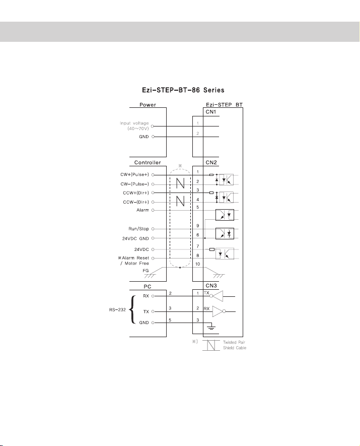
Fastech Ezi-Step BT-42 Series User manual

Operating Manual
www.fastech.co.kr

www.fastech.co.kr - 2
FASTECH Co.,Ltd.
●
●
●
●
●
●
●
●
●
●
●
●
●
●
●
●
●
●
●
●
●
●
●
●
●
●
●
●
●
●
●
●
●
●
●
●
●
●
●
●
●
●
●
●
●
●
●
●
●
●
●
●
●
●
●
●
●
●
●
●
●
●
●
●
●
●
●
●
●
●
●
●
●
●
●
●
●
●
●
●
●
●
●
●
●
●
●
●
●
●
●
●
●
●
●
●
●
●
●
●
●
●
●
●
●
●
●
●
●
●
●
●
●
●
●
●
●
●
●
●
●
●
●
●
●
●
●
●
●
●
●
●
●
●
●
●
●
●
●
●
●
●
●
●
●
●
●
●
●
●
●
●
●
●
●
●
●
●
●
●
●
●
●
●
●
●
●
●
●
●
●
●
●
●
●
●
●
●
●
●
●
●
●
●
●
●
●
●
●
●
●
●
●
●
●
●
●
●
●
●
●
●
●
●
●
●
●
●
●
●
●
●
●
●
●
●
●
●
●
●
●
●
●
●
●
●
●
●
●
●
●
●
●
●
●
●
●
●
●
●
●
●
●
●
●
●
●
●
●
●
●
●
●
●
●
●
●
●
●
●
●
●
●
●
●
●
●
●
●
●
●
●
●
●
●
●
●
●
●
●
●
●
●
●
●
●
●
●
●
●
●
●
●
●
●
●
●
●
●
●
●
●
●
●
●
●
●
●
●
●
●
●
●
●
●
●
●
●
●
●
●
●
●
●
●
●
●
●
●
●
●
●
●
●
●
●
●
●
●
●
●
●
●
●
●
●
●
●
●
●
●
●
●
●
●
●
●
●
●
●
●
●
●
●
●
●
●
●
●
●
●
●
●
●
●
●
●
●
●
●
●
●
●
●
●
●
●
●
●
●
●
●
●
●
●
●
●
●
●
●
●
●
●
●
●
●
●
●
●
●
●
●
●
●
●
●
●
●
●
●
●
●
●
●
●
●
●
●
●
●
●
●
●
●
●
●
●
●
●
●
●
●
●
●
●
●
●
●
●
●
●
●
●
●
●
●
●
●
●
●
●
●
●
●
●
●
●
●
●
●
●
●
●
●
●
●
●
●
●
●
●
●
●
●
●
●
●
●
●
●
●
●
●
●
●
●
●
●
●
●
●
●
●
●
●
●
●
●
●
●
●
●
●
●
●
●
●
●
●
●
●
●
●
●
●
●
●
●
●
●
●
●
●
●
●
●
●
●
●
●
●
●
●
●
●
●
●
●
●
●
●
●
●
●
●
●
●
●
●
●
●
●
●
●
●
●
●
●
●
●
●
●
●
●
●
●
●
●
●
●
●
●
●
●
●
●
●
●
●
●
●
●
●
●
●
●
●
●
●
●
●
●
●
●
●
●
●
●
●
●
●
●
●
●
●
●
●
●
●
●
●
●
●
●
●
●
●
●
●
●
●
●
●
●
●
●
●
●
●
●
●
●
1
5
7
7
8
8
9
10
11
12
12
12
14
14
15
16
16
17
17
17
18
18
18
18
19
19
19
20
20
21
21
22
23
23
23
Table of Contents
1. Precautions
2. Main Characteristics
3. Drive Specification and Dimension
3.1 Drive Specification
4. Motor Specification and Size
4.1 BT-42 Series
4.2 BT-56 Series
4.3 BT-86 Series
4.4 Motor Torque Characteristics
5. Installation and Cabling
5.1 Notes on Installation
5.2 Connection Diagram
6. Setting and Operating
6.1 Status monitor LED
6.2 Power Connection Connector(CN1)
6.
3
Signal Connection Connector(CN2)
6.4 Communication Connection Connector(CN3)
7. Setting Up Parameters
7.1 Setting Up Parameters
7.2 Resolution Selection
7.3 Stop Current Selection
7.4 Rotational Direction Selection
7.5 Pulse Input Selection
7.6 Alarm Reset Input Selection
7.7 Alarm Output Selection
7.8 RUN/STOP Output Selection
7.9 Motor Number, Motor Coils Current
8. System Configuration
8.1 Option
9. Control Signal Input/Output Description
9.1 Input signal
9.2 Output signal
Appendix
Cable for RS-232C
Connector

1 - www.fastech.co.kr
FASTECH Co.,Ltd.
※ Before operation ※
●
Thank you for your purchasing Ezi-STEP BT.
●
Ezi-STEP BT is an all-in-one Unit. For high-speed and high-precision drive of a stepping
motor, Ezi-STEP BT is an unique drive that adopts a new control scheme owing to an
on-board high-performance 32bit digital signal processor.
●
This manual describes handling, maintenance, repair, diagnosis and troubleshooting of Ezi-
STEP BT.
●
Before operating Ezi-STEP BT, thoroughly read this manual.
●
After reading the manual, keep the manual near the Ezi-STEP BT so that any user can read
the manual whenever needed.
1. Precautions
◆
General Precautions
●
Contents of this manual are subject to change without prior notice for functional improvement,
change of specifications or user's better understanding.
Thoroughly read the manual provided with the purchased Ezi-STEP BT.
●
When the manual is damaged or lost, please contact with Fastech's agents or our company
at the address on the last page of the manual.
●
Our company is not responsible for a product breakdown due to user's dismantling for the
product, and such a breakdown is not guaranteed by the warranty.
◆
Put the Safety First
●
Before installation, operation and repairing the Ezi-STEP BT, thoroughly read the manual and
fully understand the contents. Before operating the Ezi-STEP BT please, understand the
mechanical characteristics of the Ezi-STEP BT and related safety information and precautions.
●
This manual divides safety precautions into Attention and Warning.
If user does not properly handle the product, a dangerous
situation (such as an electric shock) may occur resulting in
deaths or serious injuries.
Warning
:
If user does not properly handle the product, the user may
seriously or slightly injured and damages may occur in the
machine.
Attention
:
●
Although precaution is only a Attention, a serious result could be caused depending on
the situation. Follow safety precautions.

www.fastech.co.kr - 2
FASTECH Co.,Ltd.
Check the Product is damaged or parts are missing.
Otherwise, the machine may get damaged or the user may get injured.
◆
Check the Product
Attention
Carefully move the Ezi-STEP BT.
Otherwise the Product may get damaged or User's foot may get injured
by dropping the product.
Use non-flammable materials such as metal in the place where the
Ezi-STEP BT is to be installed.
Otherwise, a fire may occur.
When installing several Ezi-STEP BT in a sealed place, install a
cooling fan to keep the ambient temperature of the Ezi-STEP BT as
50℃ or lower.
Otherwise, a fire or other kinds of accidents may occur due to
overheating.
The process of Installation, Connection, Operation, Checking and
Repairing should be done with qualified person.
Otherwise, a fire or other kinds of accidents may occur.
◆
Installation
Attention
Keep the rated range of lnput Voltage for Ezi-STEP BT.
Otherwise, a fire or other kinds of accidents may occur.
Cable connection should follow the wiring diagram.
Otherwise, a fire or other kinds of accidents may occur.
Before connecting cables, check if input power is off.
Otherwise, an electric shock or a fire may occur.
The case of the Ezi-STEP BT is insulated from the ground of the
internal circuit by the condenser. Ground the Ezi-STEP BT.
Otherwise, an electric shock or a fire may occur.
◆
Connect Cables
Warning
Attention
Warning

3 - www.fastech.co.kr
FASTECH Co.,Ltd.
Stop supplying power to the main circuit and wait for a while before
checking or repairing the Ezi-STEP BT.
Electricity remaining in the capacitor may cause danger.
Do not change cabling while power is being supplied.
Otherwise, the user may get injured or the product may get damaged.
Do not reconstruct the Ezi-STEP BT.
Otherwise, an electric shock may occur or the reconstructed product
can not get After-Service.
◆
Check and Repair
Warning
If a protection function(alarm) occurs, firstly remove its cause and
then release(alarm reset) the protection function.
If you are operating continuously without removing its cause, the
machine may get damaged or the user may get injured.
Do not make Motor Free and make input signal to ON during
operation.
Motor will stop and stop current will become zero. The machine may get
damaged or the user may get injured.
Make all input signals to OFF before supply input voltage to
Ezi-STEP BT.
The machine may get damaged or the user may get injured by motor
operation.
All parameter values are set by default factory setting value.
Change this value after reading this manual throughly.
Otherwise, the machine may get damaged or other kinds of accidents
may occur.
◆
Operation
Attention

www.fastech.co.kr - 4
FASTECH Co.,Ltd.
■
Combination List of Ezi-STEP BT
■
Part Numbering
Ezi-STEP-BT-42S-
□
Motor + Drive Unit Type
Drive Series Type
User Code
42 : 42mm
56 : 56mm
86 : 86mm
Motor Flange Size
S : Single
M : Middle
L : Large
XL: Extra Large
Motor Length
Unit Part Number
Ezi-STEP-BT-42S
Ezi-STEP-BT-42M
Ezi-STEP-BT-42L
Ezi-STEP-BT-42XL
Ezi-STEP-BT-56S
Ezi-STEP-BT-56M
Ezi-STEP-BT-56L
Ezi-STEP-BT-86M
Ezi-STEP-BT-86L
Ezi-STEP-BT-86XL

5 - www.fastech.co.kr
FASTECH Co.,Ltd.
Sensorless Stall Detection
1
High precision Microstep function and Filtering (Patent pending)
The high-performance DSP operates at step resolutions of 1.8°up to maximum 0.0072°(1/250
steps) and Ezi-STEP® adjusts PWM control signal in every 25μsec, which makes it possible for
more precise current control, resulting in high-precision Microstep operation.
Microstep and Filtering
2
2. Main characteristics
Software Damping
3
Detecting the loss-of-synchronization with
on-board DSP (Patent pending)
Ezi-STEP® can detect the loss-of-synchronization
of a stepping motor without the addition of an
external sensor. By monitoring the voltage, current,
and back-emf signal, the on-board DSP estimates
the current position of a rotor and enables it to
detect the loss-of-synchronization (an impossible
task for a conventional stepping motor drive), this
allows for high-speed operation at 100% torque
rating without loss-of-synchronization*.
*Effective only over 300rpm
Vibration suppression and high-speed op-
eration (Patent pending)
Vibration suppression and High-speed operation
(Patent pending) Motor vibration is created by
magnetic flux variations of the motor, lower current
from the drive due to back-emf from the motor at
high speeds and lowering of phase voltages from
the drive. Ezi-STEP® drive detects these problems
and the DSP adjusts the phase of the current
according to the pole position of the motor, drasti-
cally suppressing vibration. This allows the smooth
operation of the motor at high speed.

www.fastech.co.kr - 6
FASTECH Co.,Ltd.
Ezi-STEP® provides loss of step, run/stop, over-current, over-heat, over-voltage, power, and
motor connection alarms that can be monitored by the controller and visible by a motor-mounted
flashing led indicator.
Drive Output Signal Monitoring
4
Depending on the speed of a stepping motor, Ezi-STEP® automatically increases the supply volt-
age and prevents the torque lowering due to the low operating voltage to the motor caused by
back-emf voltage, this enables high-speed operation. Additionally, the software damping algorithm
minimizes the vibration and prevents the loss-of-synchronization at high-speed.
Improvement of High-Speed Driving
5

7 - www.fastech.co.kr
FASTECH Co.,Ltd.
Motor Model BT-42 Series BT-56 Series BT-86 Series
Input Voltage 24VDC ±10% 24VDC ±10% 40~70VDC
Control Method Bipolar PWM drive with 32bit DSP
Current
Consumption Max : 500mA (Except motor current)
Operating
Condition
Ambient
Temperature
In Use : 0~50℃
In Storage : -20~70℃
Humidity In Use : 35~85%RH (Non-Condensing)
In Storage : 10~90%RH (Non-Condensing)
Vib. Resist. 0.5G
Function
Resolution
(P/R)
500 1,000 1,600 2,000 3,200 3,600 4,000 5,000 6,400 8,000 10,000
20,000 25,000 36,000 40,000 50,000 (Set by RS-232C Communication)
*Default : 10,000
Max. Input Pulse
Frequency 500KHz (Duty 50%)
Protection
Functions
Over Current Error, Over Speed Error, Step Out Error, Over Temperature
Error, Over Regenerated Voltage Error, Motor Connect Error, Motor
Voltage Error, System Error, ROM Error, Input voltage Error
(Identifiable which alarm is activated by counting the blinking times of
status monitor LED)
LED Display Power Status(Green), Alarm Status(Red)
STOP Current 10%~100% (Set by RS-232C Communication) Be setted to set value of
STOP Current after 0.1 second after motor stop. *Default : 50%
Pulse Input
Method
1 Pulse/2 Pulse (Set by RS-232C Communication)
1 Pulse : Pulse/Direction, 2 Pulse : CW/CCW *Default : 2 Pulse
Rotational
Direction
CW/CCW (Set by RS-232C Communication)
Used when changing the direction of motor rotate. *Default : CW
Speed/Position
Control Command Pulse train input (Photocoupler Input)
I/O
Signal
Input Signal Motor Free/Alarm Reset (Photocoupler Input)
Output Signal Alarm, Run/Stop (Photocoupler Output)
3. Drive Specification and Dimension
3.1 Drive Specification

www.fastech.co.kr - 8
FASTECH Co.,Ltd.
M O D E L UNIT BT-42S BT-42M BT-42L BT-42XL
DRIVE METHOD ---- BI-POLAR BI-POLAR BI-POLAR BI-POLAR
NUMBER OF PHASES ---- 2 2 2 2
VOLTAGE VDC 3.36 4.32 4.56 7.2
CURRENT per PHASE A1.2 1.2 1.2 1.2
RESISTANCE per PHASE Ohm 2.8 3.6 3.8 6.0
INDUCTANCE per PHASE mH 2.5 7.2 8.0 15.6
HOLDING TORQUE N·m 0.32 0.44 0.5 0.65
ROTOR INERTIA g·㎠ 35 54 77 114
WEIGHTS g220 280 350 500
LENGTH (L) mm 33 39 47 59
ALLOWABLE
OVERHUNG LOAD
(DISTANCE FROM
END OF SHAFT)
3mm
N
22 22 22 22
8mm 26 26 26 26
13mm 33 33 33 33
18mm 46 46 46 46
ALLOWABLE THRUST LOAD NLower than motor weight
INSULATION RESISTANCE MOhm 100min. (at 500VDC)
INSULATION CLASS ---- CLASS B (130℃)
OPERATING TEMPERATURE ℃0 to 55
4. Motor specifications and Size
4.1 BT-42 Series
4.1.1 Motor Specifications
4.1.2 Motor Dimension (mm)

9 - www.fastech.co.kr
FASTECH Co.,Ltd.
M O D E L UNIT BT-56S BT-56M BT-56L
DRIVE METHOD ---- BI-POLAR BI-POLAR BI-POLAR
NUMBER OF PHASES ---- 2 2 2
VOLTAGE VDC 1.56 1.62 2.7
CURRENT per PHASE A 3 3 3
RESISTANCE per PHASE Ohm 0.52 0.54 0.9
INDUCTANCE per PHASE mH 1.0 2.0 3.8
HOLDING TORQUE N·m 0.64 1.0 1.5
ROTOR INERTIA g·㎠ 120 200 480
WEIGHTS g500 700 1150
LENGTH (L) mm 46 54 80
ALLOWABLE
OVERHUNG LOAD
(DISTANCE FROM
END OF SHAFT)
3mm
N
52 52 52
8mm 65 65 65
13mm 85 85 85
18mm 123 123 123
ALLOWABLE THRUST LOAD NLower than motor weight
INSULATION RESISTANCE MOhm 100min. (at 500VDC)
INSULATION CLASS ---- CLASS B (130℃)
OPERATING TEMPERATURE ℃0 to 55
4.2.2 Motor Dimension (mm)
4.2 BT-56 Series
4.2.1 Motor Specifications
*
* : There are 2 kinds size of front shaft diameter for BT-56 series as Φ6.35 and Φ8.0.

www.fastech.co.kr - 10
FASTECH Co.,Ltd.
4.3.2 Motor Dimension (mm)
4.3 BT-86 Series
4.3.1 Motor Specifications
M O D E L UNIT BT-86M BT-86L BT-86XL
DRIVE METHOD ---- BI-POLAR BI-POLAR BI-POLAR
NUMBER OF PHASES ---- 2 2 2
VOLTAGE VDC 2.4 3.6 4.38
CURRENT per PHASE A 6 6 6
RESISTANCE per PHASE Ohm 0.4 0.6 0.73
INDUCTANCE per PHASE mH 3.5 6.5 8.68
HOLDING TORQUE N·m 4.0 7.5 9.0
ROTOR INERTIA g·㎠ 1400 2700 4000
WEIGHTS Kg 2.3 3.8 5.3
LENGTH (L) mm 79 117 155
ALLOWABLE
OVERHUNG LOAD
(DISTANCE FROM
END OF SHAFT)
3mm
N
270 270 270
8mm 300 300 300
13mm 350 350 350
18mm 400 400 400
ALLOWABLE THRUST LOAD NLower than motor weight
INSULATION RESISTANCE MOhm 100min. (at 500VDC)
INSULATION CLASS ---- CLASS B (130℃)
OPERATING TEMPERATURE ℃0 to 55

11 - www.fastech.co.kr
FASTECH Co.,Ltd.
※Measured Condition
Motor Voltage = 24VDC
Motor Current = Rated Current(Refer to Motor Specification)
Drive = Ezi-STEP BT
※Measured Condition
Motor Voltage = 24VDC
Motor Current = Rated Current(Refer to Motor Specification)
Drive = Ezi-STEP BT
※Measured Condition
Motor Voltage = 70VDC
Motor Current = Rated Current(Refer to Motor Specification)
Drive = Ezi-STEP BT
4.4 Motor Torque Characteristics

www.fastech.co.kr - 12
FASTECH Co.,Ltd.
5.
Installation and Cabling
5.1 Notes on Installation
1) Ezi-STEP BT is designed for indoor use only.
2) The ambient temperature of the room should be 0
℃~50
℃.
3) If the temperature of the product case is higher than 50
℃, radiate heat of the
outside to cool down.
4) Do not install Ezi-STEP BT under direct rays, near magnetic or radioactive
objects.
5.2 Connection Diagram
*Alarm Rest signal line is also
used for Motor FREE signal.
(For details, please refer to
the section for Control Input/
Output signal)

13 - www.fastech.co.kr
FASTECH Co.,Ltd.
*Alarm Rest signal line is also
used for Motor FREE signal.
(For details, please refer to
the section for Control Input/
Output signal)

www.fastech.co.kr - 14
FASTECH Co.,Ltd.
6.
Setting and Operation
Statua Monitor LED
RS-232C Communication Connection
Connector(CN3)
Power Connection Connector(CN1)
Signal Connection
Connector(CN2)
6.1 Status Monitor LED
6.1.1 Status LED Function and Condition
indication Color Function Flash Condition
PWR Green Power Input Indication Lights when power is On
Flash when Motor Free status.
ALM Red Alarm Indication
Flash when protection function is activated
(Identifiable which protection mode is activated
by counting the LED flash times)

15 - www.fastech.co.kr
FASTECH Co.,Ltd.
Times Protection Conditions
1Over Current Error Excessive current flowed into a motor
2Over Speed Error Motor speed exceeded 3,000rpm
3Step Out Error Abnormally motor do not followed pulsed input
5Over Temperature Error Internal temperature of a motor drive exceeded 55℃
6Over Regenerative
Voltage Error
Back-EMF is more high limit value
BT-42/BT-56 Series : 50V, BT-86 Series : 70V
7Motor Connect Error Power is ON without connection of motor cable to drive
9Motor Voltage Error Motor voltage is less than low limit value
BT-42/BT-56 Series : 20V, BT-86 Series : 36V
11 System Error Error occurs in drive system
12 ROM Error Error occurs in Parameter storage Device(ROM)
14 Input Voltage Error Power source voltage is out of limited value
BT-42/BT-56 Series : 20~28V, BT-86 Series : 40~70V
6.1.2 Protection functions and LED flash times
Alarm LED flash
(ex: Step out)
6.2 Power Connection Connector(CN1)
NO. Function Pin Layout
1Input Power : +24VDC
2Input Power : GND
3F. GND
4NC
※Only for BT-42, BT-56 Series.
4
2
3
1
NO. Function Pin Layout
1Input Power : 40~70VDC
2Input Power : GND
※Only for BT-86 Series.
2 1

www.fastech.co.kr - 16
FASTECH Co.,Ltd.
6.3 Signal Connection Connector(CN2)
NO. Function Input/Output Pin Layout
1CW+(PULSE+) Input
2CW-(PULSE-) Input
3CCW+(DIR+) Input
4CCW-(DIR-) Input
5ALARM Output
6GND Input
7+24VDC Input
8ALARM RESET Input
9RUN/STOP Output
10 F. GND ----
6.4 Communication Connection Connector(CN3)
NO. Function Input/Output Pin Layout
1Tx Output
2Rx Input
3GND ---- 1 2 3
2
1
10
9

17 - www.fastech.co.kr
FASTECH Co.,Ltd.
7.1 Setting Up Parameters
RS-232C serial communication port of a computer is used to set up various parameters of
the motor drive. The set-up program is supplied with the product on a companion CD. It is
recommended to make a copy of the program in any folder on your computer. Then please
execute the program, named "Ezi-STEP BT Setting.exe", from the folder.
: Please select an appropriate Prot No. and press
button. Then it will display the various
parameter values previously stored in the drive.
: Display the parameter values stored in the drive.
※ Error Message
There is no response. (You may select wrong baudrate of wrong port
no.) : ① Select wrong Port No.
② Select already used Port No. in other program.
③ Communication cable is not connected.
④ Power is not supplied to drive.
7.2 Resolution Selection
Resolution means the number of pulses per one rotation of a motor.
Select a desired resolution by pressing in button on Ezi-STEP BT
Setting screen. The possible resolution values are 500~50,000.
Press button to save the value selected into the drive.
※ The default factory setting is 10,000[Pulses/Revolution].
: Save the parameter values displayed on the screen into the drive.
7. Setting Up Parameters

www.fastech.co.kr - 18
FASTECH Co.,Ltd.
7.3 Stop Current Selection
Stop Current means the motor current value automatically set in 0.1 sec after motor stops.
This is to prevent the overheat ot a motor when the motor is under long time idling. Select a
desired Stop Current by pressing in button on Ezi-STEP BT Setting
screen. The range of this value is 10~100 and the unit is a percentage.
7.5 Pulse Input Selection
As the Pulsed inputs, a user can choose One-pulse-mode(Pulse/Dir) or two-pulse-
mode(CW/CCW). Select a desired pulse mode by pressing in button
on Ezi-STEP BT Setting screen.
7.4 Rotational Direction Selection
The direction of the motor rotation can be selected either in CW(Clockwose) or in CCW(Count
er Clockwise). Select a desired rotation direction by pressing in
button on Ezi-STEP BT Setting screen.
Press button to save the value selected into the drive.
※ The default factory setting is 50%.
Press button to save the value selected into the drive.
※ The default factory setting is two pulse input mode(CW/CCW).
Press button to save the value selected into the drive.
※ The default factory setting is CW(Clockwise).
7.6 Alarm Reset Input Selection
Input method of Motor Free/Alarm Reset can be selected. Select a desired method by
pressing in button on Ezi-STEP BT Setting screen.
Press button to save the value selected into the drive.
※ The default factory setting is Nomal.
※ Caution : When you select 'Inverse' :
It can be 'Motor Free' status when power is applied to Ezi-STEP BT during Signal Connector(CN2) is not
connected. The power LED(green) is flash to show the status of 'Motor Free'
This manual suits for next models
12
Table of contents
Other Fastech Engine manuals
Popular Engine manuals by other brands

VBrick
VBrick dme Admin guide

MINN KOTA
MINN KOTA 1810244 quick start guide

Porsche
Porsche 944 Turbo 1988 Workshop manual

Hacker
Hacker A50-12L Glider instruction manual

SEW-Eurodrive
SEW-Eurodrive DFS Series operating instructions

Briggs & Stratton
Briggs & Stratton 120000 Operating & maintenance instructions