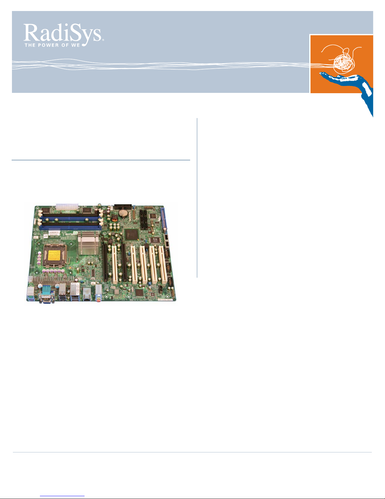
RadiSys Endura QZ35Q User manual

Procelerant™
Q35 ATX MOTHERBOARD
QUICK START GUIDE
Endura QZ35Q
This information is provided to help system designers quickly
configure, install, and operate a RadiSys QZ35Q ATX
motherboard. Refer to the Endura Q35 Motherboard Product
Manual for more detailed information.
Important precautions
WARNING!
When installing the motherboard into a chassis or
performing upgrades:
Always disconnect the power cord and plug before
assembling or upgrading. Parts on the motherboard can
remain powered even when the power supply is
switched off unless the power cord is disconnected.
Route wiring away from sharp edges, heat sources and
cooling fans.
Pay attention to the thermal requirements as stated in
the sections that follow. This motherboard requires
suitable airflow to maintain an ambient temperature
within the operating range.
When installing expansion cards, pay attention to the
maximum loads as stated. Use UL-approved peripheral
cards only.
There is a risk of explosion if the battery is replaced
with an incorrect type. Dispose of used batteries
according to the manufacturer's instructions. Refer to
the
Endura Q35 Motherboard Product Manual
for
further information.
Electrostatic discharge
WARNING!
This product contains static-sensitive components. Use
the electrostatic discharge (ESD) procedures described
at www.radisys.com/esd when you work with the
motherboard.
Wear a grounded wrist strap at a grounded work area
when you touch or come in contact with the
motherboard.
Keep the motherboard in its ESD shielding bag until a
step instructs you to remove it.
Failure to employ adequate anti-static measures can
cause irreparable damage to the motherboard and other
hardware components.
007-03196-0000 • December 2007
© 2007 by RadiSys Corporation. All rights reserved.
RadiSys is a registered trademark and Promentum is a trademark of RadiSys Corporation. All other trademarks, registered trademarks, service marks, and trade names are
the property of their respective owners.

Installation Guide
2
Quick Start
To install and operate your motherboard, do the following:
Install the motherboard into a suitable chassis.
Attach all necessary components and peripheral devices to the appropriate headers and
connectors on the board.
Power on the system.
Run the BIOS setup utility if you need to change any settings. To start the BIOS setup utility, press
the Delete key when prompted during system startup.
Attaching components and devices
See Figure 2, “Motherboard layout: top view” on page 3 for the location of components and
connectors on the motherboard. Refer to the Endura Q35 Motherboard Product Manual for further
information on interfaces and supported devices.
Attaching devices to the rear I/O panel
The I/O ports are color-coded in conformance with the PC 99 specification, and are designed to accept
standard cables. If necessary, refer to the product manual for the pin definitions of each connector.
Figure 1. Rear I/O panel
Video devices
The motherboard can be used with the following video devices:
1. VGA monitor, connected to the rear I/O panel VGA port
2. PCI Express x16 graphics cards1
3. Media expansion cards
1A second PCI Express x16 card can be used in the PCI Express x4 slot, but will have a reduced bandwidth.
PS/2 VGA
COM1 Serial
Mouse
Line Out
Line In
Keyboard Microphone
In
USB LAN 1
USB
LAN 2 Audio

Attaching components and devices
3
Figure 2. Motherboard layout: top view
KEYBOARD/
MOUSE
COM1
VGA
USB
2/3
4/5
LAN1
USB
0/1
LAN2
AUDIO
JPUSB1
FAN3
CPU
INTEL® Q35
EXPRESS CHIPSET
4-PIN
PWR FAN1:
CPU
FRONT
AUDIO
COM4 COM2COM3 USB11
USB 8/9 USB 6/7
IDE
JP2
FAN2
DIMM1A
DIMM2A
DIMM1B
DIMM2B
24-PIN
ATX POWER
SMBUS
PRINTER
BATTERY
INTEL®
ICH9
GPIO
JI2C1
JPL1
JPL2
JP5
JWD
JP3
SLOT1 PCI-33 MHZ
SLOT2 PCI-33 MHZ
SLOT3 PCI-33 MHZ
SLOT4 PCI-33 MHZ
SLOT6 PCI-33 MHZ
SLOT7 PCI-E x16
JRTC1
JI2C2
J9 I-SATA
0
1
2
3
4
5
FRONT PANEL
I/O HEADER
JPUSB2USB10
CD-IN
SLOT5 PCI-E x4

Installation Guide
4
Power supply
The QZ35Q ATX motherboard requires a 12V ATX power supply. Although most power supplies
generally meet the specifications required by the CPU, some are inadequate. Make sure that the power
supply you select can provide a 2-Amp current supply on a 5V standby rail.
It is strongly recommended that you use a high-quality power supply that meets 12V ATX power supply
specification 1.1 or above. It is also required that the 12V 4-pin power connection (J41) be used for
high-load configurations. In areas where power transmissions are present, you may choose to install a
line filter to shield the computer from noise. It is recommended that you also install a power surge
protector to help avoid problems caused by power surges.
Connecting the power supply
1. Ensure that the AC power cord is disconnected.
2. Attach the 24-pin main power supply connector to the 24-pin ATX power connector on the
motherboard (J40).
3. Insert the 4-pin power supply into the 4-pin ATX 12V connector (J41).
4. Connect the AC power cord.
Processor support
The motherboard supports the following Intel® embedded processors.
Intel Core™ 2 Duo E6400
Intel Core 2 Duo E4300
Intel Pentium® Dual-Core E2160
Intel Celeron® 440
If a processor you are interested in is not mentioned in this list, refer to the Procelerant Endura Q35
ATX Motherboard Tested Processors List on the RadiSys Web site for the latest information.
CPU and active heatsink Installation
Refer to the installation instructions accompanying the processor, or visit the Intel web site to view the
Boxed Intel® Processors in the 775-land Package - Integration Video.
If you purchase a CPU without active heatsink, make sure that you use only an Intel-certified, multi-
directional heatsink and fan.
WARNING!
Be careful not to bend the pins when installing or removing the CPU. This is a common cause of system
failure. To avoid bending the pins, handle the CPU with extreme care and insert it straight down into the
CPU socket. When removing the CPU, pull it straight up out of the socket.

Configuring BIOS settings
5
System memory
The motherboard provides four DIMM memory sockets. It supports up to 8 GB of unbuffered non-ECC
DDR2 677/800 MHz in 4 DIMMs. Refer to the Endura QZ35Q downloads page on the RadiSys Web
site for a list of tested memory modules for this motherboard.
Front panel I/O header
The front panel I/O header (JF1) is located by the edge of the motherboard, near the IDE and SATA
connectors. This header contains pins for various buttons and indicators that are typically on the front of
the chassis.
Jumpers
You may notice jumpers installed in various locations on the motherboard. The factory settings should
work for most applications, and will only need to be changed in rare circumstances. Refer to the
Procelerant Endura Q35 Motherboard Product Manual for further information.
Configuring BIOS settings
Most of BIOS configurations are handled by the BIOS setup utility, which stores configuration settings in
non-volatile flash memory.
It is a good idea to check the BIOS settings before installing the operating system to make sure the
default settings are appropriate for devices you have installed. To enter the BIOS setup utility, press the
Delete key during system startup. After installing the operating system, you may also want to change
the boot order in the BIOS, so that the hard disk is checked first.
If problems are encountered during system startup, error messages may be displayed on the monitor.
You may also want to use a diagnostic card that reads POST codes to determine where the system
encountered problems.
For further information, refer to the Procelerant Endura Q35 Motherboard Product Manual and BIOS
setup utility screen help.
PIN# Description PIN# Description Wiring Notes
16 Power LED 15 LED_Anode+ Connect pins 15 and 16 to the power LED
14 HDD LED 13 LED_Anode+ Connect pins 13 and 14 to the hard disk drive (HDD)
LED to display disk activity
12 NIC1 LED 11 LED_Anode+ Connect pins 11and 12 to the NIC1 LED to display
network activity
10 NIC2 LED 9 LED_Anode+ Connect pins 9 and 10 to the NIC2 LED to display
network activity
8 OH/Fan fail LED 7 LED_Anode+ Connect pins 7 and 8 to the overheat/fan failure LED
6 — 5 — Not connected
4 Ground 3 Reset button Connect pins 3 and 4 to the hardware reset button
2 Ground 1 Power button Connect pins 1 and 2 to the power button
1516
12

Installation Guide
6
Installing the operating system and device drivers
This motherboard has been tested with the following operating systems. Note that some devices
drivers may not yet be available.
Microsoft® Windows Vista® Premium
Microsoft Windows® XP Professional, SP2
Windows XP Embedded, SP2
Red Hat® Enterprise Linux® 4.0 AS
Novell® SUSE® Linux Professional 10.0
Knoppix Linux 5.0.1
Sun™ Solaris™ 10 Update 4
1. Install the operating system using a bootable CD-ROM. Follow the installation instructions provided
with the operating system.
2. Download the drivers for the required operating system from the RadiSys Web site. These are
available on the downloads page for the Q35 motherboard. For detailed instructions on installing
each driver, refer to the Procelerant Endura Q35 Motherboard Driver Installation Guide.
Where to get more product information
For additional product information, visit the motherboard product pages on the RadiSys Web site at
www.radisys.com for access to datasheets, product documentation, BIOS releases, and drivers.
Table of contents
Other RadiSys Motherboard manuals

RadiSys
RadiSys PROCELERANT SB5520DT1-SATA User manual

RadiSys
RadiSys ENDURA TP945GM User manual

RadiSys
RadiSys EPC-3208 Series User manual

RadiSys
RadiSys Endura GL815E User manual

RadiSys
RadiSys BG845G User manual

RadiSys
RadiSys PL35Q User manual

RadiSys
RadiSys KP915GV User manual

RadiSys
RadiSys P3000BX2 Series Reference guide