FATEK FBs-1HLC Installation manual

1
FBs-1HLC
Precision Load Cell Module
Operation manual
V1.1 06/07/2017
FATEK AUTOMATION CORP.
FATEK

2
Contents
Chapter 1 1HLC module introduction.......................................................................................................... 3
1.1
Module specification............................................................................................................................. 3
1.2
Module appearance and description.................................................................................................. 4
1.3
Application connections........................................................................................................................ 4
1.4
Communication interface between 1HLC and PLC:........................................................................ 6
1.5
1HLC application interface................................................................................................................... 6
1.5.1 Application interface contents and Modbus comparison table....................................................................6
1.5.2 Detailed description...........................................................................................................................................7
Chapter 2 Application examples.................................................................................................................. 8
2.1
Application connections........................................................................................................................ 8
2.2
Setting PLC communication parameters........................................................................................... 8
2.3
Ladder diagram programming............................................................................................................. 9
2.4
1HLC module calibration.................................................................................................................... 10
2.4.1 Zero-point calibration.......................................................................................................................................10
2.4.2 Full-span calibration.........................................................................................................................................10
2.4.3 Weight measuring............................................................................................................................................10

3
Chapter 1 1HLC module introduction
A load cell is formed by attaching a stress strain gauge to a metal elastic body. When the metal elastic
body is subjected to pressure or tensile force, the deformation of the elastic body is detected and
converted to an output voltage signal. PLC acquires data from 1HLC via the Modbus communication
protocol.
1.1
Module specification:
General specification
Supply voltage
DC 24V
Weight
127g
Operation temperature
-10°C to + 40°C (+14°F to + 104°F)
Operation humidity
85% relative humidity (non-condensing state)
Dimensions
90 (L) x 40 (W) x 80 (H) mm
Input signal and A/D conversion
A/D conversion method
24Bits △ Σ
A/D conversion speed
100 times/sec
Load cell excitation power
supply
DC 5V 5% , 120mA (for 8 350Ω load cells )
Max. measured voltage
-1mV ~ 39mV
Input sensitivity/resolution
Above 0.15V/D 1 / 60000 d
Digital
Status indicators
POWER、MD、ZERO、NET、GROSS
Memory
Calibration parameters and function settings are all saved to EEPROM
Features
1. Industrial-grade weight control design suitable for all kinds of extreme industrial environments
2. High noise-interference resistance; effectively suppresses interferences from power supplies,
electromagnetic waves, and wireless RF.
3. Small volume and occupies little space; convenient for storage in control stations, high precision,
and superior performances
4. Adjustable digital filtering may effectively suppress vibrations generated in local environment
5. Flexible calibration schemes and automatic stability detection
6. Automatic zero-point tracking for effective suppressing of zero-point drift occurring in load cells

4
1.2
Module appearance and description
Expansion flat
cable connector
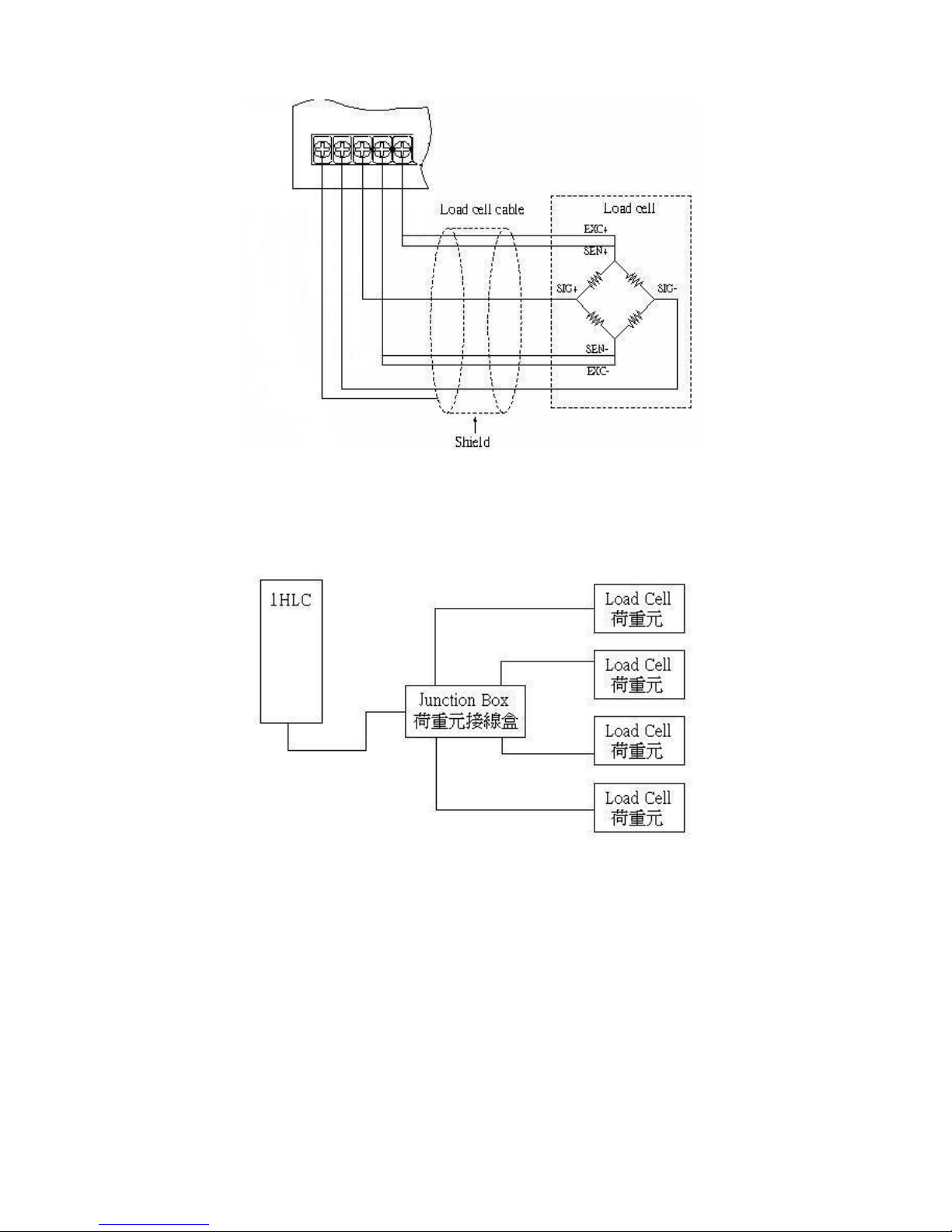
1.3
Application connections
Four-line connection
EXC: Load cell excitation power supply
(DC 5V 5%)
24V power supply
Status flag indicator
NET: net weight indicator
GRS: gross weight indicator
MD: stable indicator
ZRO: zero-point indicator
PORT4
PORT3
NETGRS MD ZRO
POW
SIG: signal source
SIG
+
SIG
-
EXC
+
EXC
-
FG FG FG
FG
FBs-1HLC
Expansion port cover
Port3 connect to PLC
Port4 connect to expanded CMXXE module
(CMXXE module can only use port 4)
5
Six-line connection
Multiple-load-cell connection
6
IN (X )
POW
RUN
ERR
TX RX
POW
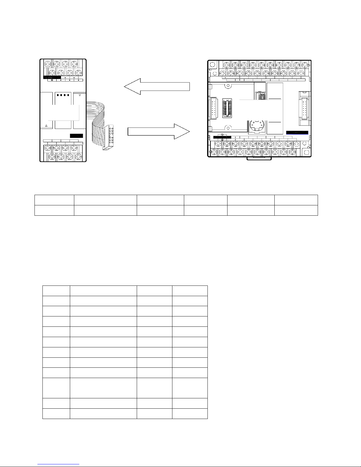
1.4
Communication interface between 1HLC and PLC:
PLC acquires data from 1HLC via the Modbus communication protocol.
max.
40 0mA
24V OUT
S/S
X0 X2
X1
X4 X6
X3 X5 X7
X8 X10
X9
X12
X11 X13
PORT4
NET GRS MD ZRO
PORT3
Fun150
0 I 2 3
4 5 6 7
8 9 I0 II
I2 I3
Slave Modbus Protocol Master
OUT( Y )
FBs-1HLC
IN AC100~240V
Y1 Y2
0 I 2 3
4 5 6 7
8 9
Y4 Y5 Y6
FBs-24MCR2-AC
Y8
SIG
+
SIG
-
EXC
+
EXC
-
C0 Y0 C2 Y3 C4 C6 Y7 Y9
FG FG FG FG
Connect to PLC using Winproladder and change the PORT 3 communication parameters of
Winproladder. The communication parameters of 1HLC are fixed as follow:
1.5
1HLC application interface:
1.5.1 Application interface contents and Modbus comparison table
Status/Control bit
Address
Name
Length
R/W
000002
Overload flag
Bit
R
000005
Display gross weight flag
Bit
R
000006
Display net weight flag
Bit
R
000007
Zero-point flag
Bit
R
000008
Unstable flag
Bit
R
000257
Adjust to zero
Bit
W
000258
Deduction
Bit
W
000263
Clear deduction
Bit
W
000513
Zero-point calibration
input
Bit
W
000514
Full-span calibration input
Bit
W
000773
Save EEP
Bit
W
PORT
Connection speed
Parity bit
Data bit
Stop bit
format
Port3
19200
No
8
1
RTU

7
Status/Settings register
Address
Name
Settings
Length
R/W
402305
AD internal value
Word
R
402307
Display value
2Word
R
402567
SPAN calibration
weight
2Word
R
402561
Max. weight
2Word
R/W
401793
Calibration error
message
0~3
Word
R/W
402049
AD sampling frequency
0=100、1=50、2=25、3=12.5、4=6.25Hz
Word
R/W
402052
Min. scale
1,2,5,10,20,50
Word
R/W
1.5.2 Detailed description
Status/Control bit
Address
Name
Description
000002
Overload flag
Flag ON when the measured weight is higher than the max. weight
000005
Display gross
weight flag
Displayed measurement value includes package weight
000006
Display net weight
flag
Displayed measurement value is actual weight
000007
Zero-point flag
Gross weight is 0 when=1
000008
Unstable flag
Conditions of unstable tracking time and unstable tracking area may be set for the
devices maintaining stable values
000257
Adjust to zero
Function to set or adjust the displayed value to zero when there is no load
when=1
000258
Deduction
Deduce the package weight of the load on the tray when=1
000263
Clear deduction
Clear the package weight deduction and display gross weight when=1
000513
Zero-point
calibration input
Zero-point button to be set during calibration when=1
000514
Full-span calibration
input
SPAN weight button to be set during calibration when=1 (SPANcalibration weight
should be set first)
000773
Save EEP
Save settings in EEPROM and automatically read previously saved settings at
power-on when=1

8
Status/Settings register
Address
Name
Description
402305
AD internal value
Value of scale analog signal voltage converted for internal calculations of the
scale.
402307
Display value
Actual measured weight after specification calibration and weight calibration.
402567
SPAN calibration
weight
Weight of known standardized weight in calibration.
402561
Max. weight
Set maximum weight of scale and display overload flag if exceeding the max.
weight.
401793
Calibration error
message
0 : normal
1
: AD abnormal
2
: weight calibration earlier than prerequisite calibration (e.g., SPAN1<ZERO)
3 : weight calibration precision higher than 0.1uV/D
Chapter 2 Application examples
2.1
Application connections
Complete the hardware wiring connection first; please refer to the hardware equipment and
connection scheme in below.
Hardware: FBs-24MC*1, FBs-1HLC*1, and scale*1
1.
Connect 1HLC cable to the left (communication) expansion port ofPLC.
2.
The 4 lines of the scale are connected to EXC+, EXC-, SIG+, and SIG- of 1HLC.
24V power supply
1HLC
24MC

9
2.2
Setting PLC communication parameters
Connect to PLC using Winproladder (24MC in this example) and change the PORT 3 communication
parameters of Winproladder. The communication parameters of 1HLC are fixed as follow:
PORT
Connection
speed
Parity bit
Data bit
Stop bit
format
Port3
19200
No
8
1
RTU
2.3
Ladder diagram programming
1. Establish FUN150 in the ladder diagram of Winproladder and use FUN150 Modbus to transmit data
from 1HLC.
Use X0 to control M102 and X1 to control M103 because M102 is the zero-point calibration control
coil (000513) and M103 is the full-span calibration control coil (000514) from the Modbus Master
table in step 2.
2. Register addresses to be read or written are set in the Modbus Master table; for the register
addresses of the slave please refer to 【1.5.1 Application interface contents and Modbus
comparison table】.

10
2.4
1HLC module calibration
Module calibration allows the subsequently measured values to be more precise. The registers and
connections in the calibration steps have already been converted by step 2 【Modbus Master Table】
in section 2.3 and the detailed corresponding registers are described in this section.
2.4.1
Zero-point calibration
Confirm that the tray or tank scale is empty and execute zero-point calibration input (X0 from 0 to 1); if
successful, the display value register DR500 (Modbus register 402307) will be zero. If not, confirm
whether the zero-point calibration operation is correct. Subsequently, set the status of X0 of zero-point
calibration back to 0 or else the display value will remain at 0 when measuring.
2.4.2
Full-span calibration
Place object of known weight (standardized weight) on the tray or tank scale and input the weight of
the object of known weight to the SPAN calibration weight register DR504 (Modbus register 402567);
after the displayed value is stable, execute SPAN calibration input (X1 from 0 to 1). The display value
register DR500 (Modbus register 402307) will be the same as DR504 (Modbus register 402567).
Subsequently, set X1 from 1 to 0 and remove the object of known weight (standardized weight);
measurements of objects may then begin.
Note: if register DR504 (Modbus register 402567) is zero then the display value register DR500
(Modbus register 402307) will remain zero when measuring weights.
2.4.3
Weight measuring
Place object on the tray and the display value register DR500 (Modbus register 402307) will display
the weight of the object according to the standard of the known weight in full-span calibration.
Table of contents
Other FATEK Control Unit manuals


Popular Control Unit manuals by other brands


Eizo
Eizo JC-100 user manual

Wireless Solution
Wireless Solution W-DMX G5 How to install

Pickering
Pickering PXI 40-795-001 user manual

acorn controls
acorn controls TEMPFLOW TZV Installation, operation and maintenance instructions

Bardiani
Bardiani BBZS5 Operating and maintenance instructions

GF
GF JRG 5195.025 Installation and operation instructions

GEM
GEM B52 operating instructions

Allen-Bradley
Allen-Bradley CAB6-HA 2 installation instructions

Ducati
Ducati CTR32 instruction manual

Vanderbilt
Vanderbilt ACTpro IOM Installation and configuration instructions

Nibco
Nibco T-103-HC Installation and maintenance guide

Siemens
Siemens RMH760B installation instructions