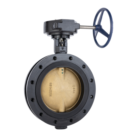
Nibco T-103-HC Product manual

INSTALLATION, OPERATION & MAINTENANCE INSTRUCTIONS
CAUTION: Only qualified personnel should undertake the procedures outlined in this document.
NIBCO INC., its agents, representatives and employees assumes no liability for the use of these
procedures. These procedures are offered as suggestions only.
NIBCO Technical Services • Phone: 1.888.446.4226 • Fax: 1.888.336.4226 1
NIBCO INC.
WORLD HEADQUARTERS
1516 MIDDLEBURY ST.
ELKHART, IN 46516-4740
USA
PHONE: 574.295.3000
FAX: 574.295.3307
WEB: www.nibco.com
Review Date: 01/18/2012
Original Date: NA
Installation and Maintenance Guidelines for
NIBCO®Bronze Gate Valves
1/4” to 3” Class 125, 150, 200, 300 and 175 WWP
Figure Numbers
T-103-HC
T-104-O
T-111-113
S-111-113
T-134-136
S-134-136
T-131
T-133
T-135
T-154-A
T-174-A
T-176-A
T-174-SS
T-176-SS

NIBCO Technical Services • Phone: 1.888.446.4226 • Fax: 1.888.336.4226 2
1.0 GENERAL INFORMATION
1.1 SCOPE
These instructions are furnished for use in the installation, operation and maintenance of
NIBCO 1/4” to 3” Class 125, 150, 200, 300 and 175 WWP bronze gate valves, with
screwed in or union bonnet, rising stem or non-rising stem, and having handwheel
operation.
1.2 GENERAL DATA
A. MANUFACTURER
NIBCO INC.
1516 Middlebury Street
Elkhart, IN 46516
Phone: (574) 295-3000
B. FIGURE NUMBERS AND DESCRIPTIONS
Figure Description
Number (Gate Valves)
T-111 Class 125 threaded end, rising stem valve, screw in bonnet
S-111 Class 125 solder end, rising stem, screw in bonnet
T-113 Class 125 threaded end, non-rising stem, screw in bonnet
S-113 Class 125 solder end, non-rising stem, screw in bonnet
T-131 Class 150 threaded end, rising stem, screw in bonnet
T-134 Class 150 threaded end, rising stem, union bonnet
S-134 Class 150 solder end, rising stem, union bonnet
T-135 Class 150 threaded end, rising stem, union bonnet, split wedge
T-136 Class 150 threaded end, non-rising stem, union bonnet
S-136 Class 150 solder end, non-rising stem, union bonnet
T-174-A Class 300 threaded end, rising stem, union bonnet, Ni-Alloy
wedge
T-176-A Class 300 threaded end, non-rising stem, union bonnet, Ni-Alloy
wedge
T-174-SS Class 300 threaded end, rising stem, stainless steel seat rings,
union bonnet
T-176-SS Class 300 threaded end, non-rising stem, stainless steel seat
rings, union bonnet
T-103-HC 175 WWP threaded end, non-rising stem, hose cap and chain
T-104-O 175 WWP threaded end, OS&Y solid wedge
All threaded end preparations of valves meet American National Pipe Thread
(N.P.T.) requirements.
All solder end valves meet the requirements of ANSI Standard B16.22.

NIBCO Technical Services • Phone: 1.888.446.4226 • Fax: 1.888.336.4226 3
C. IDENTIFICATION PLATES
An aluminum identification plate is attached beneath the handwheel nut. This
identification plate gives the figure number of the valve, some general information
about the trim and location of NIBCO’s corporate offices.
When more detailed information is required, the NIBCO Bronze & Iron or Fire
Protection catalog should be referred to using the valve figure number as the
guide.
D. SERVICE
When installing valves for service in corrosive media, the NIBCO Chemical
Resistance Guide may be consulted for specific data or contact can be made
with NIBCO Technical Services. It is, however, the obligation of the user to make
the ultimate decision of fitness for use.
E. PRESSURE TEMPERATURE RATINGS
Pressure and temperature ratings may be found in the Engineering section of the
latest printing of NIBCO Bronze & Iron or Fire Protection Catalogs. This
information is taken from applicable ANSI or UL/FMRC Standards.
F. CODES & REGULATIONS
A valve used under the jurisdiction of the ASME boiler and pressure vessel code,
the ANSI code for pressure piping, government or other regulations, is subject to
any limitation of that code or regulation and to the applicable ANSI Standard.
G. PRODUCTION TEST PROCEDURES
Valves are pneumatically shell tested and seat tested at a pressure of 80 psi in
accordance with Federal Specifications and MSS SP-80 Manufacturers
Standardization Society Requirements.
Fire Protection valves are tested in accordance with the appropriate Underwriters
Laboratories (UL) and Factory Mutual Research Corp. (FMRC) specifications.
H. PRINCIPAL DIMENSIONS
Principal dimensions of the valve are specified in the appropriate catalog.
1.3 DETAILED DESCRIPTION
The gate valves listed above and covered in these instructions are bronze valves made
of ASTM B62 material for Class 125, 150, and 175 WWP valves and from ASTM B61
material for Class 200 and 300 valves.
The valves are operated with the handwheel and are used to start or stop the flow of
fluids in piping systems. Clockwise rotation of the handwheel closes the valve.

NIBCO Technical Services • Phone: 1.888.446.4226 • Fax: 1.888.336.4226 4
The body and bonnet are held together by threads of the male and female type; male
threads being on the bonnet section and female threads being within the body. There
are no gaskets between the body and bonnet to affect seals. This is strictly a metal-to-
metal seal as required by standards. This general arrangement is used on the Class 125
and is also used on the Class 150 gate valves.
For the union bonnet arrangement the body has male threads, the bonnet has no
threads at all, however, a threaded union nut is placed over the bonnet to fasten it to the
body. The seal between the body and bonnet is also metal-to-metal without a gasket.
Flow through the valve is stopped by forcing the wedge down between the seats of the
body. The wedge is a solid type and is guided through its entire travel by guides in the
body.
The head of the stem on the rising stem version fits into a T-slot in the top of the wedge
to allow sufficient wedge movement for effective seating with the seats of the body. On
the non-rising stem version, the wedge has internal female threads and the stem has
male threads which are left handed to cause the wedge to close when the handwheel is
turned in a clockwise direction and the wedge to rise when it is turned in a
counterclockwise direction.
All valves have back seats between the shoulder of the stem and the valve bonnet. This
is a requirement of standards so that the valve may be repacked while the valve is under
full pressure. CAUTION: This is dangerous and could result in serious injury. It is
not recommended by NIBCO. In addition, standards, organizations, and governing
societies today do not encourage valves to be repacked while the valve is transmitting a
fluid at full pressure and/or temperature.
The stuffing box is formed by the annular space between the stem and the bonnet and is
filled with non-asbestos packing. The packing is compressed in the stuffing box by a
gland bushing and the packing nut drawn down against the packing by turning the nut
clockwise.
2.0 INSTALLATION
2.1 PRELIMINARY INFORMATION
The gate valves should preferably be installed with the stem pointed vertically upward.
However, it is normally acceptable to have the valve stem pointed in a horizontal position
either in vertical or horizontal piping.
Although a gate valve will function satisfactorily in an inverted position it is not generally
recommended because it allows fluids to become trapped in the bonnet cavity resulting
in contamination and inability to fully drain the system. This is critical in water lines
exposed to freezing temperatures.
Valves are shipped in the closed position to prevent damage to the seating surfaces.
There is not internal blocking used for shipment. All NIBCO valves are shipped in
cardboard boxes for protection against exterior damage and accumulation of dust or dirt

NIBCO Technical Services • Phone: 1.888.446.4226 • Fax: 1.888.336.4226 5
on the delicate seating surfaces. The boxes are not waterproof and, therefore, require
that they be protected from the weather.
2.2 HANDLING AND INSTALLATION
Each valve should be handled very carefully and not dropped or thrown into a dirty
environment before it is assembled into the system. Under no circumstances should the
valve be installed into the line by wrenching through the valve body, this means that
when a valve is being threaded onto a pipe, the wrench should be on the end where the
joint is being made.
It is very important to make certain that the threads of the pipe are clean at all times and
machined properly. When improperly tapered pipe is screwed into the female valve
threads the pipe can be screwed so deep that it can ruin the seats of the valve. Care
should also be used to assure that the valve is not over tightened because the steel pipe
is much stronger than the bronze material, therefore, the bronze will distort and cause
valve malfunction or leakage at the joint. When screwing the valve onto the pipe, the
wedge should remain in the closed position.
On solder end type valves it is necessary to make sure that the valve wedge is in the
open position while it is being heated for soldering into the line. The major caution here
is that the valve not be overheated and. that the proper amount of solder is used so that
it does not flow into the valve rendering it inoperable.
Attached to this report in the Appendix are proper instructions for soldering, brazing, and
threading type installation of valves.
In the event that it is necessary to remove the bonnet before the valve is put into a line
either for brazing, soldering or threading in, it is always essential that the bonnet be
removed with great care. It is necessary that a chain wrench rather than a pipe wrench
be used to loosen the bonnet union nut. If at all possible, it is more desirable to use a
socket wrench to remove the nut. The union nut, body and bonnet should all be marked
so they can be returned to the same position as originally assembled. After the nut has
been carefully removed or in the case of a screw in bonnet, the bonnet has been broken
loose, (which may require slight impact), it is then necessary to open the wedge
approximately to its halfway position before removing the bonnet assembly from the
valve body. After doing this, it is important that a mark be put on the wedge and the body
so that it is put back in the same position in the valve body, as it was taken out.
It is vital that no nicks or scars be put 'on the body or bonnet sealing areas, as this will
create a leak path. It is extremely important to make sure that the wedge does not fall
and hit any hard surface as it is being removed from the valve. Any mark or dent may
cause leakage on the delicate seating surfaces after the valve is reassembled.
The valve body should then be installed into the pipe system using the appropriate
procedures as outlined in valve installation for soldered, brazed or threaded ends. When
reassembling the valve the wedge should be again positioned at the approximate
halfway open position. Care should also be exercised so the wedge guides are properly
engaged in the body guides.
A slight amount of lubricant equivalent to about 10 weight oil should be put on the
bonnet joint sealing surface of the body and the bonnet and on the top side of the bonnet

NIBCO Technical Services • Phone: 1.888.446.4226 • Fax: 1.888.336.4226 6
when union nut joints are used. This gives lubrication to the joint so good tightening
pressures can be applied. The chain wrench or socket wrench should be used to tighten
the bonnet. Stop the union nut approximately at the same place where it was when the
valve was disassembled or possibly slightly past that mark. Remember any nick on the
surfaces on the bonnet sealing area assures leakage.

After the valve has been installed, the valve should be tested to make sure that it opens
and closes easily and that the bonnet joints or pipe joints are not leaking.

3.0 OPERATION
Gate valves should never be used for throttling purposes. They should be fully opened
or fully closed. If the valves were only slightly opened, wire drawing an erosion of the
wedge and seats would result. It is not recommended valves be tightly back-seated as
line contamination over a long period of time may lock up the valve causing problems
when the valve has to be closed.
4.0 TROUBLESHOOTING
4.1 LEAKAGE THROUGH THE STUFFING BOX
Leakage through the stuffing box packing may be stopped by tightening the packing nut. Do not
over tighten as excessive tightening may cause difficult operation of the valve and could cause
damage to the stem or packing nut.
If the gland has run out of travel, isolate and depressurize the valve for repacking or the addition
of more packing. Repacking of valves under pressure is not a recommended practice. This is
dangerous and could result in serious injury even if the valve appears to be back-seated.
Foreign matter may have accumulated on the back seat, or by accident the stem could be
knocked off the back seat position thereby allowing dangerous fluids to injure maintenance
personnel.
Remove the handwheel packing nut and gland to remove the old packing. After the packing is
removed, discard and do not try to put it back once it has been removed. Clean the stem and
examine it for damage. On very small valves the packing is sometimes rope and is sometimes
spiral wound around the stem and pushed into the stuffing box. Install the new packing which
may be one piece or split rings. If it is split ring rope packing install one ring at a time with the
diagonal cut in each ring being staggered 90° away from the cut in the ring below. Each ring
should be fully compressed in the stuffing box after it is placed in position before the next ring is
added.
Install the gland bushing and packing nut and tighten down. The packing nut should be
tightened only enough to prevent leakage. Pressurize the valve and check the packing for
leakage. Tighten as required.

NIBCO Technical Services • Phone: 1.888.446.4226 • Fax: 1.888.336.4226 7
5.0 MAINTENANCE
5.1 TOOLS AND EQUIPMENT
Standard wrenches and tools are suitable for servicing valves as follows:
A. For removing bonnet of the union type – a chain wrench is normally used or the
appropriate socket that will fit the bonnet union nut. For screw in type bonnets –
generally a socket wrench or open end wrench may be used if extreme caution is
used. Pipe wrenches on union nuts or screw in bonnets have a definite crushing
action which will deform the component and are not recommended.
A Standard packing tool can be used and/or a blunt hook is generally used to
remove packing rings. A screwdriver can be used to raise the packing gland (if it is in
the fully down position) and generally open end wrenches are used to tighten the
packing nut.
DOES NOT APPLY TO FIRE PROTECTION VALVES.
For any technical enquiries please call NIBCO Technical Services.
This manual suits for next models
13
Table of contents
Other Nibco Control Unit manuals

Nibco
Nibco LD2000 Series Assembly instructions

Nibco
Nibco T-413-B Product manual

Nibco
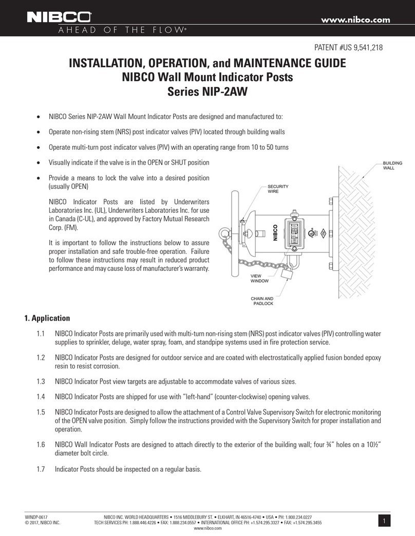
Nibco NIP-2AW series Manual

Nibco
Nibco Pressystem User manual

Nibco
Nibco LD-1000 Series Product manual

Nibco
Nibco LD-7000 Series Guide

Nibco
Nibco Webstone Series User manual

Nibco
Nibco Webstone Pro-Connect ProPush Series User manual