FATEK P5102S User manual

Thank you for purchasing FATEK HMI. Before installing or operating the unit, please
read this installation guide carefully to ensure correct use.
1. Safety Precautions
(Read these precautions before use.)
1.1 General
zUnpack and check the delivery for transportation damage. If any damage o
r
deformation is found, please notify the supplier.
zThe supplier is not responsible for the disassembled, altered or modified
device.
zNever allow fluid or any conductive particles to enter into the HMI.
Otherwise, it may damage the HMI, cause fire or malfunction.
zOnly qualified personnel may install the HMI, perform maintenance and
inspection.
zThe liquid crystal inside the LCD panel is a hazardous substance. If the
panel is damaged, avoid contact with the leaked liquid crystal. If the liquid
crystal spills on clothing or skin, use soap and wash off thoroughly. In case
of eye contact the liquid, hold the eye open, flush with plenty water and get
medical attention as soon as possible.
zDo not touch any terminals while the power is on. Otherwise, it may cause
injury due to electrical shock.
zDisconnect the power supply before installing the HMI, do wiring operation,
perform maintenance or inspection. Otherwise, it may cause damage o
r
electrical shock.
1.2 Installation
zThe installation may be carried out by qualified personnel only.
zInstall the HMI according to the installation procedures.
zCheck the power source voltage is within the specified range and the
polarity is correct before connecting the HMI.
zKeep signal and power supply cables away from high-voltage, large-current
carrying cables.
P5102S/N/N1 HMI Installation Guide
1
R

Caution
Make sure the HMI is properly grounded to prevent electrical
shock, fire or malfunction.
zHMI unit and other equipment should have the same electrical grounding
(reference voltage level), otherwise communication errors may occur.
1.3 Operation
z
Do not use sharp objects or excessive force to press the touch screen. This
may damage the touch screen. HMSP102 screen protector can be applied
to the HMI screen to protect it from damage, for ordering information, please
contact our sales department.
zDo not use the output signal of the device as any safety function or system
emergency stop. It may result in personal injury or equipment damage if a
malfunction of the touch occurs.
1.4 Maintenance and Service
zThe agreed guarantee applies.
zOnly qualified personnel should make repairs and perform maintenance.
zDisconnect the device from the power supply before carrying out cleaning or
maintenance.
zClean the front panel with a soft cloth and mild detergent.
z
Please use original replacement spare parts or accessories.
HMI
unit Other
equipment
HMI
unit
Other
equipment
GOOD BAD
Recommended Prohibited
DC24V
+
FG
DC24V
+
FG
No Connected
2

2. Part Names
and Dimensions
① Power Indicator
Light
② Mounting Hole
③ HB1 PLC
Connector
④ COM3/COM4
Termination
Switch
⑤ HB1 PLC Screw
Hole
⑥ Power Connector
⑦ COM3/COM4:
Pluggable
Terminal Block
⑧ Ethernet RJ45
Connector
(for N/N1 model)
⑨ Mini USB
Connector
⑩ USB Connector
⑪ COM1: DB-9 Male
Connector
⑫ Micro-SD Card
Slot
(for N1 model)
⑬ Audio Phone Jack
(for N1 model)
W 271.5 mm
H 213.5 mm
D
44.6
mm
1
2
34 5
678 9 10 11 12 13
W
H
D
3

3. Specifications
Model P5102S P5102N P5102N1
UL 61010-1
Technical
Consideraon
Type of item tested Control
Product Descripon Operator Panel
Connecons to mains
supply Permanent
Overvoltage category II
Polluon degree 2
Means of Protecon Class III
Environmental condions Operang Temp. 0~50°C
Storage Temp. -20~60
°C
For use in wet locaons No
Equipment mobility Built in
Operang condions Continuous
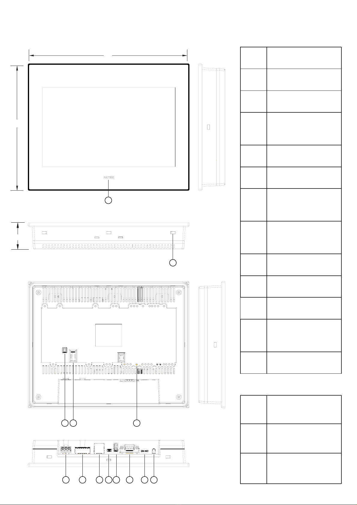
Overall size 271.5 x 213.5 x 44.6 (mm)
Weight 1340 (g) 1360 (g) 1380 (g)
Marked degree of
protecon
Front panel: IP65 / Rear Case: IP20 to IEC 60529
Type 1 to UL 50E
Equipment classificaon Industrial, Professional, Commercial
Equipment class Class III
Equipment type Permanently connected, Fixed
I/O Port
Serial 1 Connector: D-Sub 9-Pin
COM1:
RS-232
(TXD, RXD, RTS, CTS)
Serial 2
Connector: Pluggable Terminal Block
COM3: RS-422/485 (Isolaon)
COM4: RS-485 (Isolaon)
LAN --- 10M/100M 10M/100M
USB USB2.0 Type-A (Host)x1
USB2.0 Type mini-B (Device)x1
Micro SD --- --- Yes
Audio --- --- Yes
PLC Extension HB1 main units + B1 extension modules
Terminaon
Switch Yes (For RS-422/485)
Power
Power Input 24VDC±20% (Isolated Power)
Consumpon 420mA@24VDC
Insulaon 50MΩat 500VDC
Environment
Relave Humidity 10%~90%@ 40°C (non-condensing)
Withstand Voltage AC500V/20mA/1 Min. (between charger & FG terminals)
Vibraon
5 to 9Hz Half-amplitude: 3.5mm
9 to 150 Hz Constant acceleraon: 19.6m/s2(2G)
3 direcons of X, Y, Z: 10mes (IEC61131-2 complaints)
Noise Suppression 1000Vp-p, width 1us, rising me 1ns
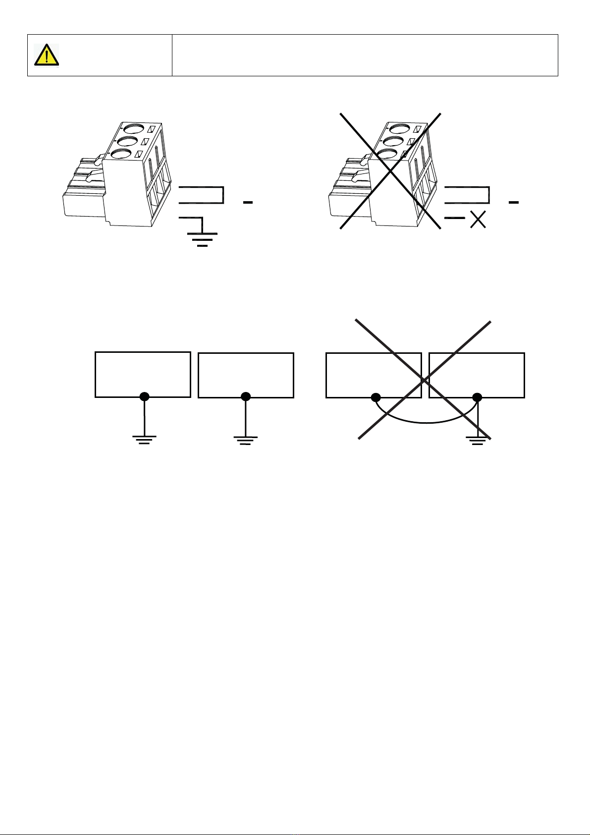
Grounding Resistance Below 100Ω
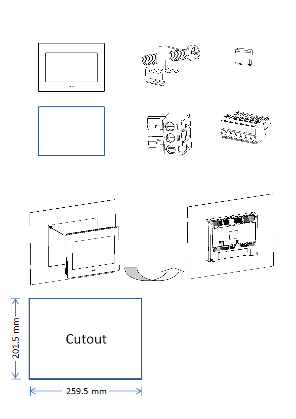
Dimension Cut-out 259.5 x 201.5 (mm)
4

4. Unpacking the Unit
FATEK HMI x1
Hook and Screw x7
FATEK PLC
Connector Rubber
Cover x1
A4 Double-sided Installation Guide x1
Power Connector x1
Pluggable Terminal
Block x1
5. Installation Procedures
zPush the HMI into the cutout until the
waterproof ring contacts the plate.
zInsert a hook into each mounting hole
on the HMI, and then tighten the
screws evenly with a moderate torque.
z
Failure to tighten the screws may
cause the HMI to fall, malfunction
or
short-circuit. Excessive tightening may
cause deformation.
The necessary
torque is about 0.16N·m.
5

6. Power Connection
zBe sure to connect the ground FG
terminal to a class-3 ground (Ground
resistance should not exceed 100Ω).
Try to make the ground wire as short
as possible.
zUse 28–12 AWG (0.5–1.5 mm
2
) wire
for the power connections.
7. Termination Switch
zP5102S/N/N1 HMI has a built-in termination resistor switch.
To enable or disable the termination resistor please follow the configuration
shown in the table below. The termination switch is for COM3 [RS-422 /
RS-485] and COM4 [RS-485].
zConfiguration of Termination Resistor Switch.
Termination Resistor
No. COM3 [RS-422] COM3 [RS-485] COM4 [RS-485]
Enable Disable Enable Disable Enable Disable
1 ON OFF OFF OFF OFF OFF
2 ON OFF OFF OFF OFF OFF
3 ON OFF ON OFF OFF OFF
4 ON OFF ON OFF OFF OFF
5 OFF OFF OFF OFF ON OFF
6 OFF OFF OFF OFF ON OFF
DC24V
+
FG
6

8. Pin-out of COM Ports
DB-9 Male Connector
PIN# COM1
[RS-232]
1 NC
*1
2 RX
3 TX
4 NC
5 GND
6 NC
7 RTS
8 CTS
9 NC
*1 NC: No Connection
Pluggable Terminal Block
PIN# COM3
[RS-422] COM3
[RS-485] COM4
[RS-485]
1 NC NC DATA+
2 NC NC DATA-
3 ISO_GND ISO_GND ISO_GND
4 RX+ NC NC
5 RX- NC NC
6 TX+ DATA+ NC
7 TX- DATA- NC
1234567
7

9. PLC Extension Tips
zFor compact size and saving space, using FATEK HB1 main units + B1
extension modules is recommended.
zThe rubber cover of the PLC connector can be taken off and placed into the
termination switch slot.
8
R
Pobrano z: https://panele-hmi.pl/panel-hmi-10-2-p5102s-fatek
This manual suits for next models
2
Table of contents
Other FATEK Network Hardware manuals