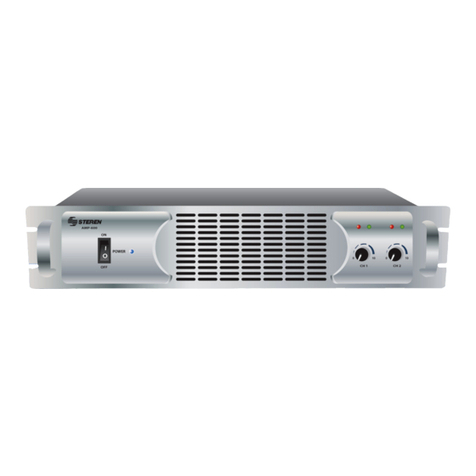
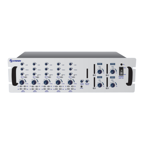
Steren AMP-160 User manual


Before using your new Powered PA Mixer / Amplifier, please
read this instruction manual to prevent any damage. Put it
away in a safe place for future references.
SECURITY INSTRUCTIONS
PRECAUTION
In order to reduce the risk of an electrical discharge, do not
remove the front or back covers. There are no pieces within the
device that can be fixed by the user. See a qualified technician.
ATTENTION
In order to reduce the risk of fire or electrical shock, do not ex-
pose this device to rain, humidity, or any other sources of water.
When this symbol appears, it warns of the
presence of a dangerous un-isolated voltage
within the device. This voltage may be strong
enough to constitute a discharge or electrical
shock danger.
When this symbol appears, it signals that the
following instructions are important for operation
and maintenance.
ENGLISH
ENGLISH-2
Before usin
g
y
our new Powered PA Mixer / Amplifier, please
read this instruction manual to prevent an
y
dama
g
e. Put it
a
wa
y
in a safe place for future references
.

Verify Line Voltage Before Use
Your new amplifier has been factory-configured for use with
115- volt AC line current. Connecting the amplifier to a line
voltage other than that for which it is intended can create a
safety and fire hazard, and may damage the amplifier.
If you have any questions about the voltage requirements for
your specific model, or about the line voltage in your area,
contact your selling dealer before plugging the unit into a wall
outlet.
Do Not Use Extension Cords
To avoid safety hazards, use only the power cord supplied with
your unit. If a replacement
cord is used, make certain that it is of a similar gauge. We do not
recommend using extension
cords with this product. As with all electrical devices, do not run
power cords under rugs or carpets or place heavy objects on
power cords.
Damaged power cords should be replaced immediately with
cords meeting factory specifications.
Handle the AC Power Cord Gently
When disconnecting the power cord from an AC outlet, always
pull the plug; never pull the cord. If you do not intend to use the
amplifier for a considerable length of time, disconnect the plug
from the AC outlet.
Do Not Open the Cabinet
There are no user-serviceable components inside this product.
Opening the cabinet may
present a shock hazard, and any modification to the product will
void your guarantee. If water
enters the unit, or any metal object such as paper clip, wire or
staple accidentally falls inside the cabinet, disconnect the unit
from the AC power source immediately and consult an
authorized warranty station.
ENGLISH
ENGLISH-3

Installation Location
- To ensure proper operation and to avoid the potential
for safety hazards, place the unit on a firm and level
surface. When placing the unit on a shelf, be certain that
the shelf and any mounting hardware can support the
amplifier’s weight.
- Make certain that the proper space is provided both
above and below the unit for ventilation. If the amplifier
will be installed in a cabinet or other enclosed area,
make certain that there is sufficient air movement within
the cabinet. Consult with your dealer or installer for more
information.
- Do not place the unit directly on a carpeted surface.
- Avoid installation in extremely hot or cold locations, in
an area that is exposed to direct sunlight or near heating
equipment.
- Avoid moist or humid locations.
- Do not obstruct the ventilation slots on the top of the
unit or place objects directly over them. Remember,
power amplifiers generate heat, and the heatsink fins
and ventilation slots that form part of the cabinet are
specially designed to remove this heat. Placing other
electronic equipment near these heat dissipation
systems may possibly affect the long-term reliability of
both your amplifier and the objects placed above it. The
carton and shipping materials used in protecting your
new amplifier were specially designed to cushion it from
the shocks and vibration of shipping. We suggest that
you save the carton and packing materials for use in
shipping if you move or if the unit ever needs repair.
Cleaning
When the unit gets dirty, wipe it with a clean, soft and dry cloth. If
necessary, first wipe the surface with a soft cloth slightly
dampened with mild soapy water, followed by a fresh cloth with
clean water. Wipe immediately with a dry cloth. Never use
benzene, thinner, alcohol or any other volatile cleaning agent.
ENGLISH
ENGLISH-4

Do not use abrasive cleaners, as they may damage the finish of
metal parts. Avoid spraying insecticide near the unit.
Moving the Unit
Before moving the unit, be certain to disconnect any
interconnection cords with other components,
and make certain that you disconnect the unit from the AC outlet.
ENGLISH
ENGLISH-5

FRONT PANEL
1.- Gain
This knob controls input gain. Turn
clockwise and the input will be
increased. Turn counter clockwise
and the input will be
decreased.
2.- Treble
This knob set high frequencies. Use
it to eliminate noises in high
frequencies or to enhance the sound
of cymbals, or high harmonics of
human voice. The gain range goes
from –10dB to 10dB, with a central
frequency of 10kHz
3.- Bass
This knob set low frequencies.
Enhances male voice and low
frequencies from guitars. The
system will sound bigger than what
it is. The gain range goes from
–10dB to +10dB, with a central
frequency of 100Hz
4.- Mute
Press to mute the signal output of
the selected channel
GAIN
1
TREBLE
2
BASS
3
MUTE
4
5
ENGLISH
ENGLISH-6
1
2
3
4

5.- Mute LED
Lights on when mute button was
pressed
6.- Volume
Use this knob to control the volume
level of the selected channel. If you
turn it to the right, the volume will
raise, if you turn it to the left, the
volume level will decrease.
7.- Zone selector
Press the desired buttons to assign
a zone. Whole zones can be
operated at the same time.
8.- Phone volume
Set the volume level of the device
plugged to Phone connector.
9.- Phone
The amplifier’s audio signal can be
sent to the connected headphones.
10 Monitor volume control
This knob allows you to set the
monitor volume output level.
11 Zone 1 volume level
Use this knob to control the volume
level of the Zone 1 signal output
12 LED VU-metre
Indicates the overall output signal
level
13 Monitor selector
Press Monitor, the signal from the
amplifier 1 will connect to monitor
volume. Press Monitor once again,
and the connection signal will be
cut. Other three buttons are
operated in the same way.
8
9
10
Phone
Volume Monitor
Volume
Phone
MUTE
Z3
Z1 Z2
Z4
Zone
Selector
VOL
4
5
6
7
MON
VOLUME
ZONE 1
11
12
13
ENGLISH
ENGLISH-7
5
6
7
8
9
10
11
12
13

14 PL
Lights on when the amplifier
is on.
15 On / Off switch
use this switch to power
on / off the amplifier.
REAR PANEL
16 Fan
When the temperature is under 50°C, the fan stops. But if the
temperature is over 50°C, the fan will starts to run and the speed
of the fan will be increased until the temperature decrease.
17 Power cord
Allows you to connect the supplied power cord.
1 Fuse
This fuse protects the alternating current circuit of the unit, and
can be replaced only in case of the fuse broke.
19 Voltage selector
Use this switch to select the voltage in accord to the zone where
you want to install the amplifier.
20 Monitor line out
This terminal allows you to connect other device, such as
amplifier, recorder, etc.
21 1W8ohm monitor
Use this terminal to connect small external speakers, which will
be powered by an auxiliary power amplifier, offering a 1W of
nominal output. Only the mixed audio signal coming from AUX
IN, is included I the output signal.
115V~ 230V~115V~ 230V~
G+
-
+TRG
Monitor
Line Out 1W 8
£[
Monitor Priority Tel. Paging
VolumeZone
Main Power
115/230V~50/60Hz
Ch.5
Line Ch.4
Line
Ch.4
Ch.3 Ch.2
Ch.1
TEL
Phantom
Line Mic Phantom
Line Mic
Phantom
Line Mic Zone 1 G +
-
Com 4
£[
8
£[
25V 70V 100V
Zone 2 G +
-
Com 4
£[
8
£[
25V 70V 100V
Zone 3 G +
-
Com 4
£[
8
£[
25V 70V 100V
Zone 4 G +
-
Com 4
£[
8
£[
25V 70V 100V
AC Fuse:
110-120V:T6.3AL 250V
220-240V:T3.15AL250V
Caution:
Replace fuse only with same and rated type!
Attention:
Afin de reduire le risque d'incendie remplacer seul par un
fusible de meme type!
Caution:
Toreduce the risk of fire or electric shock. Do not expose
this appliance to rain or moisture. Do not remove cover.
There are no user serviceable parts inside. Refer servicing
to qualified service personnel.
Attention:
Pour reduir les risques d' incendie ou de choc electrique
ne pas exposer a la pluie ou l' humidite. Ne pas enlever
le couvercle. Aucun reglage al' interieur.Pour reparation
consulter une personne qualifiee.
RISKOF ELECTRIC SHOCK
DONOT OPEN
CAUTION : SHOCK HAZARD - DO NOT OPEN
RISK OF FIRE-REPLACE FUSE AS MARKED.
Line Out Bal./Unbal. Power Amp. Output
CAUTION
16
20 21 22 23
24
25
19
17
18
26
27
28 29
26
POWER
ON
OFF
PL
14
15
ENGLISH
ENGLISH-8
14
15
16
17
18
19
20
21

What is more, the output signal is controlled only by the channel
4 and 5 volume control.
22 Priority terminal
When these terminals are in short-circuit (e.g. using an electrical
switch), the audio signals from channels 4 and 5 are attenuated.
23 AUX paging input
Use these terminals to connect an auxiliary signal. The input
features of Voice Priority function, which overrides all other input
signals once, an auxiliary message is sent. If you want to
deactivate this function permanently, contact to your dealer.
24 a) Zone
There are 4 dip switches, Move the switch up to select the zone
where you want to listen the signal sent by the phone line.
b) Volume
Allows you to set the audio signal output volume form the phone
line. When you don’t use the phone line, we recommend to use
the volume level to 0.
25 Line In
Use this connectors to plug an external audio source with a high
signal output level, such as AM/FM tuner, tape deck, CD player,
etc. Use sensitive input switches suitable for different devices.
You can connect devices with RCA connectors and
non-balanced signals.
26 Mic / Line channel (Mono)
These are channels 1, 2 and 3 and you can connect low
impedance - balanced microphones to XLR connector. Into the
¼” connector you can plug a microphone or line instrument. Do
not connect a non-balanced microphone to XLR connectors,
otherwise, the amplifier and the microphone can be damaged.
27 Phantom switch
If you move the switch to LINE position, you can connect an
audio source with a high output signal level in the channels 1, 2
and 3.
ENGLISH
ENGLISH-9
22
23
24
25
26
27

Placing the switch into MIC position, the channels 1, 2 and 3 can
be used to connect a dynamic microphone with a low
impedance.
Finally, if you place the switch to Phantom, the amplifier sends
energy to PIN 2 and 3, being perfect to use this connector to
plug condensed microphones. We recommend to use this switch
with the main volume to the minimum.
28 Balanced / non-balanced line out
These terminals can be used to connect other devices such as
amplifier, recorder, etc.
29 Power amplifier output
use these terminals to wire the speakers.
CONNECTIONS
Speaker
Horn speaker
Microphone
Desktop Microphone
Sound column
Contact
"VOICE PRIORITY"
Speaker Aux.signal
Mains
AM/FM tuner
CD player
Cassette recorder
Amplifier
Recorder
ENGLISH
ENGLISH-10
28
29

+ 100V70V25V
COM 4
-
G 8
Total impedance: 4ohm
+ 100V70V25V
COM 4
-
G 8
Total impedance: 8ohm
ENGLISH
ENGLISH-11

0 0 0
+ 100V70V25V
COM 4
-
G 8
25V 25V 25V
Connecting the speakers with a 25V output
0 0 0
+ 100V70V
25V
COM 4
-
G 8
70V 70V 70V
Connecting the speakers with a 70V output
ENGLISH
ENGLISH-12

SPECIFICATIONS
Input: 115/230V ~ 50/60Hz 2A max
Power output: 4 x 40Wrms
4 x 90Wpmpo
Frequency response: 50Hz – 17kHz (-3dB)
SNR: 72dB
Inputs / sensitivity - impedance: Channel 1 – 3 / XLR y ¼”:
balanced
Microphone: -42dB / -38dB – 600ohm,
balanced / non-balanced
Line: -26dB / -20dB – 15ohm,
balanced / non-balanced
Channel 4: -10dB 50kohm
Channel 5: 0dB 50kohm
Tone controls: Bass: +10dB – 100Hz
Treble: +10dB – 10kHz
Output for speakers / ohms: 4ohm, 8ohm
Output for speakers / volts: 25V – 70V – 100V
Monitor output: 1W rms
Phone output: 0,5W into 47ohm
Line out: 1,2V
Dimensions: 483 x 310 x 132mm
Weight: 33,29lb
Product design and specifications are subject to change,
without notice.
0 0 0
+ 100V70V25V
COM 4
-
G 8
100V 100V 100V
Connecting the speakers with a 100V output
P
roduct desi
g
n and specifications are sub
j
ect to chan
g
e,
without notice
.
ENGLISH
ENGLISH-13


Antes de utilizar su nuevo Amplificador para publidifusión
en 4 zonas de 160W, lea este instructivo para evitar
cualquier mal funcionamiento. Guárdelo para futuras
referencias.
INSTRUCCIONES DE SEGURIDAD
PRECAUCIÓN
Para reducir el riesgo de descargas eléctricas, no quite la tapa
(o parte posterior). No hay piezas que puedan ser reparadas por
el usuario en el interior; remita el servicio al personal calificado.
ATENCIÓN
Para reducir el riesgo de incendio o descargas eléctricas, no
exponga este aparato a la lluvia o la humedad.
Este símbolo siempre que aparece, le advierte
de la presencia de voltaje peligroso sin aislar
dentro del equipo, que puede ser
suficientemente fuerte para constituir un riesgo
de descarga.
Este símbolo siempre que aparece, le advierte
sobre instrucciones operativas y de
mantenimiento importantes.
ESPAÑOL
ESPAÑOL-2
A
ntes de utilizar su nuevo Am
p
lificador
p
ara
p
ublidifusión
e
n 4 zonas de 160W, lea este instructivo para evitar
c
ual
q
uier mal funcionamiento. Guárdelo
p
ara futuras
referencias
.

Verifique la línea de voltaje antes de utilizar el equipo
Su amplificador ha sido configurado de fábrica con un voltaje
predeterminado de 115Vca. Conectar el amplificador a una
línea de voltaje diferente a la que utiliza puede provocar fuego y
dañar el equipo.
Si tiene alguna pregunta acerca de los requerimientos de
voltaje, o acerca del voltaje que se utiliza en su área, contacte a
un distribuidor cercano antes de conectar el equipo al
tomacorriente.
No utilice extensiones
Para evitar daños al equipo, utilice únicamente el cable de
corriente suministrado con la unidad. Si utiliza un cable de
reemplazo, asegúrese de que cuenta con la mismas
características que el original. No se recomienda utilizar ninguna
extensión con este producto. Como todo equipo eléctrico, no
coloque el cable de energía por debajo de alfombras o tapetes
ni coloque objetos pesados encima de los cables.
Si el cable de energía se encuentra dañado debe ser
reemplazado inmediatamente con cables que cuenten con las
mismas especificaciones de fábrica.
Maneje el cable de energía con cuidado
Cuando desconecte el cable de energía del tomacorriente,
siempre jale de la clavija; nunca jale del cable. Si no piensa
utilizar el amplificador por un tiempo considerable, desconecte el
cable del tomacorriente.
No abra el gabinete
Dentro del producto no existen componentes que puedan ser
utilizados por el usuario. El abrir el gabinete puede causar un
choque eléctrico, y cualquier modificación al producto anulará la
garantía.
Si entra agua en la unidad, o cualquier objeto metálico como
grapas, clips o alambres caen accidentalmente dentro del
gabinete, desconecte la unidad de la corriente eléctrica inmedi-
atamente y consulte a distribuidor autorizado.
ESPAÑOL
ESPAÑOL-3

Locación de instalación
- Para asegurar la correcta operación y evitar posibles
daños al equipo, coloque la unidad en una superficie
firme y plana. Cuando coloque la unidad en un estante,
asegúrese de que el estante y cualquier equipo para
montar puede soportar el peso del amplificador.
- Asegúrese de que el equipo cuenta con la
suficiente ventilación, tanto en la parte superior como
inferior. Si el amplificador será instalado en un
gabinete u otra área cerrada, asegúrese de que existe
la suficiente rotación de aire dentro del gabinete.
Consulte a su distribuidor para mayor información.
- No coloque la unidad directamente sobre una
superficie tipo alfombra.
- Evite la colocación en lugares demasiado calientes o
fríos, o en lugares donde esté expuesto a la luz del sol
de forma directa así como de equipos que generen
calor.
- Evite las áreas húmedas.
- No obstruya las ranuras de ventilación ni coloque
objetos directamente sobre ellas. Recuerde, los
amplificadores de poder generan calor, y los disipadores
de calor y las ranuras de ventilación que forman parte
del gabinete están especialmente diseñados para
remover ese calor. Colocar otros equipos electrónicos
cerca de esos sistemas de disipación de calor
podrían afectar el rendimiento del amplificador y los
otros objetos colocados encima de él. El material de
empaque utilizado en la protección del amplificador han
sido diseñados especialmente para amortiguar las
vibraciones y los golpes durante la entrega. Le
sugerimos guardar el material de empaque en caso de
que necesite moverlo o llevarlo a reparación.
ESPAÑOL
ESPAÑOL-4

Limpieza
Cuando la unidad se encuentra sucia, límpiela con un paño
suave y seco. Si es necesario, limpie primero la superficie con
un paño ligeramente humedecido en agua jabonosa, seguido
por un paso seco. Nunca utilice benceno, thinner, alcohol u otro
agente de limpieza volátil. No utilice limpiadores abrasivos,
pueden dañar el acabo de las partes metálicas. Evite rociar
insecticida cerca de la unidad.
Moviendo la unidad
Antes de mover la unidad, asegúrese de desconectar cualquier
conexión con otros componentes, y asegúrese de desconectar
el equipo de la corriente eléctrica.
ESPAÑOL
ESPAÑOL-5

CONTROLES FRONTALES
1.- Ganancia
Esta perilla controla la ganancia de
entrada. Muévala en sentido de las
manecillas del reloj, y la entrada
se incrementará. Muévala hacia la
izquierda y la entrada decrecerá.
2.- Agudos
Este control ajusta las frecuencias
agudas. Puede utilizar para eliminar
los ruidos de las frecuencias altas
o para incrementar el sonido de los
platillos, o frecuencias altas de la
voz humana. El rango de ganancia
va de –10dB a 10dB con la
frecuencia central de 10kHz
3.- Graves
Este control ajusta las frecuencias
graves. Permite incrementar la voz
del hombre y las frecuencias graves
de las guitarras. El sistema sonará
más grande de lo que es. El rango
de ganancia va de los –10dB a los
+10dB y la frecuencia central es de
100Hz
4.- Silenciar
Desactiva la salida de señales de
audio del canal seleccionado.
GAIN
1
TREBLE
2
BASS
3
MUTE
4
5
1
2
3
4
ESPAÑOL
ESPAÑOL-6

5.- LED de silenciado
Enciende cuando el botón de
Silenciar es presionado.
6.- Volumen
Controla el volumen del canal
seleccionado. Si lo mueve hacia la
derecha, el volumen se
incrementará, si lo mueve a la
izquierda, el volumen disminuirá.
7.- Selector de Zona
Presione los botones deseados para
asignar una zona. Todas las zonas
pueden ser operadas al mismo
tiempo.
8.- Volumen de Fono
Permite ajustar el nivel del volumen
del equipo conectado a la entrada
Phone.
9.- Fono
La señal de audio del amplificador
puede ser enviada a un par de
audífonos conectados.
10 Volumen de monitor
Este control permite ajustar el nivel
de salida de señal al monitor
11 Volumen Zona 1
Permite controlar el nivel de
volumen de la salida de señal de la
Zona 1
12 Indicador gráfico
Indica el nivel total de salida de
señal
8
9
10
Phone
Volume Monitor
Volume
Phone
MUTE
Z3
Z1 Z2
Z4
Zone
Selector
VOL
4
5
6
7
MON
VOLUME
ZONE 1
11
12
13
5
6
7
8
9
10
11
12
ESPAÑOL
ESPAÑOL-7
Other manuals for AMP-160
1
Table of contents
Languages:
Other Steren Amplifier manuals

Steren
Steren BAF-1595 User manual

Steren
Steren AMP-200 User manual

Steren
Steren 208-100 User manual

Steren
Steren AMP-016 User manual

Steren
Steren AMP-040SD User manual

Steren
Steren AMP-011 User manual

Steren
Steren AMP-045CD User manual

Steren
Steren BAF-1280 User manual

Steren
Steren AMP-600 User manual

Steren
Steren AMP-120 User manual

Steren
Steren AMP-013 User manual

Steren
Steren AMP-040SD User manual

Steren
Steren AMP-020 User manual

Steren
Steren AMP-210CD User manual

Steren
Steren AMP-012 User manual

Steren
Steren AMP-020 User manual

Steren
Steren AMP-020/GTR User manual

Steren
Steren AMP-009 User manual

Steren
Steren EP-128 User manual

Steren
Steren AMP-005 User manual