Faza GARDEN User manual

1
Via G. Antoniucci, 19 – Zona Ind. Regnano – 06012 CITTÀ DI CASTELLO (PG) Italy
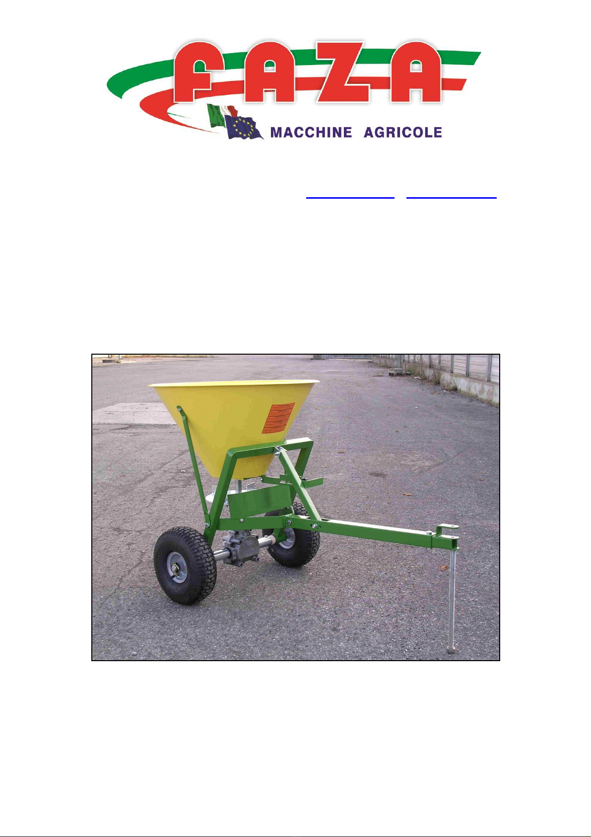
TRAILED FERTILIZER SPREADER
OPERATOR’S MANUAL
Mod. GARDEN
-
Please read this manual carefully before operating the equipment

2
Package contents
The package contains:
No. 1 Bag of findings including:
Item Part no.
Description Qty
2 GARDEN 2
Plastic bush 4
4 GARDEN 4
Hex-head screw 10x50 4
5 GARDEN 5
Self-locking nut M10 4
7 GARDEN 7
Fans 4
8 GARDEN 8
Hex-head screw 8x20 11
9 GARDEN 9
Self-locking nut M 8 20
12 GARDEN 12
Hex-head screw 8x50 9
13 GARDEN 13
Bush 2
15 GARDEN 15
Split pin 2
16 GARDEN 16
Pin L=190mm 1
18 GARDEN 18
Pin L=200mm 1
19 GARDEN 19
PVC shim 2
21 GARDEN 21
Hopper bush 1
22 GARDEN 22
Snap ring 1
26 GARDEN 26
Hook 1
27 GARDEN 27
Agitator 1
29 GARDEN 29
Hex-head screw 6x16 2
30 GARDEN 30
Self-locking nut M 6 2
33 GARDEN 33
Knob M 8x20 1
34 GARDEN 34
Washer M 10 1
35 GARDEN 35
Washer M 8 3
36 GARDEN 36
Wrench 2

3
No. 16 Loose pieces:
Item
Part no. Description Qty
1 GARDEN 1 Frame 1
3 GARDEN 3
Hopper support shaft Rt and Lt 2
6 GARDEN 6
Tow triangle shaft 1
10 GARDEN 10
Spreader disk 1
11 GARDEN 11
Reduction gear 1
14 GARDEN 14
Complete wheel with pin-locked
bush 1
17 GARDEN 17
Complete wheel with PVC bush 1
20 GARDEN 20
Hopper 50 Lt or 100 Lt 1
23 GARDEN 23
Draw bar 1
24 GARDEN 24
Tow hook 1
25 GARDEN 25
Strut 1
28 GARDEN 28
Guard 1
31 GARDEN 31
Open gate 1
32 GARDEN 32
Lever 1
37 GARDEN 37
Complete lever extension 1
No 1 Bag with Stickers and Manual

4
General Safety Regulations
In addition to the safety regulations given in this manual, always comply with the general rules for on-the-job
safety and health and the public Highway Code.
.
Before commencing work with the machine, it is necessary to become familiar with the operation of the
controls and operating devices.
.
Before switching
on the tractor make sure that all the protection guards are correctly assembled.
.
Do not handle the machine when the power take-off is rotating.
.
Do not exceed the maximum fertilizer load recommended by the manufacturer.
.
Do not use any equipment not recommended by the manufacturer, and do not modify the machine or its
components.
.
Before leaving the tractor make sure the spreader is lowered to the ground and switch off the tractor.
Read this manual carefully before operating the equipment.

5
Safety Decals
The equipment is fit with adhesives and plates with symbols on them. These safety symbols are to assist the
operator, helping him avoid possible risks of accidents during working, maintenance and storage.
This manual will explain the following symbols:
Symbol Description
Use protection gloves
Use safety eye glasses
The following symbols are attached to the equipment:
Symbol Description
Consult the operator's and servicing manual
Do not pass or stand near the equipment while in use
Danger for hands and/or feet

6
Safety and accident prevention rules
The operator of this fertilizer spreader must be competent and be in good physical condition, have good eye-
sight and must be able to co-ordinate the different functions. Moreover he must apply the established rules and
act with the necessary precaution while carrying out a job, so that he does not expose himself or other people to
danger.
The operator must put the indications given in this manual into practice and must also enable third persons to
assume their responsibilities.
The operator must act only after he is absolutely certain how to use the entire equipment.
He must not neglect machine maintenance.
During the job, the operator must be able to control the machine and oversee the area where the machine is
operating.
Never wear loose clothing: overalls without loose parts that can get caught in parts of the machine are
preferable.
Never work unless the work area has sufficient lighting.
Never make any emergency repairs on the machine in order to start or finish a job.
Check that the instruction/warning plates and adhesives are clean and easily seen and that the safety devices are
in place and well locked.
Never drink alcoholic beverages or take medicines before or during work or when carrying out maintenance on
the machine.
Always wear gloves and, if necessary, safety eye-glasses while servicing the fertilizer machine.
Never clean or oil parts of the fertilizer machine while in it is running.
Before starting work always check the conditions of the bolts and tighten them adequately.
Check if there are any foreign objects in the hopper and be careful not to drop the bag containing the fertilizer
into the hopper.
Never carry objects that could slip out of your trousers or breast-pockets while leaning over the machine.
Before leaving the driver’s seat always:
1. disconnect the power-take-off shaft
2. lower the fertilizer spreader to the ground
3. turn off the tractor engine
4. insert the parking brake and low gear
5. take the ignition key out of the control board
Never perform any work on the fertilizer spreader unless the machine is turned off.

7
INSTALLATION
First take the Frame (1) and install the 4 plastic bushes (2).
1
2
Take the hopper support shafts (3) and secure them to the tow triangle shaft (6) using the screws (4) and nuts (5)
as indicated in the figure. Be careful to leave the holes of the tow triangle shaft (6) facing up. Do not tighten the
nuts and bolts
3
5
4
6

8
Install the fan (7) on the disk (10) using the screws (8) and nuts (9). The assembly must be installed on the
reduction gear (11) using the screw (12) and nuts (9). Then insert the bushes (13) into the reduction gear (11)
using the screws (12) and nuts (9).
10
8
7
9
11
12
13
At this point take the wheel with the pin-locked bush (14) and install pin (16) with the split pin (15). Perform
the same operation for the wheel with the plastic bush (17) inserting pin (18) and secure with the split pin (15).
14 16 18
15 17 15

9
Now take this assembly and install it using the bush (13), screws (12) and nuts (9) as indicated in the figure.
Remember to insert the plastic bushes (19).
9
12
19 13
Install bush (21) on the Hopper using the snap ring (22).
22
21

10
Install the draw bar (23) with the part facing up as shown in the figure. Insert screw (4) and nut (5).
5
23
4
Secure the tow hook (24) on the draw bar (23) using the same screw (4) and nut (5).
24
23

11
Take the strut (25) and install on the draw bar (23) using screw (12) and nut (9). Make certain that the furthest
holes are closer to the draw bar (23).
MAX
25
23
Insert the screw (12) into hook (26) and install the assembly on the strut (25) using the screw (12) and nut (9) as
shown in the figure.
9
12
25
12
26

12
Install the agitator (27) on the hopper (20).
20
27
Then set the agitator (27) in the spreader disk as shown in the figure.
27

13
At this point, with the hopper set on the disk, install screw (12) which was previously set with hook (26) and nut
(9).
12
26
Then install the right and left hopper support shafts (3) using screws (8) and nuts (9) but do not tighten the nuts
and bolts.
3
8 – 9 - 35

14
Secure the agitator to the reduction gear using screw (12) and nut (9).
12 - 9
Install the guard (28) using screws (29) and nuts (30).
28
29 - 30
36
Insert the open gate (31).
31

15
At this point, take the lever (32) and install the knob (33) and washer (34). Then secure the lever to the gate
using screw (8) and nut (9).
34 32 8 - 9
33

16
WARNING:
Tightening the machine is an extremely important phase. Start with the hopper screws, keeping the hopper
perfectly flat with the spreader disk. First secure the centring screw,
then the side screws (8) and the hopper shaft support screws (4).
8
4

17
Regulating fertilizer spread
As shown in the figure, fertilizer spread can be regulated from 1 to 8 as needed.

18
Serial number and identity plate
Manufacturer:
Equipment: Fertilizer Spreader Mod. Garden
Identity plate:

19
Maintenance
Maintenance of your spreader is very important and must be done carefully. Good maintenance reduces
operating costs and increases the equipment lifespan.
Maintenance service
In this part of the manual we examine the most frequent maintenance operations:
After use
.
wash the machine with water
.
dry all
the metal parts carefully
.
grease all the moving parts of the machine
.
check and tighten all bolts
Periodic maintenance
.
change the oil and grease in the gear box after the first 30 hours of operation
.
thereafter repeat this operation every 250 hours of operation by
unscrewing the gear box drain cap and wait for the oil to drain out
completely
.
turn the machine so that the cap opening is in an ideal position and fill
the gear box with about 0.25 kg of new oil
.
check the metal parts which are under great strain during working conditions and if
necessary replace them
Maintenance before the unit is to be taken out of service
.
wash the machine with water and sodium carbonate, taking care to dry the machine
thoroughly
.
touch up the metal parts with paint if necessary, lubricate the moving parts with
grease and spray other parts with oil
.
protect the machine by covering it with a nylon or canvas tarpaulin and set it in a dry room and
off the ground

20
Table of contents
Popular Lawn And Garden Equipment manuals by other brands

Taconova
Taconova ES 5941 operating instructions

Horstmann
Horstmann CentaurStat 7 installation guide

Redexim
Redexim Speedseed Walk Behind User manual and parts book

Bio Green
Bio Green FLORABOOSTER LUM 200-60 manual

Suncast
Suncast WFWT300 owner's manual

Miracle-Gro
Miracle-Gro AeroGarden AG4501 quick start guide