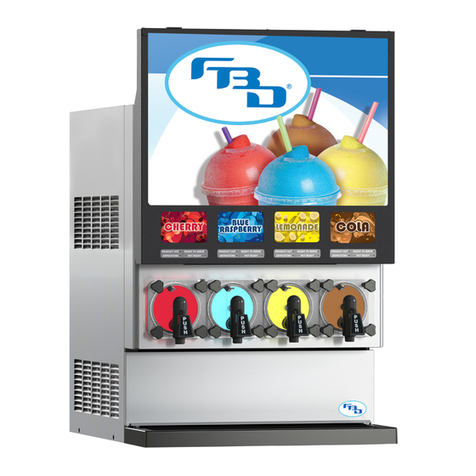
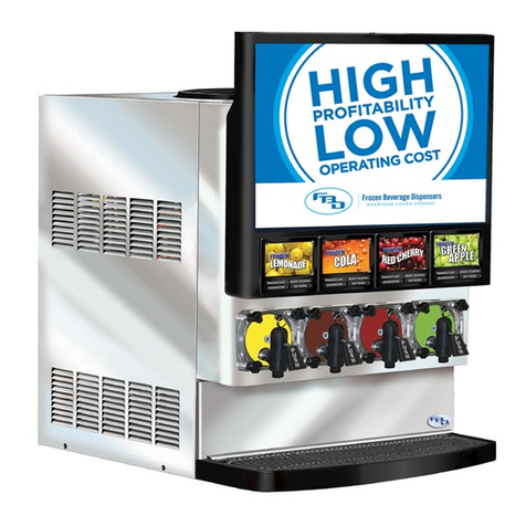
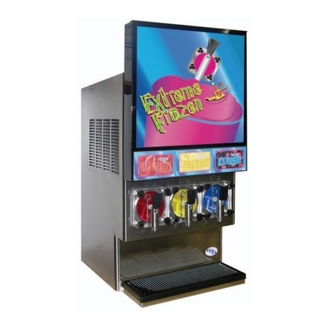
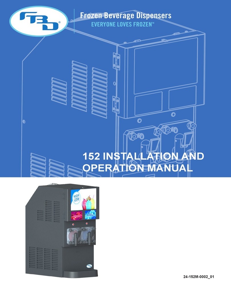
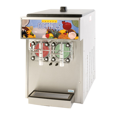
FBD 77 Series User manual

77X SERIES
INSTALLATION &
OPERATION MANUAL
771/772/773/774
24-77XM-0001_01
MODELS

This manual is for general informational purposes only and is not intended to cover every potential installation or operational
possibility. The parts and equipment addressed herein are warranted only to the extent covered by FBD’s Parts and Equipment
Warranty. FBD makes no express warranties as to any matter whatsoever and hereby disclaims all implied warranties including,
without limitation, the implied warranties of merchantability and fitness for any particular purpose. In no event shall FBD be liable
or obligated to any customer or to any third party for incidental, consequential, or special damages, regardless of the theory of
liability, arising out of, or in any manner related to FBD parts, equipment or any delay with respect to its delivery.
The information contained in this document is subject to change without notice.
© 2020 FBD Partnership, L.P. All Rights Reserved.

77X INSTALLATION & OPERATION MANUAL
771/772/773/774 MODELS
1
TABLE OF CONTENTS
1. SAFETY .................................................................................................................................... 3
1.1 ELECTRICAL........................................................................................................................3
1.2 COMPRESSED GASES ........................................................................................................3
1.3 GENERAL PRECAUTIONS....................................................................................................3
2. SPECIFICATIONS AND REQUIREMENTS................................................................................. 4
2.1 GENERAL REQUIREMENTS.................................................................................................4
2.2 ELECTRICAL REQUIREMENTS.............................................................................................4
2.3 DIMENSION AND WEIGHT SPECIFICATIONS.......................................................................5
3. RECEIVING AND UNPACKING DISPENSER ............................................................................. 6
3.1 RECEIVING..........................................................................................................................6
3.2 UNPACKING .......................................................................................................................6
4. INSTALLATION ........................................................................................................................ 6
4.1 GENERAL LOCATION REQUIREMENTS ...............................................................................6
4.2 DISPENSER MOUNTING .....................................................................................................6
4.3 INSTALLATION FOR EASIER SERVICE .................................................................................7
4.4 SELF-CONTAINED REFRIGERATION MODELS .....................................................................8
4.5 REMOTE-CONDENSING MODELS........................................................................................8
4.6 WATER-CONDENSING MODELS..........................................................................................8
4.7 UNIVERSAL GAS CONFIGURATIONS...................................................................................8
4.8 CONNECTING TO ELECTRICAL POWER...............................................................................9
4.9 SUPPLY CONNECTIONS....................................................................................................10
4.10 CONNECTING TO WATER SUPPLY ..................................................................................11
4.11 CONNECTING TO GAS SUPPLY .......................................................................................11
4.12 CONNECTING TO SYRUP SUPPLY...................................................................................11
5. STARTING UP THE DISPENSER ............................................................................................ 12
5.1 LEAK CHECK AND PRIME .................................................................................................12
5.2 INITIAL POWER UP ...........................................................................................................13
5.3 WATER FLOW RATE AND BRIX..........................................................................................14
5.4 FILLING BARREL AND STARTING .....................................................................................15
6. DISPENSER OPERATION ....................................................................................................... 16
6.1 FREEZE.............................................................................................................................16
6.2 OFF...................................................................................................................................16
6.3 DEFROST ..........................................................................................................................16
6.4 DRINK QUALITY ................................................................................................................16
6.4.1 DRINK TOO “FIRM” OR COLD ..................................................................................17
6.4.2 DRINK TOO “SLOPPY” OR WARM ............................................................................17
6.4.3 DRINK TOO HEAVY ..................................................................................................17
6.4.4 DRINK TOO LIGHT ...................................................................................................17
7. MENUS AND NAVIGATION .................................................................................................... 18
7.1 KEYPAD ............................................................................................................................18
7.2 HOME MENU ....................................................................................................................19
7.3 POP-UP MENU..................................................................................................................19
7.4 MENU TREE......................................................................................................................20
7.5 MAIN MENU .....................................................................................................................21
7.6 READOUTS MENU ............................................................................................................21
7.7 FAULT CODE HISTORY MENU...........................................................................................22
7.8 SERVICE MENU.................................................................................................................22
7.9 MAINTENANCE MENU......................................................................................................23
77X INSTALLATION & OPERATION MANUAL
771/772/773/774 MODELS
2
TABLE OF CONTENTS (CONTINUED)
7.10 SETTINGS MENU ............................................................................................................ 25
7.11 CLOCK AND SCHEDULE MENU....................................................................................... 28
7.12 DATE AND TIME MENU................................................................................................... 28
7.13 DEFROST SCHEDULE MENU........................................................................................... 29
7.14 AUTO DEFROST MENU ................................................................................................... 29
7.15 WAKE/SLEEP SCHEDULE MENU ..................................................................................... 30
7.16 MANUAL ON/OFF MENU ................................................................................................ 30
7.17 BEVTRAKTM MENU .......................................................................................................... 31
7.18 MODEM SETTINGS MENU............................................................................................... 31
7.19 MACHINE TOTALS MENU ............................................................................................... 32
7.20 RESTORE FACTORY SETTINGS MENU ............................................................................ 32
7.21 DIAGNOSTICS MENU ...................................................................................................... 33
8. CLEANING AND SANITIZING ................................................................................................. 34
8.1 GENERAL INFORMATION.................................................................................................. 34
8.2 DAILY CLEANING .............................................................................................................. 34
8.3 SANITIZING....................................................................................................................... 34
9. PREVENTIVE MAINTENANCE................................................................................................ 36
9.1 AIR FILTER CLEANING ...................................................................................................... 36
9.2 REAR SEAL REPLACEMENT .............................................................................................. 37
9.3 BACKFLOW PREVENTER MAINTENANCE ......................................................................... 38
9.4 SERVICING THE PRODUCT TRAY ...................................................................................... 38
10. TROUBLESHOOTING ........................................................................................................... 39
10.1 HOME MENU MESSAGES................................................................................................ 39
10.2 FAULT CODES................................................................................................................. 41
10.3 DIAGNOSTIC FAULT CODES............................................................................................ 48
11. DIAGRAMS AND SCHEMATICS ........................................................................................... 51
11.1 MOUNTING TEMPLATES................................................................................................. 51
11.2 FLOW DIAGRAMS (MULTI-FLAVOR DISPENSERS)........................................................... 54
11.3 FLOW DIAGRAMS (STANDARD DISPENSERS)................................................................. 56
11.4 ELECTRICAL WIRING DIAGRAMS (MULTI-FLAVOR DISPENSERS) ................................... 57
11.5 ELECTRICAL WIRING DIAGRAMS (STANDARD DISPENSERS) ......................................... 60
11.6 REFRIGERATION SCHEMATIC DIAGRAMS (MULTI-FLAVOR DISPENSERS) ..................... 63
11.7 REFRIGERATION SCHEMATIC DIAGRAMS (AIR-COOLED DISPENSERS).......................... 65
11.8 REFRIGERATION SCHEMATIC DIAGRAMS (REMOTE CONDENSING DISPENSERS)......... 67
11.9 REFRIGERATION SCHEMATIC DIAGRAMS (WATER-COOLED DISPENSERS).................... 68

77X INSTALLATION & OPERATION MANUAL
771/772/773/774 MODELS
3
1. SAFETY
1.1 Electrical
This dispenser must be properly electrically grounded to avoid possible fatal electrical shock or serious injury to the
operator. The power cord is provided with a three-prong grounded plug. If a three-hole grounded electrical outlet is not
available, use an approved method to ground the dispenser. Only qualified electricians should perform this task and the
work performed should meet all applicable codes.
The plug must be accessible at all times so that the dispenser can be shut o in case of emergency. Always disconnect
electrical power to the dispenser to prevent personal injury before attempting any internal maintenance. Only qualified
personnel should service internal components or electrical wiring.
1.2 Compressed Gases
Strict attention must be observed in the prevention of gas leaks in the entire gas and frozen drink system. If a gas leak is
suspected, immediately ventilate the contaminated area before attempting to repair the leak as prolonged exposure to high
concentrations of carbon dioxide (CO) or nitrogen (N) could lead to death. Personnel exposed to high concentrations of
CO gas may experience dizziness, asphyxiation, confusion, fatigue, headaches, and/or tremors which are followed rapidly
by loss of consciousness and suocation. Personnel exposed to high concentrations of N gas may experience dizziness,
drowsiness, nausea, vomiting, diminished mental alertness, and/or loss of consciousness.
All applicable laws and regulations pertaining to the use, storage, and transport of gas cylinders must be observed. To
avoid personal injury and/or property damage, always secure gas cylinders in an upright position with a safety chain. A gas
cylinder with a damaged or detached valve can cause serious personal injury.
When using compressed air for the active charge system, all air compressor equipment must be operated only by authorized
and trained personnel. The air intake should be from a clean, outside, fresh air source. If local laws and regulations
require it, screens or filters to clean the air should be used based on equipment manufacturer’s recommendations. Air
compressors should never be operated at speeds faster than the manufacturer’s recommendation and equipment should
not be allowed to become overheated.
1.3 General Precautions
This equipment, depending on the model, weighs up to 418 pounds (190 kilograms) when empty and is top-heavy. To
avoid personal injury or equipment damage, do not attempt to lift the dispenser without help. The use of a mechanical lift
is highly recommended. When lifting and positioning the dispenser, it should always stay in a vertical upright position.

77X INSTALLATION & OPERATION MANUAL
771/772/773/774 MODELS
4
2. SPECIFICATIONS AND REQUIREMENTS
2.1 General Requirements
†12” (304 mm) with side or back open-air conditions, 36” (914 mm) in equipment alcove.
2.2 Electrical Requirements
* All pressure values are listed in the manual in PSIG (kPag). However, the pressure readouts will be shown as “PSI” or
“kPa” on the dispenser display depending on the setting selected for “DISPLAY UNITS” (see Section 7.10).
Requirement
Syrup Supply Pressure 70 - 72 PSIG* (483 - 496 kPag)
Water Supply Pressure 30 PSIG (207 kPag) Minimum Flowing Pressure
70 PSIG (483 kPag) Maximum Static Pressure
Gas Supply Pressure 70 - 72 PSIG (483 - 496 kPag)
Clearance 3” (76 mm) Sides and Back,
12”-36” (304 mm - 914 mm) Top†
Refrigerant R404A
Requirement
Frequency 60 Hz
Operational Voltage 230 VAC ± 10%
Current
771 MFLV 20 A
772 20 A
772 MFLV 20 A
773 30 A
774 30 A

77X INSTALLATION & OPERATION MANUAL
771/772/773/774 MODELS
5
2.3 Dimension and Weight Specifications
Multi-Flavor Dispensers
Standard Dispensers
Specication 771 MFLV 772 MFLV
Width 17.0” (432 mm) 17.0” (432 mm)
Depth 32.5” (826 mm) 32.5” (826 mm)
Height - Short Door 34.0” (864 mm) 34.0”(864 mm)
Height - Tall Door 41.3” (1,049 mm) 41.3” (1,049 mm)
Weight - Empty 288 lb (131 kg) 310 lb (141 kg)
Weight - Operational 295 lb (134 kg) 333 lb (151 kg)
Weight - Shipping 304 lb (138 kg) 346 lb (157 kg)
Specication 772 773 774
Width 17.0” (432 mm) 20.3” (516 mm) 26.0” (660 mm)
Depth 32.5” (826 mm) 32.5” (826 mm) 32.5” (826 mm)
Height - Short Door 34.0” (864 mm) 34.0” (864 mm) 34.0” (864 mm)
Height - Tall Door 41.4” (1,052 mm) 41.4” (1,052 mm) 41.4” (1,052 mm)
Air-Cooled Dispensers
Weight - Empty 298 lb (135 kg) 359 lb (163 kg) 418 lb (190 kg)
Weight - Operational 321 lb (146 kg) 393 lb (178 kg) 464 lb (211 kg)
Weight - Shipping 338 lb (153 kg) 404 lb (183 kg) 468 lb (212 kg)
Remote Condensing Dispensers
Weight - Empty 283 lb (128 kg) 343 lb (156 kg) 400 lb (182 kg)
Weight - Operational 306 lb (139 kg) 377 lb (171 kg) 446 lb (202 kg)
Weight - Shipping 323 lb (147 kg) 388 lb (176 kg) 450 lb (204 kg)
Water-Cooled Dispensers
Weight - Empty 295 lb (134 kg) 356 lb (162 kg) 415 lb (188 kg)
Weight - Operational 318 lb (144 kg) 390 lb (177 kg) 461 lb (209 kg)
Weight - Shipping 335 lb (152 kg) 401 lb (182 kg) 465 lb (211 kg)

77X INSTALLATION & OPERATION MANUAL
771/772/773/774 MODELS
6
3. RECEIVING AND UNPACKING DISPENSER
3.1 Receiving
Each dispenser is tested and thoroughly inspected before shipment. At the time of shipment, the carrier accepts the
dispenser and any claim for damages must be made with the carrier. Upon receiving the dispenser from the delivering
carrier, carefully inspect carton for visible indication of damage. If damage is present, have carrier note same on bill of
lading and file a claim with the carrier.
3.2 Unpacking
A. Cut banding from shipping carton and remove carton by lifting up. Remove protective side panels and four
corner protectors.
B. If included, remove drip tray assembly and accessory kit from top packaging. Contact the dealer if any
parts are missing or damaged.
C. Remove side panels from dispenser.
D. Inspect dispenser for concealed damage. If evident, immediately notify delivering carrier and file a claim
against same.
E. If dispenser is received with a shipping board attached to the bottom, remove shipping board from bottom
of dispenser by accessing and removing the bolts located on the under side of the shipping board.
F. Lift dispenser up by the frame cross bracing and remove lower portion of carton.
4. INSTALLATION
4.1 General Location Requirements
Dispenser is intended for indoor use only. A flat, level location is required for proper installation. When using a counter,
ensure it will support the weight of the dispenser plus the weight of any equipment placed near it. See the specifications
section for equipment weights.
Adequate space above and behind the dispenser is required to allow:
1. Removal of side panels, if service is necessary.
2. Air circulation around vents on sides, back, and top of dispenser.
A well-ventilated room is required for the dispenser. The environment, however, should be stable and not subject to abrupt
changes in temperature. The dispenser should not be exposed to direct sunlight or chemicals.
4.2 Dispenser Mounting
Countertop - Flush Mounting: The most common installation is placing the dispenser directly on a countertop. If
permanently mounting to the countertop, the dispenser should be bolted down and a thin bead of silicone sealant should
be applied around the base of the frame. Remove the side panels before applying sealant and refer to the information in
Section 11.1 “Diagrams and Schematics” for the specific mounting dimensions by model.

77X INSTALLATION & OPERATION MANUAL
771/772/773/774 MODELS
7
Figure 4.1 Product Tray Pushed In
Space must be provided for the extra tubing to be coiled up
behind the dispenser. Take care that it does not get pinched
or kinked.
Figure 4.2 Product Tray Partially Pulled Out
Straight fittings allow the tubing to remain connected while
working on the tray.
Countertop - Leg Mounting: Another countertop option is to install 4” support legs (sold separately) to allow for
easy cleaning around and under the dispenser. The legs install easily into the same four holes used to bolt the frame
to the shipping pallet. As an added benefit, this installation typically meets state and local health department codes.
Base Cart: A roll-around base cart (sold separately) can be used when a suitable countertop location is not available.
Dispensers installed to base carts must be bolted to the cart to avoid the dispenser from falling o which could result in
serious injury or death. Once installed, seal the dispenser to the cart using a bead of clear silicone caulk around the base
of the frame.
4.3 Installation for Easier Service
The 77x series of dispensers have a removable product tray to help with servicing the dispenser. The tray may be either
completely removed (for access to back components) or it can partially slide out (for access to front components) as
shown in Figure 4.2. The dispenser must be properly installed to take advantage of these features.
Use the straight fittings found in standard FBD dispenser install kits (sold separately) when connecting the water, CO or
N gas, and syrup lines to the dispenser.
Allow for an extra 18 inches (46 cm) of tubing in the lines for standard dispensers, and 24 inches (61 cm) for multi-flavor
dispensers. This extra slack will be useful when the tray is later pulled out for service.

77X INSTALLATION & OPERATION MANUAL
771/772/773/774 MODELS
8
4.4 Self-Contained Refrigeration Models
Adequate clearance around the dispenser is required for proper air flow. Failure to provide proper clearance will reduce
capacity and can damage the refrigeration system. See the specifications page for clearance requirements. Avoid
enclosed installations if possible; recirculated hot discharge air from the dispenser can impact performance or damage
the system. Such installations require supplemental ventilation such as a fan with a thermal switch to remove the hot
discharge air.
An ambient temperature of no more than 75°F (24°C) provides the optimal capacity. As the ambient temperature increases,
the dispenser capacity decreases. It is essential that the HVAC system be sized to handle the additional heat load from all
self-contained, air-cooled dispensers. If ambient heat is a concern, FBD recommends a remote-condensing dispenser.
4.5 Remote-Condensing Models
Remote-condensing models utilize a condenser assembly external to the building and are designed for ambient
temperatures from -10°F to 120°F (-23°C to 49°C). This configuration removes the heat and fan noise from the inside
environment and reduces the air conditioning load during the warm season. Because air flow is not a high concern with
this set up, this style dispenser is suitable for enclosed spaces and zero side clearance installations (dispensers side-by-
side). Remote condensing models utilize a small air recirculation fan to assist in drying out any internal condensation. This
fan is located on the top of the dispenser and runs continuously. If your dispenser has an opening on the top panel for the
fan, do not stack objects on top of the dispenser as this will block the airflow and damage the fan.
4.6 Water-Condensing Models
Water-condensing models have specific water flow rate and temperature requirements. The minimum required volumetric
flow rate is 3.5 gallons (13.2 L) per minute and the allowable water inlet temperatures should not exceed 75°F (24°C).
Water flow rates below the recommended amount or temperatures in excess of recommended temperature will cause
significantly degraded performance and possibly damage the dispenser. Water-condensing models utilize a small air
recirculation fan to assist in drying out any internal condensation. This fan is located on the top of the dispenser and runs
continuously. If your dispenser has an opening on the top panel for the fan, do not stack objects on top of the dispenser
as this will block the airflow and damage the fan.
4.7 Universal Gas Configurations
All 77x multi-flavor dispensers come with “universal gas” options. The “universal gas” options provide multi-gas, multi-
drink functionality which allow for additional flexibility in configuration of the dispenser. For the 771 multi-flavor dispensers,
the universal option provides two gas connections - one which drives the pump and active charge system, and a second
which is injected into the product. For the 772 multi-flavor dispensers, three gas connections are provided - one for active
charge/pumps, one for injection into barrel 1 product, and one for injection into barrel 2 product.
The “Main Gas” connection which drives the water pump, active charge system, and pneumatic dispense valves can use
compressed air, CO, or N. The “Gas 1” and “Gas 2” (for 772 multi-flavor) can utilize COor Nfor injection into the
product.

77X INSTALLATION & OPERATION MANUAL
771/772/773/774 MODELS
9
Multi-drink functionality is accessed through the menu which allows the drink type (as defined by expansion) to be selected
for each barrel. The drink types available are dependent on which gas is currently selected for “Gas 1” or “Gas 2” (where
applicable). Please refer to Section 4.9 for additional information related to gas connections for the dispenser and Section
7.10 for instructions on configuring drink types.
4.8 Connecting to Electrical Power
The dispenser is shipped with a three-prong, locking-type plug. It will be either a 20 A or 30 A plug depending on the model.
The mating wall receptacle must match the amperage rating of the dispenser. If the plug on the dispenser is replaced with
an alternate, it must have the same amperage rating and provide a grounding prong. The dispenser must be connected
to a dedicated circuit with the proper amperage fuse rating; however, do not connect the dispenser to power at this time.
This will be done when going through the dispenser’s initial power up (Section 5.2).
The dispenser requires a single phase 230 VAC ± 10%. If the line voltage is above or below the required, a buck-boost
transformer must be used. Operation above or below the required voltage may damage the dispenser and cause
inconsistent performance. Operation outside the recommended voltage range also voids all warranties.
Remove the plug from the power cord and feed the cord through the strain relief located at the back of the dispenser.
Tighten the strain relief securely. Reinstall the plug on the power cord and check for continuity on the plug across both
“hot legs” and no continuity between each “hot leg” and ground.
Note: The voltage drop on the LCD between idle and run modes must not exceed 10 volts between the power source and
the machine. If it is greater than 10 volts then the power supply is inadequate and needs to be addressed by a certified
electrician.
Risk of Electric Shock: If the cord or plug becomes damaged, replace only with a cord and plug of the same type
provided by the manufacturer or service agency in order to avoid potential hazard.
Universal Conguration Drink Types
Dispenser Main Gas Gas 1 Gas 2 Available Drink Types
771
Multi-Flavor CO, N, or Air CO or N N/A CO: Medium Expansion and High Expansion
N: Medium Expansion
772
Multi-Flavor CO, N or Air CO or N CO or N CO: Medium Expansion and High Expansion
N: Medium Expansion

77X INSTALLATION & OPERATION MANUAL
771/772/773/774 MODELS
10
4.9 Supply Connections
The water, syrup, and gas connections can be found at the back of the dispenser. All dispensers will have a bulkhead
label near the bulkhead fittings illustrating which supply line connects to each fitting (Figure 4.3). The label will differ in
size and shape based on the dispenser model. Please refer to the “Bulkhead Fittings” table in this section for additional
information on the different connections.
Figure 4.3 Bulkhead Fittings Label Location
* “X” represents the barrel number for SYRUP connections, and the flavor number for FLAV connections.
Bulkhead Fittings
Fitting Label Description
H2O Water supply connection.
CO2 Carbon dioxide supply connection (for standard congurations).
N2 Nitrogen supply connection (for nitrogen congurations).
MAIN GAS Connection for gas driving pumps, active charge system, and pneumatic faceplate on
universal gas congurations. Can be compressed air, CO or N.
GAS 1 Connection for gas being injected into product (for multi-avor dispensers only). Can be
CO or N. Gas 1 supplies barrel 1 on universal gas congurations.
GAS 2 Connection for gas being injected into product (for multi-avor dispensers only). Can be
CO or N. Gas 2 supplies barrel 2 on universal gas congurations.
SYRUP X* Base syrup connection. The base avor syrup in a given barrel.
FLAV X* Flavor shot connection. The avor shot that will be mixed with a base syrup (on multi-
avor dispensers only).
SYRUP 4 SYRUP 3 CO
2
H
2
O
SYRUP 2 SYRUP 1
Artwork for 24-2403-0001_D
LABEL, BULKHEAD DIAGRAM, 774
Created 01/27/17 (Rev D), ECN 17-095
*Contact FBD Engineering Department for digital artwork files of layout with color specifications.
PANTONE BLACK C BRUSHED SILVER
SYRUP 4 SYRUP 3 CO
2
H
2
O
SYRUP 2 SYRUP 1
Artwork for 24-2403-0001_D
LABEL, BULKHEAD DIAGRAM, 774
Created 01/27/17 (Rev D), ECN 17-095
*Contact FBD Engineering Department for digital artwork files of layout with color specifications.
PANTONE BLACK C BRUSHED SILVER
SYRUP 4 SYRUP 3 CO
2
H
2
O
SYRUP 2 SYRUP 1
Artwork for 24-2403-0001_D
LABEL, BULKHEAD DIAGRAM, 774
Created 01/27/17 (Rev D), ECN 17-095
*Contact FBD Engineering Department for digital artwork files of layout with color specifications.
PANTONE BLACK C BRUSHED SILVER
SYRUP 4 SYRUP 3 CO
2
H
2
O
SYRUP 2 SYRUP 1
Artwork for 24-2403-0001_D
LABEL, BULKHEAD DIAGRAM, 774
Created 01/27/17 (Rev D), ECN 17-095
*Contact FBD Engineering Department for digital artwork files of layout with color specifications.
PANTONE BLACK C BRUSHED SILVER
SYRUP 4 SYRUP 3 CO
2
H
2
O
SYRUP 2 SYRUP 1
Artwork for 24-2403-0001_D
LABEL, BULKHEAD DIAGRAM, 774
Created 01/27/17 (Rev D), ECN 17-095
*Contact FBD Engineering Department for digital artwork files of layout with color specifications.
PANTONE BLACK C BRUSHED SILVER
SYRUP 4 SYRUP 3 CO
2
H
2
O
SYRUP 2 SYRUP 1
Artwork for 24-2403-0001_D
LABEL, BULKHEAD DIAGRAM, 774
Created 01/27/17 (Rev D), ECN 17-095
*Contact FBD Engineering Department for digital artwork files of layout with color specifications.
PANTONE BLACK C BRUSHED SILVER
SYRUP 4 SYRUP 3 CO
2
H
2
O
SYRUP 2 SYRUP 1
Artwork for 24-2403-0001_D
LABEL, BULKHEAD DIAGRAM, 774
Created 01/27/17 (Rev D), ECN 17-095
*Contact FBD Engineering Department for digital artwork files of layout with color specifications.
PANTONE BLACK C BRUSHED SILVER
SYRUP 4 SYRUP 3 CO
2
H
2
O
SYRUP 2 SYRUP 1
Artwork for 24-2403-0001_D
LABEL, BULKHEAD DIAGRAM, 774
Created 01/27/17 (Rev D), ECN 17-095
*Contact FBD Engineering Department for digital artwork files of layout with color specifications.
PANTONE BLACK C BRUSHED SILVER

77X INSTALLATION & OPERATION MANUAL
771/772/773/774 MODELS
11
4.10 Connecting to Water Supply
Water pipe connections and fixtures directly connected to a potable water supply shall be sized, installed, and maintained
in accordance with federal, state, and local codes.
Connect water line adapter to the bulkhead fitting labeled “WATER” or “H2O” on the back of the dispenser. The water
supply line connected to the bulkhead fitting should be a minimum 3/8” ID or larger if required by local codes. Before
installing, flush several gallons of water through a newly fabricated line to remove any debris. Installing a shutoff valve near
the connection will be helpful when removing the dispenser.
Do not turn on the water supply at this time.
Note: According to the National Sanitation Foundation (NSF), an ASSE 1022 approved backflow prevention device must
be installed on the water supply line before connecting to the dispenser. If needed, one can be purchased from FBD under
part number 12-2272-0001. The backflow device must have a line connected to the vent that diverts any flow to a drain.
Failure to divert flow can result in water overflow.
4.11 Connecting to Gas Supply
The gas supply may come from either an independent tank with a primary/secondary regulator or a bulk tank that supplies
other equipment. If the supply is from a bulk tank, tee off the main line and install a wall-mounted secondary regulator
set to 70 PSIG (483 kPag). Fabricate a 3/8” ID line from the secondary regulator (independent tank or wall mount) to the
rear of the dispenser and connect to the appropriate bulkhead fitting. This regulator should only supply gas to the frozen
beverage dispenser (and base cart if applicable). Installing a shutoff valve near the connection is recommended. For
dispensers with multiple gas connections, verify the correct gas is connected to the correct fitting. If the dispenser is on
a base cart with the BIBs and syrup pumps inside, then install a tee in the supply gas line to feed the syrup pumps.
Do not turn on the gas supply at this time.
4.12 Connecting to Syrup Supply
For installations requiring syrup lines less than 50 ft (15 m) in length, use tubing with a minimum ID of 3/8”. Run the syrup
lines from the pumps to the rear of the dispenser and connect to the proper syrup or flavor fitting.
For installations requiring syrup lines over 50 ft (15 m) in length, use tubing with a minimum ID of 1/2”. Using tubing of
any smaller diameter will lead to pressure fluctuations and false sold-out errors. Furthermore, consider installing booster
pumps on the supply lines. Increasing the regulated gas pressure on the syrup pumps (without exceeding the syrup
pump’s pressure rating) can also help maintain proper supply pressure at the dispenser.
In all situations, it is recommended to install a shutoff valve near the connection to the back of the dispenser to assist with
servicing or removing the dispenser.
Do not turn on the gas supply for the syrup pumps at this time.

77X INSTALLATION & OPERATION MANUAL
771/772/773/774 MODELS
12
5. STARTING UP THE DISPENSER
5.1 Leak Check and Prime
1Remove the side panels by loosening the two screws located at the bottom of the panel and then
lifting o the frame.
2Remove the drip tray by lifting up and pulling away, then remove access panel to expose the
solution modules.
3 Connect the BIB connectors to the syrup BIBs.
4Turn on the water and the gas supplies. Ensure both are owing to the dispenser.
Note: The water and syrup pumps will activate loudly until the lines are pressurized.
5 Thoroughly check for leaks at all connections.
6
Install a 1/4” ID tube on the sample port shown in Figure 5.1. Check that the water and syrup
shutos are on (as shown in Figure 5.2) and then open the sample valve and collect the water/
syrup in a cup. Continue to prime until syrup ow has been established and all air has been
removed from the lines. Discard the samples. Repeat for all barrels.
Sample Valve
(shown open)
Sample Port
(tube not shown)
Figure 5.1 Sample Valve on Solution Module

77X INSTALLATION & OPERATION MANUAL
771/772/773/774 MODELS
13
5.2 Initial Power Up
Plug the dispenser into the power supply and verify the dispenser turns on by looking at the LCD located behind the
merchandiser. The display should be on the home screen showing the status of the barrels (see Section 7 for additional
information on keypad buttons and how to navigate through menus). If the firmware has just been updated, then the
dispenser will prompt the operator to answer the following questions:
1. Desired language.
2. Number of barrels.
3. Dispenser serial number.
After responding to the prompted questions, the home screen will be displayed.
Next, a few verifications will need to be made:
For multi-flavor dispensers, the following will also need to be completed:
† Use the display pressure readouts when adjusting the settings.
‡ The water pump output pressure should be 15 to 20 PSIG (103 to 138 kPag) above the unregulated gas (or “Main Gas”)
pressure. See the troubleshooting section if the pressures are not correct.
§ The dispenser will tolerate fluctuations in regulated gas (or “Gas #1”/”Gas #2”) from 50 to 70 PSIG (345 to 483 kPag)
because it will automatically compensate. It is best to ensure during setup that the regulated gas is as close to 60 PSIG
(414 kPag) as possible.
1Press the green check button and then select the MENU option. Next, select the READOUTS option.
2 Press the COMMON button.
3 Verify the line voltage is at 230V ± 10%.
4Verify the unregulated gas pressure (or“Main Gas”for universal gas configurations) is between 70 to
72 PSIG (483 to 496 kPag)†and adjust the regulator if needed.
5 Verify the water pressure is between 85 to 92 PSIG (586 to 634 kPag)†. This is not adjustable.‡
6Verify the regulated gas pressure (or “Gas #1”/”Gas #2” for universal gas congurations) is
approximately 60 PSIG (414 kPag) and adjust the regulator if needed.§
7 Press the BARREL button.
8Verify the syrup pressures are between 70 and 72 PSIG (483 and 496 kPag) and adjust the back
room regulator if needed.
9Dispense product from the sample valve after adjusting any pressures. This will restabilize to the
new pressure.
10 Press the FLAVOR button in the READOUTS menu.
11 Verify the syrup pressures for each of the avors are between 70 and 72 PSIG (483 and 496 kPag)
and adjust the regulator if needed.

77X INSTALLATION & OPERATION MANUAL
771/772/773/774 MODELS
14
5.3 Water Flow Rate and Brix
The water flow rate and brix for each barrel must be verified and adjusted for optimal performance. Use the following
procedure to adjust the water flow rate and set the brix for each barrel:
For multi-flavor dispensers, the flavor injection modules will also need to be calibrated. Please refer to the Multi-Flavor
Addendum (24-M4MF-0001) for the calibration procedure.
The target brix for most sugar flavors is between 13.5 and 15. The target brix for most “light” flavors will be lower, usually
between 9 and 10. Check the specifications for the flavors if unsure of the target brix.
Note: Light or diet products have a low brix and can cause problems with the dispenser if not properly set up. Although
these products have ingredients to replace the antifreezing properties of sugar, they can still create excessive ice if not
carefully brixed according to their specifications. Low brix issues will be associated with events such as audible ice
scraping during freeze and low beater problems.
1 Turn the syrup shuto valve to the o position (Figure 5.2).
2
Adjust the water ow rate to 1.5 oz/sec (44.4 ml/sec) by dispensing water from the solution module
through the sample port for 10 seconds into a measuring cup. The amount measured should be 15
oz (444 ml). Turn the ow control clockwise to increase the ow and counterclockwise to reduce
the ow.
Note: The WATER AND BRIX CALIBRATION screen under the MAINTENANCE MENU can be used to
help with timing.
3Turn the syrup shuto valve to the on position and dispense a cup of uid from the sample port to
establish a stable ow.
4
Once a good water and syrup mixture is obtained, dispense a 16 oz sample and measure the
sample brix with a refractometer. Be sure to thoroughly mix the sample rst by pouring back and
fourth between two cups.
5Turn the syrup ow control counterclockwise to decrease the brix. Turn the syrup ow control
clockwise to increase the brix.
6 Dispense and discard several samples after adjusting the brix.
Water Flow
Control Syrup Flow
Control
Sample Port
Sample Valve
(closed position
shown)
Water Shutoff
Valve (open
position shown)
Syrup Shutoff
Valve (open
position shown)
Turning Clockwise
Increases Flow Rate
+
–
Turning Counterclockwise
Decreases Flow Rate
Flow Rate Adjustment
Figure 5.2 Solution Module

77X INSTALLATION & OPERATION MANUAL
771/772/773/774 MODELS
15
5.4 Filling Barrel and Starting
The barrel, or freeze chamber, must be purged of air before filling with product. Purge the air by activating the gas solenoid
and then using the relief valve on the faceplate (Figure 5.3) to relieve air until all air has been displaced by gas*. Failure to
displace the air with gas will result in poor drink quality.
* Remember to deactivate gas solenoid upon completion.
1Navigate to the SERVICE MENU and then select the MAINTENANCE MENU. Go to the PURGE/FILL/
DRAIN BARREL menu.
2Highlight the desired barrel and then press the GAS PURGE button. Follow the prompts until the
process has completed.
3
Press the FILL BARREL button to begin lling with product. Follow the prompts until the barrel
is full (about 90% of the barrel) and then press the END button. Use the relief valve to relieve
pressure in the barrel (Figure 5.3).
4 Once all barrels have been lled, return to the home menu.
5Defrost the barrel(s) by pressing the green check mark button then selecting DEFROST. This will
defrost the highlighted barrel and establish “baseline.”
6If you want to proceed to a freeze cycle right after the defrost cycle then press the green check
mark button again and select ON.
7When the LCD display shows READY, the barrel is ready to be conditioned. Dispense several drinks
until lighter color product begins forming in the faceplate.
Relief Valve
Figure 5.3 Relief Valve Location on Various Faceplate Types
Relief Valve Relief Valve

77X INSTALLATION & OPERATION MANUAL
771/772/773/774 MODELS
16
6. DISPENSER OPERATION
6.1 Freeze
To freeze the product, press the up or down arrows on the keypad to select the desired barrel, then press the green check
button and select ON. If the product is liquid, it will take four to ten minutes per barrel (depending on temperature of
product) to complete the initial freeze cycle. Dispense drinks until product near faceplate lightens in color indicating the
barrel is properly conditioned.
6.2 O
There are two options for turning off the dispenser. The first is to turn off one barrel at a time. To turn off individual barrels,
highlight the desired barrel in the home menu, then press the green check button and select OFF. Alternatively all barrels
can be stopped by pressing the red hand button to the left of the screen and then confirming with the green check button.
6.3 Defrost
To maintain optimal drink quality, the product in the barrel must be periodically defrosted because ice crystals grow in size
over time and degrade the consistency and texture of the drink. The best drink quality is always right after defrost and
refreeze. Naturally, it is ideal for the dispenser to be ready to serve drinks at all times, so a balance between defrost and
up time must be maintained. During times of high volume dispensing, a barrel can go longer without defrosting while low
volume periods should defrost every three to four hours.
Most dispensers are configured to execute automatic defrosts to maintain optimal product quality (please refer to Sections
7.13 and 7.14 for directions on setting up defrost times). If a defrost is required outside automatic set times either for
drink quality or service, a manual defrost can be completed by highlighting the desired barrel in the home menu and using
the green check button to select DEFROST. It will take about eight to twelve minutes to defrost (depending on the activity
of the other barrels). Unless the barrel is stopped prior to initiating defrost, it will remain ON and a freeze cycle will begin
after the completion of defrost.
6.4 Drink Quality
Many factors can affect the quality of a frozen beverage such as time since last defrost, brand of syrup used, and the local
water quality. There can even be drink quality differences between the various flavors within a given brand. Because
of these factors, the dispenser drink quality settings are designed to be easily adjusted to compensate for these natural
differences or even to adjust the drink quality for personal preferences.
There are two settings that can be adjusted for each barrel to change drink quality: the FREEZE ADJUSTMENT, which
controls how frozen the drink is, and the EXPANSION ADJUSTMENT, which controls how much gas is injected into the
product. Both of these adjustments are electronic settings; therefore, no tools are required to make an adjustment. The
type of adjustment will be determined based on the drink characteristic that needs to be changed. Please note that a
barrel that has been idle for hours, such as overnight, will produce a wetter, heavier drink. It is best to dispense a few
drinks to recondition the barrel. Consider the condition of the product in the barrel before making a judgment on the drink
quality.

77X INSTALLATION & OPERATION MANUAL
771/772/773/774 MODELS
17
6.4.1 Drink Too “Firm” or Cold
A drink that is over-frozen will tend to be very cold, below 22°F (-5.5°C), and can be considered hard and difficult to
suck through a straw. It can also be lighter in weight than a properly frozen drink and tends to collapse in the cup after
being dispensed. To raise the temperature of the drink, increase the setting found in the FREEZE ADJUSTMENT menu.
It will take several compressor cycles before the product in the barrel has reconditioned to the new setting.
6.4.2 Drink Too “Sloppy” or Warm
A drink that is not frozen enough will tend to be above 27°F (-2.8°C) and will be considered “wet” or “loose” and may
not stand up in the cup. It can also be heavier in weight than a properly frozen drink. To freeze the drink harder, lower
the setting in the FREEZE ADJUSTMENT menu. It will take several compressor cycles before the product in the barrel
has reconditioned to the new setting.
6.4.3 Drink Too Heavy
A drink with not enough gas will be heavy and may look dark in the barrel. To increase the gas content in the drink,
increase the setting in the EXPANSION ADJUSTMENT menu. Approximately ten 16 oz drinks will need to be dispensed
before the product in the barrel has reconditioned to the new setting.
6.4.4 Drink Too Light
A drink with too much gas will be very light and may even collapse in the cup. To reduce the amount of gas in the drink,
lower the setting in the EXPANSION ADJUSTMENT menu. Approximately ten 16 oz drinks will need to be dispensed
before the product in the barrel has reconditioned to the new setting.

77X INSTALLATION & OPERATION MANUAL
771/772/773/774 MODELS
18
7. MENUS AND NAVIGATION
7.1 Keypad
The keypad is the user interface point and allows for control of the dispenser and navigation of the menus. Please review
the keypad layout (Figure 7.1) to familiarize yourself with the interface.
• Select Button (green): This button confirms the current selection or action.
• Stop-All Button (red): This button will turn off all barrels. A confirmation by the green select button is required.
• Up/Down Arrow Buttons (yellow): These buttons move the selection cursor up and down. Press the select button
to confirm the selection.
• Soft Key (screen-labeled) Buttons (black): These buttons change function depending on the menu currently
being displayed. The function will be displayed below the top buttons and above the lower buttons.
ICON ACTION
Returns the display to the home menu.
Returns the display to the previous menu.
Moves the selection cursor to the right.
Moves the selection cursor to the left.
Stop-All
Button
Select Button
Soft Key (screen-labeled) Buttons
Up/Down
Navigation
Buttons
Figure 7.1 Keypad
Screen Icon Legend
Other manuals for 77 Series
1
This manual suits for next models
7
Table of contents
Other FBD Beverage Dispenser manuals
Popular Beverage Dispenser manuals by other brands

Perlick
Perlick DC Series Installation and operation instructions

Sentinel
Sentinel PA0220 user manual

Cornelius
Cornelius SPIRIT 414384-XXX Illustrated parts list

Perlick
Perlick HP15TS-3 A Series installation manual

Electrolux Professional
Electrolux Professional SORBY DREAM 1 Operator's manual

Bunn
Bunn 34000.0079 Programming manual