FBD 77 Series User manual

772 / 773 / 774
24-2396-0001/Rev C 07/30/2013

TABLE OF CONTENTS
TABLE OF CONTENTS.....................................................................................................................................2
SAFETY .............................................................................................................................................................4
ELECTRICAL...............................................................................................................................................4
CARBON DIOXIDE (CO2)...........................................................................................................................4
GENERAL PRECAUTIONS.........................................................................................................................4
LEGAL ...............................................................................................................................................................4
SPECIFICATIONS .............................................................................................................................................5
GENERAL REQUIREMENTS – ALL DISPENSERS...................................................................................5
DISPENSER SPECIFIC REQUIREMENTS ................................................................................................5
DISPENSER SPECIFICATIONS.................................................................................................................5
INSTALLATION.................................................................................................................................................6
GENERAL LOCATION REQUIREMENTS........................................................................................................6
SELF CONTAINED REFRIGERATION MODELS.......................................................................................6
REMOTE CONDENSING MODELS............................................................................................................6
DISPENSER MOUNTING............................................................................................................................6
CONNECTING TO ELECTRICAL POWER.................................................................................................7
CONNECTING TO WATER SUPPLY .........................................................................................................7
CONNECTING TO CO2 SUPPLY...............................................................................................................7
CONNECTING TO SYRUP SUPPLY..........................................................................................................8
MENUS AND NAVIGATION..............................................................................................................................8
KEYPAD ......................................................................................................................................................8
HOME MENU...............................................................................................................................................9
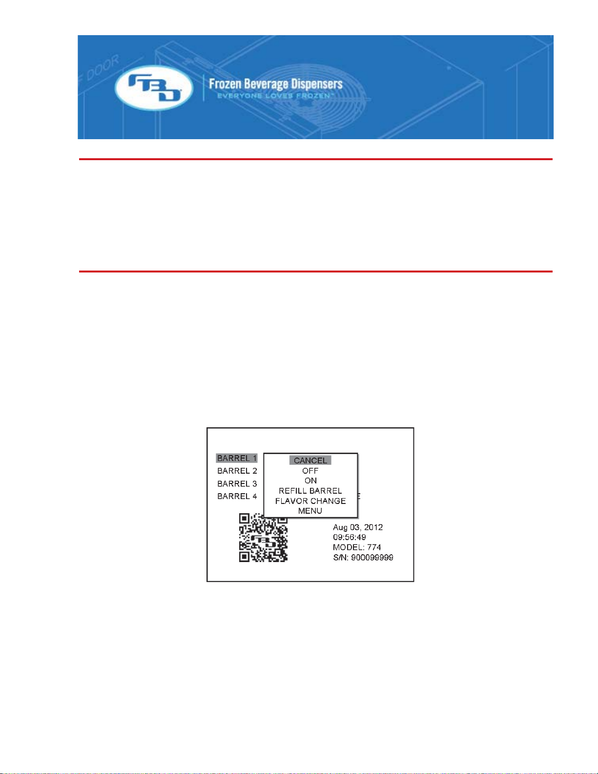
POPUP MENU.............................................................................................................................................9
MENU TREE..............................................................................................................................................10
MAIN MENU ..............................................................................................................................................11
READOUTS MENU ...................................................................................................................................11
FAULT CODES MENU..............................................................................................................................12
SERVICE MENUS.....................................................................................................................................12
MAINTENANCE OPTIONS MENU............................................................................................................13
SETTINGS MENU .....................................................................................................................................13
CLOCK AND SCHEDULE MENU..............................................................................................................14
DATE & TIME MENU.................................................................................................................................15
DEFROST SCHEDULE MENU .................................................................................................................15
AUTO DEFROST MENU...........................................................................................................................16
WAKE/SLEEP MENU................................................................................................................................16
MANUAL ON/OFF MENU..........................................................................................................................17
BEVTRAK MENU.......................................................................................................................................17
MODEM SETUP........................................................................................................................................18
MACHINE TOTALS MENU........................................................................................................................18
RESTORE FACTORY SETTINGS MENU.................................................................................................19
DIAGNOSTICS MENU...............................................................................................................................19
STARTING UP THE DISPENSER...................................................................................................................20
LEAK CHECK AND PRIME.......................................................................................................................20
INITIAL POWER UP..................................................................................................................................21
BRIXING....................................................................................................................................................21
FILLING BARREL AND STARTING..........................................................................................................23
DISPENSER OPERATION..............................................................................................................................24
FREEZE.....................................................................................................................................................24
OFF .........................................................................................................................................................24
DEFROST..................................................................................................................................................24
DRINK QUALITY .......................................................................................................................................24
DRINK TOO “FIRM” OR COLD.................................................................................................................24
2

TABLE OF CONTENTS (CONTINUED)
DRINK TOO “SLOPPY” OR WARM..........................................................................................................24
DRINK TOO HEAVY..................................................................................................................................25
DRINK TOO LIGHT...................................................................................................................................25
DEFROSTING ...........................................................................................................................................25
CLEANING AND SANITIZING ........................................................................................................................26
GENERAL INFORMATION........................................................................................................................26
DAILY CLEANING.....................................................................................................................................26
SANITIZING...............................................................................................................................................27
ROUTINE MAINTENANCE..............................................................................................................................28
AIR FILTER CLEANING............................................................................................................................28
REAR SEAL REPLACEMENT...................................................................................................................28
BACKFLOW PREVENTER MAINTENANCE ............................................................................................29
TROUBLESHOOTING.....................................................................................................................................30
HOME MENU MESSAGES.......................................................................................................................30
FAULT CODES..........................................................................................................................................31
DIAGNOSTIC FAULT CODES..................................................................................................................33
MOUNTING TEMPLATES...............................................................................................................................37
PLUMBING SCHEMATIC DIAGRAM..............................................................................................................39
WIRING SCHEMATIC DIAGRAM ...................................................................................................................40
REFRIGERATION SCHEMATIC DIAGRAM...................................................................................................42
3
FBD Partnership, LP
• P.O. BOX 18597 • SAN ANTONIO, TX 78218 USA •
• 210-637-2800 • FAX 210-637-2844 • www.fbdfrozen.com •
• FBD TECHNICAL SUPPORT • 1-866-323-2777 •
•TECHNICAL SUPPORT FAX 1-210-637-2832 •

SAFETY
Electrical
This dispenser must be properly electrically grounded to avoid possible fatal electrical shock or serious injury to
the operator. The power cord is provided with a three prong grounded plug. If a three-hole grounded electrical
outlet is not available, use an approved method to ground the dispenser. Only qualified electricians should
perform this task and the work performed should meet all applicable codes.
Always disconnect electrical power to the dispenser to prevent personal injury before attempting any internal
maintenance. Only qualified personnel should service internal components of electrical wiring.
Carbon Dioxide (CO2)
Strict attention must be observed in the prevention of CO2 gas leaks in the entire CO2 and soft drink system.
If a CO2 gas leak is suspected, immediately ventilate the contaminated area before attempting to repair the
leak. Personnel exposed to high concentrations of CO2 gas will experience tremors which are followed rapidly
by loss of consciousness and suffocation.
To avoid personal injury and/or property damage, always secure CO2 cylinders in an upright position with a
safety chain. Should the valve become accidentally damaged or broken off, a CO2 cylinder can cause serious
personal injury.
General Precautions
This equipment, depending on the model, weighs up to 460 pounds. To avoid personal injury or damage, do
not attempt to lift the dispenser without help. The use of a mechanical lift is highly recommended. Because the
dispenser is top heavy be sure to maintain in a vertical, upright position when lifting and positioning.
LEGAL
This Manual is for general informational purposes only and is not intended to cover every potential installation
or operational possibility. The parts and equipment addressed herein are warranted only to the extent covered
by FBD’s Parts and Equipment Warranty. FBD makes no express warranties as to any matter whatsoever and
hereby disclaims all implied warranties including, without limitation, the implied warranties of merchantability
and fitness for any particular purpose. In no event shall FBD be liable or obligated to customer or to any third
party for incidental, consequential, or special damages, regardless of the theory of liability, arising out of, or in
any manner related to FBD parts, equipment or any delay with respect to its delivery
4
This document contains proprietary information which is protected by copyright. All rights reserved.
© 2013 FBD Partnership, L.P. All Rights Reserved
The information contained in this document is subject to change without notice.

5
SPECIFICATIONS
General Requirements – All Dispensers
Requirement All Dispensers
Syrup supply pressure 70 - 72 PSIG (4800 – 5000 kPa)
Water supply pressure 70 - 72 PSIG (4800 – 5000 kPa)
CO2 supply pressure 70 - 72 PSIG (4800 – 5000 kPa)
Voltage Single Phase, 200 – 254 VAC
Clearance 3” (76 mm) sides or back, 36” (914 mm) top
Dispenser Specific Requirements
Requirement 772 773 774
Electrical circuit – 60 Hz 20 A 30 A 30 A
Dispenser Specifications
Requirement 772 773 774
Width 17.0” (432 mm) 20.3” (516 mm) 26.0” (660 mm)
Depth 32.3” (820 mm) 32.3” (820 mm) 32.3” (820 mm)
Height 41.4” (1052 mm) 41.4” (1052 mm) 41.4” (1052 mm)
Weight - empty 298 lbs (135 kg) 359 lbs (163 kg) 418 lbs (190 kg)
Weight - operational 321 lbs (146 kg) 393 lbs (178 kg) 464 lbs (210 kg)
Weight - Shipping 338 lbs (153 kg) 404 lbs (183 kg) 468 lbs (212 kg)

INSTALLATION
General Location Requirements
A flat, level location is required for proper installation. When using a counter, ensure it will support the weight
of the dispenser plus the weight of any equipment placed near it. See the specifications page for specific
equipment weights.
Self Contained Refrigeration Models
Adequate clearance around the dispenser is required for proper air flow. Failure to provide proper clearance
will reduce capacity and can eventually damage the refrigeration system. See the specifications page for
clearance requirements.
Be careful of enclosed, or “doghouse”, installations that can re-circulate hot discharge air. Installations such
as this require supplemental ventilation to remove the hot discharge air. A fan with a thermal switch is a good
option. Airflow from the fan should be at least 850 CFM.
Although the dispenser will operate in temperatures up to 104°F, an ambient temperature is 75°F will provide
the optimal capacity. As the ambient temperature increases, the dispenser capacity decreases.
Because this equipment is designed for high capacity, a self contained air
cooled dispenser will reject a large amount of heat into the environment. It
is essential that the HVAC system be able to handle this heat load. The
average heat load over time that is rejected into the environment is shown
in the table. If this is a concern then a remote condensing model might be
considered instead.
Model Average Heat Load
772 5,000 Btu/Hr
773 6,250 Btu/Hr
774 6,250 Btu/Hr
Remote Condensing Models
Remote condensing models utilize a condenser assembly external to the building and are designed for
ambient temperatures from -10°F to 120°F. This configuration removes the heat and fan noise from the inside
environment and reduces the air conditioning load during the warm season. Because air flow is not a
high concern with this set up, this style dispenser is suitable for enclosed spaces and zero side clearance
installations (dispensers side by side).
Remote condensing models utilize a small air recirculation fan to assist in drying out any internal
condensation. This fan is located on the top of the dispenser and runs continuously. Do not stack objects on
top of the dispenser as this will block the airflow and damage the fan.
Dispenser Mounting
Countertop - Flush Mounting: When the dispenser is mounted on a counter top, one method of installation
is to set the dispenser directly on top of the counter top. If permanently mounting to the counter top, use the
mounting information located in the “Dispenser Mounting” section of this manual to drill holes in the counter
top. Once installed, with side panels removed, seal the dispenser to the countertop using bead of clear silicone
caulk around the base of the frame.
Countertop - Leg Mounting: Another counter top option is to use support legs that raise the dispenser four
inches off the counter top (Purchased separately. Contact customer service). This allows easy cleaning under
the dispenser and meets most state and local health department codes. The legs mount to the same frame
6

7
locations as the counter top mounting bolts.
Base Cart: A roll-around base cart (Purchased separately, contact customer service) can be used when a suit-
able counter top location is not available or it is desired that the BIB’s and syrup pumps be located with the
dispenser. If a base cart is used, the dispenser must be secured to the cart using 3/8”-16 UNC bolts. Failure
to do so can result in serious injury should the dispenser fall off the cart. Once installed, seal the dispenser to
the cart using bead of clear silicone caulk around the base of the frame.
Connecting to Electrical Power
The dispenser is shipped with a 3 prong, locking type plug, either a 20A or 30A, depending on the model.
The mating wall receptacle must be a NEMA L-620-R or a NEMA L-630-R to match the amperage rating of
the dispenser. If the plug on the dispenser is replaced with an alternate, it must have the same amperage
rating and provide a grounding prong. The dispenser must be connected to a dedicated circuit with the proper
amperage fuse rating.
Note the voltage drop on the LCD between idle and run modes. If it is greater than 10 volts then the power
supply is inadequate and needs to be addressed by a certified electrician.
Caution, Risk of Electric Shock. If the cord or plug becomes damaged, replace only with a cord and plug of
the same type.
Do not connect the dispenser to power at this time.
Connecting to Water Supply
Note: According to the National Sanitation Foundation (NSF), an ASSE 1022 approved back flow prevention
device must be installed on the water supply line before connecting to the dispenser. If needed, one can be
purchased from FBD under part number 12-2272-0001. The back flow device must have a line connected to
the vent that diverts any flow to a drain. Failure to do this can result in a flooded establishment!
Water pipe connections and fixtures directly connected to a potable water supply shall be sized, installed, and
maintained in accordance with federal, state, and local codes.
The water supply line should be 3/8” ID minimum. Flush several gallons of water through a newly fabricated
line to remove any debris. Connect to the fitting labeled “H20” on the rear of the dispenser using a 1/4” flair
nut and washer. Installing a shutoff valve near the connection will be helpful when removing the dispenser.
Do not turn on the water supply at this time.
Connecting to CO2 Supply
The CO2 supply may come from either an independent tank with a primary/secondary regulator or a bulk
tank that supplies other equipment. If the supply is from a bulk tank then the supply will most likely be at 110
to 120 PSIG. If this is the case, tee off the main line and install a wall mount secondary regulator set to 70
PSIG. Fabricate a 3/8” ID line from the secondary regulator (independent tank or wall mount) to the rear of
the dispenser and connect to the bulkhead fitting labeled “CO2” using a 1/4” flair fitting. This regulator should
only supply CO2 to the frozen beverage dispenser. Installing a shutoff valve near the connection will be
helpful when removing the dispenser.
If the dispenser is on a base cart with the BIB’s and syrup pumps inside then install a tee in the supply CO2
line to feed the syrup pumps.
Do not turn on the CO2 supply at this time.

Connecting to Syrup Supply
Installations requiring tubing runs over 50 feet may encounter pressure fluctuation issues due to
excessive pressure drop and subsequently cause false sold out conditions. Use at least 1/2” ID tubing in these
situations. Also consider installing booster pumps on the supply lines. Increasing the regulated CO2 pressure
on the syrup pumps can also help maintain proper syrup pressure at the dispenser. Be sure not to exceed the
pressure rating of the syrup pump.
Fabricate 3/8” ID lines from the syrup pumps to the rear of the dispenser and connect to the proper syrup
bulkhead fittings using a 1/4” flair fitting (each barrel has a fitting that is labeled). Installing a shutoff valve near
the connection will be helpful when removing the dispenser.
Do not turn on the CO2 supply at this time.
MENUS AND NAVIGATION
Keypad
The keypad is the user interface point and allows for control of the dispenser and navigation of the menus.
Please review the keypad layout below to familiarize yourself with the interface.
• Select button (green): This button confirms the current selection or action.
• Stop all button (red): This button will turn off all barrels. A confirmation by the green select button is
required.
• Up/Down arrow buttons (yellow): These buttons move the highlighted selection up and down. Press the
select button to confirm the selection.
• Soft key (screen-labeled) buttons (black): These buttons change function depending on the menu currently
being displayed. The function will be displayed below the top buttons and above the lower buttons.
Stop all button
Select button
Soft ke
y
(
screen-labeled
)
buttons
Up/Down
Navigation
buttons
READY
BARREL 2 SYRUP OUT
BARREL 3 DEFROSTING
BARR EL 4 W AITING TO FREEZE
Aug 03, 2012 MODEL: 774
09:56:49 S/N: 900099999
BARREL 1
8

9
Home Menu
The home menu is shown above. This menu shows the status of all barrels, allows control of all barrels
and is the launching point to the sub menus. Press the green button while a barrel is highlighted to perform
actions to that barrel such as defrost or turn on or off. Pressing the green arrow will also allow access to the
sub menus.
Messages may appear on the home screen from time to time depending on the current activity or error. For a
complete listing of these messages please see the “home menu display messages” section of this manual.
Popup Menu
The popup menu allows the user to do the following:
• Start or stop the highlighted barrel
• Defrost the highlighted barrel
• Refill the highlighted barrel (when partially empty)
• Perform a flavor change on the highlighted barrel
• Proceed to the sub menus.
The popup menu is accessed by pressing the green button when the home screen is displayed.

10
Menu Tree
The menu is divided up into two levels. The first is the “store level” that is intended for the store operator.
The second level is the service level that is intended only for a trained service technician. Below is a visual
representation of the menu tree. For more information about each menu, see the descriptions that follow.
STORE LEVEL SERVICE LEVEL
To access the service menu, highlight “MENU” in the pop-up and then simultaneously press the green select
key and the bottom center soft key.
The soft keys on the sub menus are similar on all screens:
BUTTON ACTION
Returns the display to the home menu.
Returns the display to the previous menu.
>>> Moves the highlighted selection to the column on the right.
<<< Moves the highlighted selection to the column on the left.

11
Main Menu
The main menu allows the user to view the
• Readouts (pressures, temperatures, etc)
• Access the fault code history
• Access the service menu.
Readouts Menu
The readouts menu shows the current status of all temperature and pressure sensor readings, line voltage
and other pertinent information about the operation of the dispenser. Some readouts are common to the unit
and others are side, or barrel, specific. Press the “barrel” or “common” soft key button the switch between the
two readouts.

12
Service Menus
The service menus are intended for use by a trained service technician only. To access these menus, makes
sure “MENU” is highlighted in the pop-up and then press the green check button and the bottom center soft
key button (blank) simultaneously.
Fault Codes Menu
The fault code menu provides a list of the last twenty fault codes with the date and time of occurrence and
resolution. When the green button is pressed, additional details about the highlighted error are shown,
including a QR code. Scan the QR code with a smart phone to see detailed troubleshooting steps. For a
complete listing of fault codes that can be displayed please see the “Fault Code Definition” section of this
manual.

13
Maintenance Options Menu
The maintenance menu is for purging, filling and draining the barrels. There are three routines; all of which are
semi-automated and eliminate the need to manually turn solenoids on and off. Follow the on-screen prompts
to complete each process.
• Gas Purge: This procedure is used after the faceplate has been removed and there is air in the barrel.
It will purge the air from the barrel and replace with CO2. Use this process before filling the barrel. The
process will fill the barrel with CO2 three times before automatically ending.
• Drain Barrel: This process will assist in draining a liquid barrel (defrost first if needed). The user must
terminate this process by pressing the END button once the barrel is empty.
• Fill Barrel: This process fills the barrel with product. The user must terminate this process by pressing
the END button once the barrel is full.
All processes may be terminated at any time by pressing the END button.
Settings Menu
The settings menu has several items that are adjustable:
SERIAL#: Set the serial number of the unit. This is used for Bevtrak reporting.
BARRELS: Define the number of barrels for the dispenser.
DISPLAY UNITS: Set the unit of measurement to English or SI.
SYRUP TYPE: Set the syrup type to “FCB” or “Fountain.” Note: The unit changes internal settings based
on the syrup type.

14
There are also two sub-menus that affect the quality of the drink:
CARBONATION ADJUSTMENT: The amount of carbonation in the drink can be adjusted in this menu. The
adjustment ranges from “MAX CO2” (lots of carbonation!) to an un-carbonated drink. Select the barrel # and
adjust the bar graph up or down. Note: Approximately ten 16 oz drinks will need to be dispensed before the
product in the barrel has re-conditioned to the new settings.
FREEZE ADJUSTMENT: The viscosity of the drink can be adjusted by highlighting and selecting the
appropriate barrel. The adjustment allows the service agent to make the drink more liquid or more frozen.
Note: It will take several compressor cycles before the product in the barrel has re-conditioned to the new
settings.
Clock and Schedule Menu
The clock and schedule menu contains the following several sub-menus:

15
Date & Time Menu
The dispenser date and time is set in this menu. The time is in 24 hour format. The Daylight Saving feature
can also be activated and the start and end dates are adjustable. Refer to your country’s specific DST sched-
ule to set the start and end dates.
For example: In the USA, DST begins the second Sunday in March and ends on the first Sunday in November.
The example shown has been set according to this schedule.
Defrost Schedule Menu
The defrost menu allows for easy adjustment of the defrost times for barrel #1 and then the delay time between
barrels. For example, assume on a four barrel dispenser the delay time is set to 60 minutes and the first defrost
is at 03:00. Barrel #1 will defrost at 03:00, barrel #2 will defrost at 04:00, barrel #3 at 05:00 and barrel #4 at
06:00. There can be up to six defrosts per barrel per day. A time of 00:00 means no defrost is scheduled.
Each defrost time also has a day of the week setting. If the day of the week is capitalized then the dispenser
will defrost at that time on that day. If the day of the week is lowercase then the dispenser will skip that defrost
time on that day.
There are also predefined defrost schedules available. Contact FBD for details on the various schedules.

16
Auto Defrost Menu
In addition to a preset defrost schedule, the dispenser has an automatic defrost feature. This allows the
dispenser to dynamically adjust the time between defrost cycles based on customer activity.
When the auto defrost feature is enabled there are also “black out windows” that can be programmed. These
windows prevent any defrost cycles from occurring during that period. Up to three windows can be specified
and the start and end times for each window must be designated.
Note: A defrost schedule and auto defrost can be used simultaneously.
Wake/Sleep Menu
The wake/sleep feature makes the dispenser wake up and go to sleep automatically. This feature is useful
for locations that are closed overnight. The wake and sleep times can be different for each day of the week
or common for all days.

17
Manual On/Off Menu
The manual on/off menu allows the service technician to turn on and off any solenoid, motor or status light in
the dispenser. This is useful when purging the barrels or troubleshooting the dispenser.
Note: For protection, all solenoids will automatically turn off after 6 minutes
Bevtrak Menu
BevTrak is a reporting system for FBD beverage equipment. It allows the equipment owner to monitor the
status and sales performance of their dispensers via an internet browser. Bevtrak connects to the internet
via a GSM modem (cell phone technology) or through a Wi-Fi connection. The dispenser will have only one
connection method installed.
The serial number must be entered and Bevtrak must be enabled to utilize this service. Also, you will need to
create a customer login portal on the Bevtrak website (www.bevtrak.com). Contact FBD sales for assistance
setting up an account.

18
Modem Setup
The are several different modems that may be used so the correct modem must be selected. If a GSM modem
is used then the correct SIM provider must be selected as well. After both selections have been correctly
entered, select the “CONFIGURE MODEM” option to complete the process. Contact customer support for
assistance.
Machine Totals Menu
The machine totals menu provides various totals that the dispenser records such as the number of compressor
cycles or operating time for various components. This information can be useful when evaluating the through-
put or diagnosing problems with the dispenser.

19
Restore Factory Settings Menu
The restore menu allows a service technician to restore the dispenser settings to factory default. This can be
useful when too many settings have been changed and the dispenser is not operating at optimal conditions.
When restoring factory settings, certain settings can be retained such as the defrost schedule, auto defrost
blackout times, language and units (English or SI). Select which settings are to be retained before restoring
the factory settings.
Diagnostics Menu
The diagnostics is a powerful feature of the 77X. Any time a malfunction is suspected, the best option for the
service technician is to first run the diagnostic sequence for the system involved. This can eliminate hours of
guesswork and parts swapping.
There are three diagnostic sequences:
1. Refrigeration: This sequence will help identify any component failure in the refrigeration system such
as compressor, condenser fan, refrigeration or defrost solenoids and low or over charge issues.
2. Beater Circuit: This sequence will help identify any component failure in the beater circuit system such
as the beater motor and capacitors.
3. Fill Circuit: This sequence will help identify any component failure in the fill circuit system such as
solution or CO2 solenoids or any leaks in the product delivery system.
To begin, determine what the possible issue with
the unit may be select the appropriate diagnostic
sequence. Initiate the sequence and let it perform its
checks. You may be asked to perform some manual
operations or asked questions to proceed with the
process. If any errors are found, the display will note
the error and provide an error code. Refer to the “Error
Codes from Manual Diagnostic Sequence” in this
manual to diagnose the cause of the error.

20
STARTING UP THE DISPENSER
Leak Check and Prime
1 Remove the side panels by loosening the two screws located at the bottom of the panel and
then lifting off the frame.
2 Remove the drip tray by lifting and pulling forward and then remove the splash plate and front
cover to expose the solution modules.
3 Connect the BIB connectors to the syrup BIBs.
4 Establish the water supply and the CO2 supply. Note: the water and syrup pumps will
activate until the lines are pressurized.
5 Thoroughly check for leaks at all connections.
6 Install a ¼” I.D. tube on the sample port shown below. Open the sample valve and collect
the water/syrup in a cup. Continue to prime until syrup flow has been established and all air
has been removed from the lines. Discard the samples.
7 Repeat for all barrels.
Sample Valve on Solution Module
Sample Valve
(shown closed)
Sample port
(tube not shown)
Other manuals for 77 Series
1
This manual suits for next models
3
Table of contents
Other FBD Beverage Dispenser manuals