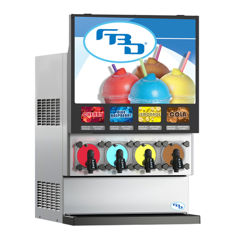
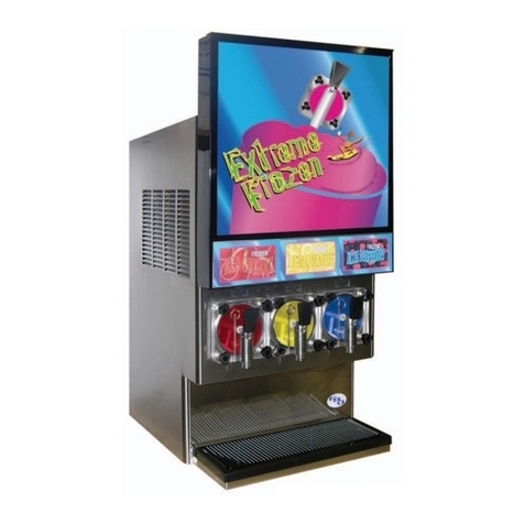
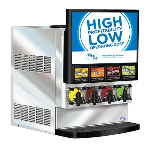
FBD 37 Series User manual

37X SERIES
INSTALLATION &
OPERATION MANUAL
372/373 MODEL
24-37XM-0001_01

37X INSTALLATION & OPERATION MANUAL
372/373 MODEL
1
TABLE OF CONTENTS
1. SAFETY ......................................................................................................................................3
1.1 ELECTRICAL........................................................................................................................3
1.2 CARBON DIOXIDE (CO)......................................................................................................3
1.3 GENERAL PRECAUTIONS....................................................................................................3
2. LEGAL ........................................................................................................................................3
3. SPECIFICATIONS ........................................................................................................................4
3.1 GENERAL REQUIREMENTS.................................................................................................4
3.2 ELECTRICAL REQUIREMENTS.............................................................................................4
3.3 DIMENSION AND WEIGHT SPECIFICATIONS.......................................................................4
4. RECEIVING AND UNPACKING DISPENSER .................................................................................5
4.1 RECEIVING..........................................................................................................................5
4.2 UNPACKING .......................................................................................................................5
5. INSTALLATION ...........................................................................................................................5
5.1 GENERAL LOCATION REQUIREMENTS ...............................................................................5
5.2 SELF-CONTAINED REFRIGERATION MODELS .....................................................................6
5.3 DISPENSER MOUNTING .....................................................................................................6
5.4 CONNECTING TO ELECTRICAL POWER...............................................................................6
5.5 CONNECTING TO WATER SUPPLY ......................................................................................7
5.6 CONNECTING TO COSUPPLY............................................................................................8
5.7 CONNECTING TO SYRUP SUPPLY.......................................................................................8
6. STARTING UP THE DISPENSER..................................................................................................9
6.1 LEAK CHECK AND PRIME ...................................................................................................9
6.2 INITIAL POWER UP ...........................................................................................................10
6.3 BRIXING............................................................................................................................11
6.4 FILLING BARREL AND STARTING .....................................................................................12
7. DISPENSER OPERATION ..........................................................................................................13
7.1 FREEZE.............................................................................................................................13
7.2 OFF...................................................................................................................................13
7.3 DEFROST ..........................................................................................................................13
7.4 DRINK QUALITY ................................................................................................................13
7.5 DRINK TOO “FIRM” OR COLD ...........................................................................................14
7.6 DRINK TOO “SLOPPY” OR WARM .....................................................................................14
7.7 DRINK TOO HEAVY ...........................................................................................................14
7.8 DRINK TOO LIGHT ............................................................................................................14
7.9 DEFROSTING ....................................................................................................................14
8. CLEANING AND SANITIZING ....................................................................................................15
8.1 GENERAL INFORMATION..................................................................................................15
8.2 DAILY CLEANING ..............................................................................................................15
8.3 SANITIZING.......................................................................................................................15
9. PREVENTIVE MAINTENANCE ...................................................................................................17
9.1 AIR FILTER CLEANING ......................................................................................................17
9.2 REAR SEAL REPLACEMENT ..............................................................................................18
9.3 BACKFLOW PREVENTER MAINTENANCE .........................................................................19
10. MENUS AND NAVIGATION .....................................................................................................20
10.1 KEYPAD ..........................................................................................................................20
10.2 HOME MENU ..................................................................................................................21
10.3 POP-UP MENU ...............................................................................................................21
10.4 MENU TREE....................................................................................................................22
10.5 MAIN MENU ...................................................................................................................23
10.6 READOUTS MENU ..........................................................................................................23

37X INSTALLATION & OPERATION MANUAL
372/373 MODEL
2
TABLE OF CONTENTS (CONTINUED)
10.7 FAULT CODE HISTORY MENU......................................................................................... 24
10.8 SERVICE MENU............................................................................................................... 24
10.9 MAINTENANCE MENU.................................................................................................... 25
10.10 SETTINGS MENU .......................................................................................................... 26
10.11 CLOCK AND SCHEDULE MENU..................................................................................... 27
10.12 DATE AND TIME MENU................................................................................................. 28
10.13 DEFROST SCHEDULE MENU ........................................................................................ 28
10.14 AUTO DEFROST MENU ................................................................................................. 29
10.15 WAKE/SLEEP SCHEDULE MENU ................................................................................... 29
10.16 MANUAL ON/OFF MENU .............................................................................................. 30
10.17 BEVTRAKTM MENU......................................................................................................... 30
10.18 MODEM SETTINGS MENU ............................................................................................ 31
10.19 MACHINE TOTALS MENU ............................................................................................. 31
10.20 RESTORE FACTORY SETTINGS MENU .......................................................................... 32
10.21 DIAGNOSTICS MENU .................................................................................................... 32
11. TROUBLESHOOTING.............................................................................................................. 33
11.1 HOME MENU MESSAGES................................................................................................ 33
11.2 FAULT CODES................................................................................................................. 35
11.3 DIAGNOSTIC FAULT CODES............................................................................................ 38
12. DIAGRAMS AND SCHEMATICS ............................................................................................... 40
12.1 MOUNTING TEMPLATES................................................................................................. 40
12.2 FLOW DIAGRAM.............................................................................................................. 42
12.3 372 ELECTRICAL WIRING DIAGRAM ............................................................................... 43
12.4 373 ELECTRICAL WIRING DIAGRAM ............................................................................... 46
12.5 REFRIGERATION SCHEMATIC DIAGRAM ........................................................................ 49
12.6 REFRIGERATION SCHEMATIC DIAGRAM ........................................................................ 50
APPENDICES* .............................................................................................................................. 51
APPENDIX A: 372 "NITROFUB" ............................................................................................. 52
Dispenser Appendix Annotation Symbol
372 Nitrofub A NF
* While Sections 1-12 contain information specific to the common configuration of the 37X dispenser, the Appendices detail information for
various unique configurations. If you are the owner of a unique configuration please refer to the Appendix that coincides with your dispenser.
An annotation symbol will be added to each section where additional information is being provided on the Appendices for that specific
dispenser configuration. The dispenser type, appendix, and annotation symbol are listed below.

37X INSTALLATION & OPERATION MANUAL
372/373 MODEL
3
1. SAFETY
1.1 Electrical
This dispenser must be properly electrically grounded to avoid possible fatal electrical shock or serious injury to the
operator. The power cord is provided with a three-prong grounded plug. If a three-hole grounded electrical outlet is not
available, use an approved method to ground the dispenser. Only qualified electricians should perform this task and the
work performed should meet all applicable codes.
Always disconnect electrical power to the dispenser to prevent personal injury before attempting any internal maintenance.
Only qualified personnel should service internal components or electrical wiring.
1.2 Carbon Dioxide (CO) NF*
Strict attention must be observed in the prevention of COgas leaks in the entire COand frozen drink system. If a
CO gas leak is suspected, immediately ventilate the contaminated area before attempting to repair the leak. Personnel
exposed to high concentrations of COgas may experience tremors which are followed rapidly by loss of consciousness
and suocation.
To avoid personal injury and/or property damage, always secure COcylinders in an upright position with a safety chain. A
CO cylinder with a damaged or detached valve can cause serious personal injury.
1.3 General Precautions
This equipment, depending on the model, weighs up to 304 pounds (138 kilograms) and is top-heavy. To avoid personal
injury or equipment damage, do not attempt to lift the dispenser without help. The use of a mechanical lift is highly
recommended. When lifting and positioning the dispenser, it should always stay in a vertical upright position.
2. LEGAL
This manual is for general informational purposes only and is not intended to cover every potential installation or operational
possibility. The parts and equipment addressed herein are warranted only to the extent covered by FBD’s Parts and
Equipment Warranty. FBD makes no express warranties as to any matter whatsoever and hereby disclaims all implied
warranties including, without limitation, the implied warranties of merchantability and fitness for any particular purpose.
In no event shall FBD be liable or obligated to any customer or to any third party for incidental, consequential, or special
damages, regardless of the theory of liability, arising out of, or in any manner related to FBD parts, equipment or any delay
with respect to its delivery.
The information contained in this document is subject to change without notice.
© 2020 FBD Partnership, L.P. All Rights Reserved.
*Refer to Appendices for additional information on Nitrofub configuration.

37X INSTALLATION & OPERATION MANUAL
372/373 MODEL
4
3. SPECIFICATIONS
3.1 General Requirements NF*
3.2 Electrical Requirements
3.3 Dimension and Weight Specifications
*Refer to Appendices for additional information on Nitrofub configuration.
** All pressure values are listed in the manual in PSIG (kPag). However, the pressure readouts will be shown as “PSI” or “kPa” on
the dispenser display depending on the setting selected for “DISPLAY UNITS” (see Section 10.10) .
Requirement
Syrup Supply Pressure 70 - 72 PSIG** (483 - 496 kPag)
Water Supply Pressure 30 PSIG (207 kPag) Minimum Flowing Pressure
70 PSIG (483 kPag) Maximum Static Pressure
CO Supply Pressure 70 - 72 PSIG (483 - 496 kPag)
Clearance 3” (76 mm) Sides and Back, 12” (305 mm) Top
Refrigerant R404A
Requirement
Frequency 60 Hz
Operational Voltage 230 VAC ± 10%
Current 20 A
Specications 372 373
Width 15.8” (400 mm) 20.1” (511 mm)
Depth 25.2” (640 mm) 25.2” (640 mm)
Height - Short Door 31.5” (800 mm) 31.5” (800 mm)
Height - Tall Door 37.7” (958 mm) N/A
Weight - Empty 199 lb (90 kg) 215 lb (98 kg)
Weight - Operational 217 lb (98 kg) 239 lb (108 kg)
Weight - Shipping 233 lb (106 kg) 304 lb (138 kg)

37X INSTALLATION & OPERATION MANUAL
372/373 MODEL
5
4. RECEIVING AND UNPACKING DISPENSER
4.1 Receiving
Each dispenser is tested and thoroughly inspected before shipment. At the time of shipment, the carrier accepts the
dispenser and any claim for damages must be made with the carrier. Upon receiving the dispenser from the delivering
carrier, carefully inspect carton for visible indication of damage. If damage is present, have carrier note same on bill of
lading and file a claim with the carrier.
4.2 Unpacking
A. Cut banding from shipping carton and remove carton by lifting up. Remove protective side panels and four
corner protectors.
B. Remove drip tray assembly and accessory kit from top packaging. Contact the dealer if any parts are
missing or damaged.
C. Remove side panels from dispenser.
D. Inspect dispenser for concealed damage. If evident, immediately notify delivering carrier and file a claim
against same.
E. Lift dispenser up by the frame cross bracing and remove lower portion of carton.
F. If dispenser is received with a shipping board attached to the bottom, remove shipping board from bottom
of dispenser by accessing and removing the bolts located on the under side of the shipping board.
5. INSTALLATION
5.1 General Location Requirements
Dispenser is intended for indoor use only. A flat, level location is required for proper installation. When using a counter,
ensure it will support the weight of the dispenser plus the weight of any equipment placed near it. See the specifications
section for equipment weights.
Note: Maximum installation angle for surface placement should not exceed 8O for proper operation of dispenser.
Adequate space above and behind the dispenser is required to allow:
1. Removal of side panels, if service is necessary.
2. Air circulation around vents on sides, back, and top of dispenser.
A well-ventilated room is required for the dispenser. The environment, however, should be stable and not subject to abrupt
changes in temperature. The dispenser should not be exposed to direct sunlight or chemicals.

37X INSTALLATION & OPERATION MANUAL
372/373 MODEL
6
5.2 Self-Contained Refrigeration Models
Adequate clearance around the dispenser is required for proper air flow. Failure to provide proper clearance will reduce
capacity and can eventually damage the refrigeration system. See the specifications page for clearance requirements. Be
careful of enclosed installations that can recirculate hot discharge air. Such installations require supplemental ventilation
to remove the hot discharge air. A fan with a thermal switch is a good option.
Anambienttemperatureof75°F(24°C) provides the optimal capacity. Asthe ambient temperature increases, the dispenser
capacity decreases. A self-contained, air-cooled dispenser can release a large amount of heat into the environment;
therefore, it is essential that the HVAC system be able to handle this heat load.
5.3 Dispenser Mounting
Countertop - Flush Mounting: One method of installation is to set the dispenser directly on a countertop. If permanently
mounting to the countertop, use the mounting information located in the “Diagrams and Schematics” section of this
manual to drill holes in the countertop. Once installed, with side panels removed, seal the dispenser to the countertop
using a bead of clear silicone caulk around the base of the frame.
Countertop - Leg Mounting: Another countertop option is to use support legs that raise the dispenser four inches o the
countertop (purchased separately). The legs mount to the same frame locations as the countertop mounting bolts. This
allows easy cleaning under the dispenser and meets most state and local health department codes.
Base Cart: A roll-around base cart (purchased separately) can be used when a suitable countertop location is not available
or it is desired that the BIBs and syrup pumps be located with the dispenser. If a base cart is used, the dispenser must be
secured to the cart using 3/8”-16 UNC bolts. Failure to do so can result in serious injury should the dispenser fall o the
cart. Once installed, seal the dispenser to the cart using a bead of clear silicone caulk around the base of the frame.
5.4 Connecting to Electrical Power
The dispenser is shipped with a three-prong, 20 A, locking-type plug. The mating wall receptacle must be a NEMA L6-20R
to match the amperage rating of the dispenser. If the plug on the dispenser is replaced with an alternate, it must have the
same amperage rating and provide a grounding prong. The dispenser must be connected to a dedicated circuit with the
proper amperage fuse rating.
The dispenser requires a single phase 230 VAC ± 10%. If the line voltage is above or below the required, a buck-boost
transformer must be used. Operation above or below the required voltage may damage the dispenser and cause
inconsistent performance. Operation outside the recommended voltage range also voids all warranties.

37X INSTALLATION & OPERATION MANUAL
372/373 MODEL
7
Remove the plug from the power cord and feed the cord through the strain relief located at the back of the dispenser.
Tighten the strain relief securely. Reinstall the plug on the power cord and check for continuity on the plug across both
“hot legs” and no continuity between each “hot leg” and ground.
Note: The voltage drop on the LCD between idle and run modes must not exceed 10 volts between the power source and
the machine. If it is greater than 10 volts then the power supply is inadequate and needs to be addressed by a certified
electrician.
Risk of Electric Shock: If the cord or plug becomes damaged, replace only with a cord and plug of the same type
provided by the manufacturer or service agency in order to avoid potential hazard.
Do not connect the dispenser to power at this time.
5.5 Connecting to Water Supply NF*
Water pipe connections and fixtures directly connected to a potable water supply shall be sized, installed, and maintained
in accordance with federal, state, and local codes.
Connect water line adapter to the bulkhead fitting labeled “WATER” of “H2O” on the back of the dispenser (Figures 5.1
and 5.2). The water supply line should be 3/8” ID minimum or whichever size local codes require. Before installing, flush
several gallons of water through a newly fabricated line to remove any debris. Installing a shutoff valve near the connection
will be helpful when removing the dispenser.
Do not turn on the water supply at this time.
Note: According to the National Sanitation Foundation (NSF), an ASSE 1022 approved backflow prevention device must
be installed on the water supply line before connecting to the dispenser. If needed, one can be purchased from FBD under
part number 12-2272-0001. The backflow device must have a line connected to the vent that diverts any flow to a drain.
Failure to divert flow can result in water overflow.
24-0100-0011_C
WATER
352/562
SYRUP
RIGHT
SYRUP
LEFT
CO2
CO HO SYR 2 SYR 1
24-373L-0001_B 373
SYR 3
Figure 5.1 372 Bulkhead Fitting Figure 5.2 373 Bulkhead Fitting
*Refer to Appendices for additional information on Nitrofub configuration.

37X INSTALLATION & OPERATION MANUAL
372/373 MODEL
8
5.6 Connecting to CO Supply NF*
The COsupply may come from either an independent tank with a primary/secondary regulator or a bulk tank that supplies
other equipment. If the supply is from a bulk tank, supply pressure must not exceed 120 PSIG (827 kPag). Tee off the
main line and install a wall-mounted secondary regulator set to 70 PSIG (483 kPag). Fabricate a 3/8” ID line from the
secondary regulator (independent tank or wall mount) to the rear of the dispenser and connect to the bulkhead fitting
labeled “CO” (Figures 5.1 and 5.2) using a 1/4” flare fitting. This regulator should only supply COto the frozen beverage
dispenser. Installing a shutoff valve near the connection will be helpful when removing the dispenser.
If the dispenser is on a base cart with the BIBs and syrup pumps inside then install a tee in the supply COline to feed the
syrup pumps.
Do not turn on the CO supply at this time.
5.7 Connecting to Syrup Supply
For installations requiring syrup lines less than 50 ft (15 m) in length, use tubing with a minimum ID of 3/8”. Run the syrup
lines from the pumps to the rear of the dispenser and connect to the proper syrup fitting (Figures 5.1 and 5.2).
For installations requiring syrup lines over 50 ft (15 m) in length, use tubing with a minimum ID of 1/2”. Using tubing of
any smaller diameter will lead to pressure fluctuations and false sold-out errors. Furthermore, consider installing booster
pumps on the supply lines. Increasing the regulated COpressure on the syrup pumps can also help maintain proper
supply pressure at the dispenser; however, be sure not to exceed the pressure rating of the syrup pumps.
In all situations, it is recommended to install a shutoff valve near the connection to the back of the dispenser to assist with
servicing or removing the dispenser.
Do not turn on the CO supply for the syrup pumps at this time.
*Refer to Appendices for additional information on Nitrofub configuration.

37X INSTALLATION & OPERATION MANUAL
372/373 MODEL
9
6. STARTING UP THE DISPENSER
6.1 Leak Check and Prime NF*
1Remove the side panels by loosening the two screws located at the bottom of the
panel and then lifting o the frame.
2Remove the drip tray by lifting up and pulling away and then remove access panel to expose the
solution modules.
3 Connect the BIB connectors to the syrup BIBs.
4Turn on the water and the CO supplies. Ensure both are owing to the dispenser.
Note: The water and syrup pumps will activate loudly until the lines are pressurized.
5 Thoroughly check for leaks at all connections.
6
Install a 1/4”I.D. tube on the sample port shown in Figure 6.1. Open the sample valve and collect
the water/syrup in a cup. Continue to prime until syrup ow has been established and all air has
been removed from the lines. Discard the samples. Repeat for all barrels.
Sample Valve
(shown open)
Sample Port
(tube not shown)
Figure 6.1 Sample Valve on Solution Module
*Refer to Appendices for additional information on Nitrofub configuration.

37X INSTALLATION & OPERATION MANUAL
372/373 MODEL
10
6.2 Initial Power Up NF*
Plug the dispenser into the power supply and verify the dispenser turns on by looking at the LCD located behind the
merchandiser. The display should be on the home screen showing the status of the barrels (see Section 10 for additional
information on keypad buttons and how to navigate through menus). If the firmware has just been updated, then the
dispenser will prompt the operator to answer the following questions:
1. Desired language.
2. Dispenser serial number.
After responding to the prompted questions, the home screen will be displayed.
Next, a few verifications will need to be made:
Dispense product from the sample valve after adjusting any pressures. This will restabilize to the new pressure.
† Use the display pressure readouts when adjusting the settings.
‡ The water pump output pressure should be 15 to 20 PSIG (103 to 138 kPag) above the unregulated COpressure. See
the troubleshooting section if the pressures are not correct.
§ The dispenser will tolerate fluctuations in regulated COfrom 50 to 70 PSIG (345 to 483 kPag) because it will automatically
compensate. It is best to ensure during setup that the regulated CO is as close to 60 PSIG (414 kPag) as possible.
1Press the green check button and then select the MENU option. Next, select the READOUTS option.
2 Press the COMMON button.
3 Verify the line voltage is at 230V ± 10%.
4Verify the unregulated CO pressure is between 70 to 72 PSIG (483 to 496 kPag)†and adjust the
regulator if needed.
5 Verify the water pressure is between 85 to 92 PSIG (586 to 634 kPag)†. This is not adjustable.‡
6Verify the regulated CO pressure is approximately 60 PSIG (414 kPag) and adjust the regulator if
needed.§
7 Press the BARREL button.
8Verify the syrup pressures are between 70 to 72 PSIG (483 and 496 kPag) and adjust the back room
regulator if needed.
* Refer to Appendices for additional information on Nitrofub configuration.

37X INSTALLATION & OPERATION MANUAL
372/373 MODEL
11
Water Flow
Control Syrup Flow
Control
6.3 Brixing
The brix for each barrel must be verified and adjusted for optimal performance. Use the following procedure to set the brix
for each barrel:
The target brix for most sugar flavors is between 13.5 and 15. The target brix for most “light” flavors will be lower, usually
between 9 and 10. Check the specifications for the flavors if unsure of the target brix
Note: Light or diet products have a low brix and can cause problems with the dispenser if not properly set up. Although
these products have ingredients to replace the antifreezing properties of sugar, they can still create excessive ice if not
carefully brixed according to their specifications. Low brix issues will be associated with events such as audible ice
scraping during freeze and low beater error problems.
1 Turn the syrup shuto valve to the o position (Figure 6.2).
2
Adjust the water ow rate to 1.5 oz/sec (44.4 ml/sec) by dispensing water from the solution module
through the sample port for 10 seconds into a measuring cup. The amount measured should be
15 oz (444 ml). Turn the ow control clockwise to increase the ow and counterclockwise to
reduce the ow.
3Turn the syrup shuto valve to the on position and dispense a cup of uid from the sample port
to establish a stable ow.
4
Once a good water and syrup mixture is obtained, dispense a 16 oz sample and measure the
sample brix with a refractometer. Be sure to thoroughly mix the sample rst by pouring back and
fourth between two cups.
5Turn the syrup ow control counterclockwise to decrease the brix. Turn the syrup ow control
clockwise to increase the brix.
6 Dispense and discard several samples after adjusting the brix.
Sample Port
Sample Valve
(closed position
shown)
Water Shutoff
Valve (open
position shown)
Syrup Shutoff
Valve (open
position shown)
Turning Clockwise
Increases Flow Rate
+–
Turning Counterclockwise
Decreases Flow Rate
Flow Rate Adjustment
Figure 6.2 Solution Module

37X INSTALLATION & OPERATION MANUAL
372/373 MODEL
12
6.4 Filling Barrel and Starting NF*
The barrel, or freeze chamber, must be purged of air before filling with product. Purge the air by activating the CO
solenoid and then using the relief valve (Figure 6.3) on the faceplate to relieve air until all air has been displaced by CO.
Failure to displace the air with CO will result in poor drink quality.
* Refer to Appendices for additional information on Nitrofub configuration.
Remember to deactivate CO solenoid upon completion.
§ Faceplate available as standard or ADA version (ADA version shown).
1Navigate to the SERVICE MENU and then select the MAINTENANCE MENU. Go to the PURGE/FILL/
DRAIN BARREL menu.
2Highlight the desired barrel and then press the GAS PURGE button. Follow the prompts until the
process has completed.
3Press the FILL BARREL button to begin lling the product. Follow the prompts until the barrel is full
and then press the END button. Use the relief valve to relieve pressure in the barrel (Figure 6.3).
4 Once all barrels have been lled, return to the home menu.
5Defrost the barrel(s) by pressing the green check mark button then selecting DEFROST. This will
defrost the highlighted barrel.
6If you want to proceed to a freeze cycle right after the defrost cycle then press the green check
mark button again and select ON.
7When the LCD display shows ready then the barrel is ready to be conditioned. Dispense several
drinks until lighter color product begins forming in the faceplate.
Relief
Valve
DDV Faceplate§
Relief
Valve
SDV Faceplate
Relief
Valve
Dome Faceplate
Figure 6.3 Relief Valve Location on Various Faceplate Types

37X INSTALLATION & OPERATION MANUAL
372/373 MODEL
13
7. DISPENSER OPERATION
Operation of the dispenser is simple because many of the operations/functions are automated.
7.1 Freeze
To freeze the product down, press the up or down arrows on the keypad until the desired barrel is highlighted and then
press the RUN button. If the product is liquid, it will take 5 to 9 minutes per barrel (depending on temperature of product)
to complete the initial freeze cycle. Dispense two drinks to condition the barrel.
7.2 O
There are two options for turning off the dispenser. The first is to turn off one barrel at a time. To turn off, press the up or
down arrows on the keypad until the desired barrel is highlighted and then press the OFF button.
The second option is to turn off all barrels at the same time. To do this, press the red octagon button (with picture of a
hand) and then press the green check button to confirm.
7.3 Defrost
Sometimes a barrel needs to be defrosted for service or because the product quality is poor. In order for the barrel to
turn off after the defrost cycle, it must be turned off before the cycle starts; otherwise, it will return to the run mode after
defrosting. To start the defrost cycle, press the up or down arrows on the keypad until the desired barrel is highlighted and
then press the DEFROST button. It will take about eight to twelve minutes to defrost (depending on the activity of the other
barrel).
7.4 Drink Quality NF*
Many factors can affect the quality of a frozen beverage such as time since last defrost, brand of syrup used, and the local
water quality. There can even be drink quality differences between the various flavors within a given brand. Because
of these factors, the dispenser drink quality settings are designed to be easily adjusted to compensate for these natural
differences or even to adjust the drink quality for personal preferences.
There are two settings that can be adjusted for each barrel to change drink quality: the FREEZE ADJUSTMENT, which
controls how frozen the drink is, and the EXPANSION ADJUSTMENT, which controls how much COis injected into the
product. Both of these adjustments are electronic settings; therefore, no tools are required to make an adjustment. The
type of adjustment to make will actually be made based on the drink characteristic that needs to be changed. Please note
that a barrel that has been idle for hours, such as overnight, will produce a wetter, heavier drink. It is best to dispense
a drink or two to recondition the barrel before judging drink quality. Consider the condition of the product in the barrel
before making a judgement on the drink quality.
* Refer to Appendices for additional information on Nitrofub configuration.

37X INSTALLATION & OPERATION MANUAL
372/373 MODEL
14
7.5 Drink Too “Firm” or Cold
A drink that is over-frozen will tend to be very cold, below 22°F (-5.5°C), and can be considered hard and difficult to suck
through a straw. It can also be lighter in weight than a properly frozen drink and tends to collapse in the cup after being
dispensed. To raise the temperature of the drink, increase the setting found in the FREEZE ADJUSTMENT menu. It will
take several compressor cycles before the product in the barrel has reconditioned to the new setting.
7.6 Drink Too “Sloppy” or Warm
A drink that is not frozen enough will tend to be above 27°F (-2.8°C) and will be considered “wet” or “loose” and may not
stand up in the cup. It can also be heavier in weight than a properly frozen drink. To freeze the drink harder, lower the
setting in the FREEZE ADJUSTMENT menu. It will take several compressor cycles before the product in the barrel has
reconditioned to the new setting.
7.7 Drink Too Heavy NF*
A drink with not enough COwill be heavy and may look dark in the barrel. To increase the COcontent in the drink,
increase the setting in the EXPANSION ADJUSTMENT menu. Approximately ten 16 oz drinks will need to be dispensed
before the product in the barrel has reconditioned to the new setting.
7.8 Drink Too Light NF*
A drink with too much COwill be very light and may even collapse in the cup. To reduce the amount of COin the drink,
lower the setting in the EXPANSION ADJUSTMENT menu. Approximately ten 16 oz drinks will need to be dispensed before
the product in the barrel has reconditioned to the new setting.
7.9 Defrosting
To maintain optimal product quality a frozen drink must be periodically defrosted because ice crystals grow in size over
time and degrade the consistency and texture of the drink. The best drink quality is always right after defrost and refreeze.
Naturally, it is ideal for the dispenser to be ready to serve drinks at all times, so a balance between defrost and up time
must be maintained. During times of high volume dispensing, a barrel can go longer without defrosting while low volume
periods should defrost every three to four hours. Please refer to the “Defrost Schedule Menu” and “Auto Defrost Menu”
sections of this manual for directions on setting up defrost times.
* Refer to Appendices for additional information on Nitrofub configuration.

37X INSTALLATION & OPERATION MANUAL
372/373 MODEL
15
8. CLEANING AND SANITIZING
8.1 General Information
The dispensers are shipped from the factory cleaned and sanitized in accordance with NSF guidelines. After installation
of the dispenser, the operator must provide continuous maintenance as described in this manual and always adhere to
state and local codes to ensure proper operational and sanitization requirements are met. Failure to properly clean and
sanitize the dispenser can negatively affect components, drink quality, and dispenser operation. FBD recommends that
the dispenser be sanitized annually or when the dispenser has been non-operational for an extended period of time.
A few precautions when cleaning:
• Water lines are NOT to be disconnected during the cleaning and sanitizing process. This is to avoid
contamination.
• DO NOT use strong bleaches or detergents when cleaning the exterior of the equipment. They will discolor
and possibly corrode various materials.
• DO NOT use metal scrapers, sharp objects, steel wool, scouring pads, abrasives, solvents, etc., on the
dispenser as they can damage the finish on various materials.
8.2 Daily Cleaning
A mild soap solution such as hand dishwashing detergent diluted with water at 90°F to 100°F (32°C to 38°C) should
be used to clean the exterior of the equipment. Remove all product residues from the surfaces of the dispenser. Rinse
thoroughly using clean water also at 90°F to 100°F (32°C to 38°C) to remove the remaining soap. Remove the drip tray (if
not connected to drain plumbing) and cup rest and clean in a sink using a mild soap solution.
8.3 Sanitizing
The dispenser should be sanitized yearly. Prepare a chlorine solution containing 100 PPM of available chlorine with clean
water at 90°F to 100°F (32°C to 38°C). Commercial beverage equipment sanitizing and cleaning solutions such as Kay-5
of Stera Sheen are preferred because they also contain surfactants to assist in cleaning. If using a commercial sanitizer/
cleaner such as this then prepare according to their directions.
The following procedure must be followed for sanitizing the dispenser in accordance with NSF guidelines. The process
describes the procedure for one barrel. Repeat for all barrels.
1On the home screen press the up or down arrow until the barrel to be sanitized is highlighted.
Press the green button and then select OFF. Press the green button again and select DEFROST.
2While the barrel is defrosting remove the drip tray (if not connected to drain plumbing), splash
plate and the cover located behind the splash plate.
3
Take an empty BIB and cut o the connector. Attach the BIB connector to the connector on
the syrup line - this will open up the syrup line connector and allow for cleaning solution to be
pumped into the dispenser.

37X INSTALLATION & OPERATION MANUAL
372/373 MODEL
16
4Once the barrel has defrosted, navigate to the MANUAL ON/OFF menu located under the SERVICE
MENU section and activate both the CO and solution solenoids for the barrel to be sanitized.
5
Place a large container under the dispensing valve and drain the barrel. Activating the beater
motor will facilitate draining the barrel when near empty. Deactivate the solution solenoid when
the syrup lines have been purged. Continue purging the barrel and then deactivate the CO
solenoid when the barrel has been emptied.
6 Turn o the water supply at the solution module using the shuto valve.
7 Place the syrup BIB connector with adapter in the sanitizing solution.
8
Activate the solution solenoid and begin lling the barrel with sanitizing solution. Pull the relief
valve as necessary to vent the pressure allowing the ll process to continue. Deactivate the
solution solenoid when the barrel is 3/4 full.
9 Activate the beater motor and agitate for three minutes.
10 While the beater motor is agitating, dispense some sanitizing solution from both the relief valve
and the sample valve to ensure they are both sanitized as well.
11 Remove the BIB connector from the sanitizing solution and reconnect to the syrup supply.
12 Activate the solution solenoid.
13
Place a large container under the dispensing valve and drain the barrel. Activating the beater
motor will facilitate draining the barrel. Deactivate the solution solenoid when the syrup lines
have been primed with syrup. Continue purging the barrel and then deactivate the CO solenoid
when the barrel has been emptied.
14 Restore the water supply.
15 Activate the solution solenoid and beater motor again. When the barrel is 1/2 full, deactivate the
solution solenoid to stop the ll process.
16 Activate the CO solenoid and drain the barrel. This step removes the remaining sanitizing solution
left in the barrel. Deactivate the CO solenoid and beater motor when the barrel is empty.
17 Navigate to the MAINTENANCE MENU and start the FILL BARREL process. Follow the prompts until
the barrel is full.
18 If any sanitizer o-taste remains then drain the barrel again and rell.

37X INSTALLATION & OPERATION MANUAL
372/373 MODEL
17
9. PREVENTIVE MAINTENANCE
An annual preventive maintenance schedule is recommended by FBD and should include the following steps:
A. Clean air filter (Section 9.1).
B. Check brix (Section 6.3).
C. Replace the motor rear seals (Section 9.2)
D. Check the Fault Code History in the menu (Section 10.7). If there are repeated beater low errors, inspect
blades for damage (chips, cracks, warping, excessive wear) and dullness. The blade edge should be sharp
and smooth. If damage or dullness is found, replace blades using an FBD blade/spring kit (purchased
separately).
E. Sanitize according to manufacturer’s recommended procedure (Section 8.3).
F. Check all fittings and components for leaks. Repair if necessary.
G. Verify Time, Date, Sleep, and Defrost settings (Section 10.11). Adjust as necessary.
H. Check O-ring seals in dispenser valves for leakage and wear. Replace as necessary.
For dispensers using the stainless-steel DDV, the roll pin needs to be changed during the annual preventive
maintenance. The SS DDV Minor Repair Kit (P/N 12-1140-0001) contains the roll pin and O-rings that
are recommended to be replaced. If the internal metal components show signs of wear, the SS DDV Major
Repair Kit (P/N 12-2307-0001) can be used to replace needed components. If the roll pin does not fit
tightly with the handle lever, replace the handle (P/N 12-2864-0002).
9.1 Air Filter Cleaning
The air filter must be cleaned monthly to ensure proper operation of the dispenser. A dirty air filter will reduce the
refrigeration capacity and can potentially damage the compressor. To remove the filter, open the front merchandiser and
locate the filter above the LCD display. Pull the air filter straight out to remove. Clean it with a mild dishwashing soap and
water solution and dry thoroughly before reinstalling. A degreaser may be required if the filter is greasy.
NOTE: If the dispenser is located in a particularly dusty area or with airborne grease such as the cooking area of a fast food
restaurant, then the filter should be cleaned every two weeks.

37X INSTALLATION & OPERATION MANUAL
372/373 MODEL
18
9.2 Rear Seal Replacement
The motor rear seals must be replaced annually. Failure to do so can result in rear seal leaks and potential motor failures.
If the dispenser has been in storage for longer than 90 days, FBD recommends that the rear seals be replaced. The rear
seal can be replaced from the front of the dispenser. The barrel must be drained and the faceplate removed to access the
seal. The following process describes the procedure for one barrel. Repeat for all barrels.
Rear Seal
Front of Barrel (faceplate and
beater bar removed)
1On the home screen press the up or down arrow until the barrel to be sanitized is highlighted.
Press the green button and then select OFF. Press the green button again and select DEFROST.
2After the defrost cycle is complete, navigate to the MAINTENANCE MENU and start the DRAIN
BARREL process. Follow the prompts until the barrel is empty and then end the process.
3 Vent the barrel of all pressure.
4Remove the faceplate and beater bar. Be sure to catch the remaining liquid from the barrel when
removing the faceplate.
5With a small pick or corkscrew type seal puller, reach into the back of the barrel and remove the
rear seal (Figure 9.1). Discard the used seal.
6
Lubricate the inner diameter on the new seal with Dow Corning 111 lubricant or any other NSF
approved lubricant.
• DO NOT lubricate the outer diameter of the seal.
• DO NOT use a hydrocarbon based lubricant as swelling and premature seal failure will
occur.
7Reinstall the seal with the “V” groove facing the product chamber. Ensure the rear seal is rmly
seated by checking to make sure it is ushed with the back of the barrel.
8 Reinstall the beater bar and faceplate.
9Return to the MAINTENANCE MENU and start the GAS PURGE process followed by the FILL BARREL
process.
Figure 9.1 Rear Seal Placement

37X INSTALLATION & OPERATION MANUAL
372/373 MODEL
19
9.3 Backflow Preventer Maintenance
The strainer portion of the backflow preventer must be removed and cleaned on an annual basis. To clean the device, turn
off the water supply and unscrew the filter housing (Figure 9.2). Clean any debris and replace the strainer. Turn the water
supply back on when finished.
Figure 9.2 Backflow Preventer
Unscrew Cap and Remove
Strainer to Clean
Other manuals for 37 Series
1
This manual suits for next models
2
Table of contents
Other FBD Beverage Dispenser manuals
Popular Beverage Dispenser manuals by other brands

Avantco Equipment
Avantco Equipment RDM-31 user manual

McDonald's
McDonald's Cornelius QLT 180/1000-1 installation manual

Multiplex
Multiplex MB-8-1 Technician's handbook

Marco
Marco Ecoboiler UC4L 2.4kW Instructions for use

Frosty Factory
Frosty Factory 127 Service manual

By The Glass
By The Glass Modular operating instructions