FC LIGHTING FCF1103 User manual
RG-DM-080423
CONFIDENTIAL THIS DOCUMENT IS THE PROPRIETARY PROPERTY OF FC LIGHTING, INC. ANY UNAUTHORIZED TRANSFER, USE OR REPRODUCTION IS STRICTLY PROHIBITED. ©2023 FC LIGHTING, INC.
corporate
t800.900.1730
3609 Swenson Ave.
St. Charles, IL 60174
FCF1103 (Heavy Duty Ground Stake HGS) - INSTALLATION INSTRUCTIONS
CAUTION: BEFORE CONNECTING THE FIXTURE TO A POWER SUPPLY, MAKE SURE THE POWER IS SWITCHED OFF.
DETAILED ILLUSTRATION
Includes: FCF1103 only.
10"
10" W
7.5"
10"
10" W
7.5"
10"
10" W
7.5"
10"
10" W
7.5"
Loosen Screw
to Remove
Top Mounting Cap
Tap on wood level to
position Stake in ground.
Smooth Edge
Wire Entry
Fins
Finished
Grid
Top View
Center
Square
WOOD
8
1
1 2
3 4
5
6
9
7
GENERAL:
1. Before starting the installation, make sure all electricity has been turned off and electrical
breaker has been locked out and tagged out.
2. To ensure the success of the installation, be sure to read these instructions and review the
diagrams thoroughly before beginning.
3. All electrical connections must be in accordance with local codes, ordinances, or the National
Electrical Code.
4. This product must be installed in accordance with national and local electrical and construction
codes by a person familiar with the construction and operation of the product and the hazards
involved. Failure to comply with the following instructions may result in injury or death.
NOTE: The important safeguards and instructions appearing in this document are
not meant to cover all possible conditions, equipment and situations that may occur.
WARNING:
• Disconnect power to avoid electrical shock.
• Do not exceed xture specied voltage.
• Do not use if any parts are damaged.
• Unauthorized eld repair will void warranty.
• Retain all gaskets and hardware for reuse.
NOTE: LEDs are integral and NOT intended for general servicing.
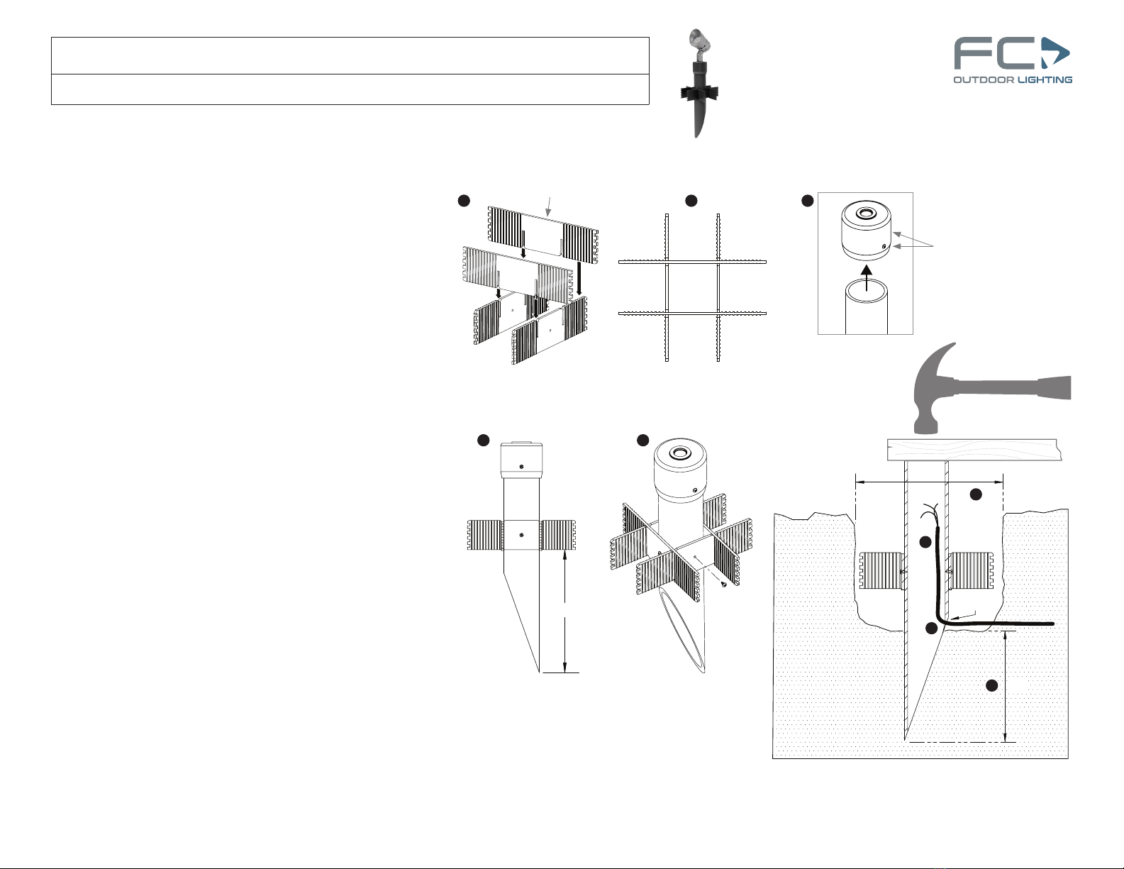
1) Remove the contents from inside the Ground Stake. Conrm that there are four “Fins” and four Screws.
2) Assemble the Fins of the Stabilizer Grid by mating them together using the two slots in each Fin. Fig. 1
3) Once the Stabilizer Grid is assembled it should look like this from the top view. Fig. 2
4) Slide the Stake in through the middle square of the Fin assembly Grid.
5) Secure the Fins to the Stake by screwing the (4) supplied Screws directly into the side of the Stake.
Note: Recommended Fin height is 10 inches from the bottom of the Stake. Fig. 3
6) Finished Ground Stake assembly. Fig. 4
7) Loosen Screw only and Remove the Top Mount Cap. Fig. 5 Set it aside for xture setup.
Installing Stake In Ground
8) Excavate for conduit lines and Stake post. Consider climate like snowfall conditions when determining
the post height above ground.
9) Dig a Hole where the Stake will be installed, approximately 10 inches in diameter and 8.25 inches
deep. Fig. 6 Stake should stand approximately 3 inches above ground. Silicone Wire Nuts and
Waterproof Junction Box should be used for wiring connections.
10) Feed the Lead Wire from the J-box up through the Ground Stake tube and tuck the excess wire back
in the top of the tube. Fig. 7
IMPORTANT: Feed wire from bottom as indicated to utilize Smooth Edge Wire Entry. Fig. 8
11) Position the Ground Stake in the center of the excavated hole and, if needed, place a at 2"x 4" piece
of wood or equivalent on top of the Stake tube and tap on it level to sink the post 7.5 inches into the
ground. Fig. 9
Continue next page ...

RG-DM-080423
CONFIDENTIAL THIS DOCUMENT IS THE PROPRIETARY PROPERTY OF FC LIGHTING, INC. ANY UNAUTHORIZED TRANSFER, USE OR REPRODUCTION IS STRICTLY PROHIBITED. ©2023 FC LIGHTING, INC.
corporate
t800.900.1730
3609 Swenson Ave.
St. Charles, IL 60174
FCF1103 (Heavy Duty Ground Stake HGS) - INSTALLATION INSTRUCTIONS
CAUTION: BEFORE CONNECTING THE FIXTURE TO A POWER SUPPLY, MAKE SURE THE POWER IS SWITCHED OFF.
DETAILED ILLUSTRATION
Includes: FCF1103 only.
2
GENERAL:
1. Before starting the installation, make sure all electricity has been turned off
and electrical breaker has been locked out and tagged out.
2. To ensure the success of the installation, be sure to read these instructions
and review the diagrams thoroughly before beginning.
3. All electrical connections must be in accordance with local codes, ordinances,
or the National Electrical Code.
4. This product must be installed in accordance with national and local electrical and
construction codes by a person familiar with the construction and operation of the
product and the hazards involved. Failure to comply with the following instructions
may result in injury or death.
NOTE: The important safeguards and instructions appearing in this
document are not meant to cover all possible conditions, equipment
and situations that may occur.
WARNING:
• Disconnect power to avoid electrical shock.
• Do not exceed xture specied voltage.
• Do not use if any parts are damaged.
• Unauthorized eld repair will void warranty.
• Retain all gaskets and hardware for reuse.
NOTE: LEDs are integral and NOT intended for general servicing.
Install Continued ...
NOTE: Once the Ground Stake (HGS) is in position you can backll around the post
with gravel for added stability, and add dirt at the surface. Fig 10
12) Loosen the Cord Grip on the xture Mounting Bracket, pass the Wiring through
the Mounting Cap, then torque the bottom nut on the Cord Grip onto the
Mounting Cap to 8 lbf-in (.66lb-ft) [.90 N-m]. Fig 11
13) Complete the wiring connections from the Fixture to the Lead Wires inside the
Stake tube using Silicone Wire Nuts.
14) Place the Mounting Cap over the Ground Stake, push the Cap down ush and
tighten in place using the philips head Set Screw provided. Fig 12
15) Set the Swivel Light Adjustment to desired position and tighten in place. Fig 13
16) To adjust the Vertical Light Direction loosen the center M6 5mm Drive Hex Head
Screw on the Mounting Bracket assembly, once adjusted to the desired position
torque the screw to 15 lbf-in (1.25 lbf-ft) [1.69 N-m]. Fig 14
17) Illustration of complete installation. Fig 15
18) Apply power to xture and test for proper operation.
Mounting
Cap
Set Screw
Mounting
Bracket
Cord
Grip
Knuckle
Vertical Light
Adjustment
Fixture
Swivel Light
Adjustment
Add Stone and Gravel
at Base for Stability
Fixture
Wire
Ground
Stake
11
10
13
12 14
15
RG-DM-080423
CONFIDENTIAL THIS DOCUMENT IS THE PROPRIETARY PROPERTY OF FC LIGHTING, INC. ANY UNAUTHORIZED TRANSFER, USE OR REPRODUCTION IS STRICTLY PROHIBITED. ©2023 FC LIGHTING, INC.
corporate
t800.900.1730
3609 Swenson Ave.
St. Charles, IL 60174
FCF1103 (Ground Stake GS) - INSTALLATION INSTRUCTIONS
CAUTION: BEFORE CONNECTING THE FIXTURE TO A POWER SUPPLY, MAKE SURE THE POWER IS SWITCHED OFF.
DETAILED ILLUSTRATION
Includes: FCF1103 only.
GENERAL:
1. Before starting the installation, make sure all electricity has been
turned off and electrical breaker has been locked out and tagged out.
2. To ensure the success of the installation, be sure to read these
instructions and review the diagrams thoroughly before beginning.
3. All electrical connections must be in accordance with local codes,
ordinances, or the National Electrical Code.
NOTE: The important safeguards and instructions appearing in this
manual are not meant to cover all possible conditions and situations
that may occur.
INSTALLATION INSTRUCTIONS:
NOTE: LED lamping is integral and NOT intended for general servicing.
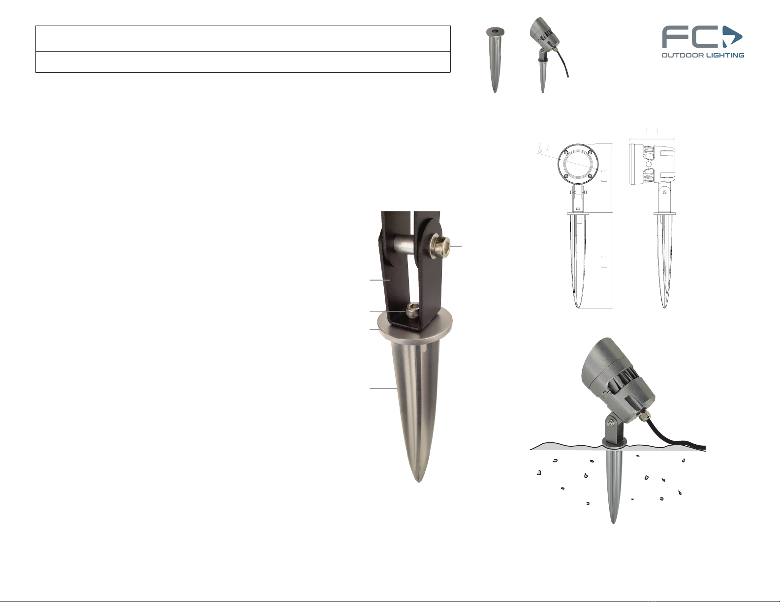
1) The Standard Mounting Bracket that comes with the FCF1103 can
be used to attach the xture to the Ground Stake using the supplied
Hex Bolt.
2) Once the xture is attached to the Ground Stake, make sure the
Adjustment Screw is tight before attempting to push the Stake into
the ground.
3) Pinpoint the position on the ground to install the xture. Grasp the
xture with one hand around the Mounting Bracket and one hand
rmly on top of the xture. Press the Stake into the ground until the
Stake Top is ush with the ground surface. Fig. A
4) Complete wiring connections to add power to the xture, following
NEC and local codes.
5) Test xtures to make sure they’re properly powered.
6) Loosen the M6 5mm Drive Adjustment Screw to tilt the xture and
aim the light to the desired height. Then torque to 15 lbf-in (1.25
lbf-ft) [1.69 N-m]. Loosen the 4mm Drive Hex Bolt to pivot the
xture and change the light direction. Then torque to 15 lbf-in (1.25
lbf-ft) [1.69 N-m].
7) If you need to remove a xture to relocate it, rst loosen the ground
around the Stake, gently remove the xture and stake, then repeat
step 3 above to reinstall the xture.
Ground Surface
Cord
Fixture
Fig. A
Hex Bolt
Stake Top
Standard
Mounting Bracket
Adjustment Screw
Ground Stake
Fixture Bracket &
Ground Stake Assembly
3.74
95
3.3
85
7.87
200
5.71
145
3.74
95
3.3
85
7.87
200
5.71
145
3
Table of contents
Other FC LIGHTING Outdoor Light manuals


