FCI DUBOX HT-2234 User manual

FCI USA, Inc. Manual P/N 10123594-9090
Issued: Date (12/20/2012) Page 1of 9
Revision 3
DUBOXTM
LOOSE PIECE HAND TOOL
Hand Tool Part Number
HT-2234 22 - 30 AWG
For termination Of DuboxTM 76357-x01LF Terminals
FCI MANUAL P/N 10123594-9090

FCI USA, Inc. Manual P/N 10123594-9090
Issued: Date (12/20/2012) Page 2of 9
Revision 3
HT-2234 HAND TOOL

FCI USA, Inc. Manual P/N 10123594-9090
Issued: Date (12/20/2012) Page 3of 9
Revision 3
Table of Contents
HAND TOOL ILLUSTRATION........................................................................................................2
TABLE OF CONTENTS ...................................................................................................................3
INTRODUCTION .............................................................................................................................4
SCOPE OF MANUAL......................................................................................................................4
HAND TOOL FEATURES ...............................................................................................................4
SPECIFICATIONS ..........................................................................................................................5
CRIMP SPECIFICATIONS...............................................................................................................5
SAFETY PRECAUTIONS................................................................................................................5
SETTING UP THE HAND TOOL .....................................................................................................5
ATTACHING THE TOOL HEAD .....................................................................................................5
CRIMPING PROCEEDURES ...........................................................................................................7
LOADING THE DUBOXTM TERMINAL ...................................................................................................... 7
CRIMPING PROCESS.................................................................................................................................... 8
TERMINAL HOLDER ADJUSTMENT ............................................................................................9
ALIGNMENT..................................................................................................................................................... 9
ROUTINE MAINTENANCE.............................................................................................................9
PARTS REPLACEMENT .................................................................................................................9
REFERENCE DRAWINGS
TA-317
REFERENCE DOCUMENTS
FORM #E-3245 - -Customer Application Machine Warranty and Service Policy
“Section I” Equipment owned by FCI USA LLC.
FORM #E-3244 - -Customer Application Machine Warranty and Service Policy
“Section II” Equipment purchased by the customer.
FORM # E-3247- - FCI Electronics Address List
Data herein have been verified and validated and are believed adequate for the intended use of the applicator. If the
applicator or procedures are used for purposes over and above the capabilities specified herein, confirmation of their
validity and suitability should be obtained; otherwise, FCI USA LLC does not guarantee results and assumes no
obligation or liability. This publication is not a license to operate under, nor a recommendation to infringe upon, any
process patents.

FCI USA, Inc. Manual P/N 10123594-9090
Issued: Date (12/20/2012) Page 4of 9
Revision 3
INTRODUCTION
SCOPE OF MANUAL:
This manual contains the information necessary to understand, install, operate and maintain the HT-2234
DuboxTM hand tools. This information is intended for the use by both the operator and service personnel.
However, certain procedures within the manual should be performed by service personnel only. These
procedures are identified by a warning instruction.
Refer to the table of contents for a breakdown of each subject matter covered in each section.
WARNINGS, CAUTIONS, and NOTES within the text of this manual are used to emphasize
important and critical instructions.
WARNING: An operating procedure, practice, etc. which if not carefully followed,
could result in personal injury, or affect the operator’s health.
CAUTION: An operating procedure, practice, etc. which, if not strictly observed,
could result in damage of equipment.
NOTE: An operating procedure, condition, etc. which it is essential to highlight.
We recommend that the operators and service personnel responsible for maintenance of the FCI hand tools
become thoroughly familiar with all aspects of the hand tool construction and operation. If operational or
maintenance problems arise which are beyond the scope of this manual, contact your district service
representative.
HAND TOOL FEATURES:
The HT-2234: Designed to terminate a single 22 –30 awg pre-stripped discrete wire to a loose-piece 22 –30
awg DuboxTM terminal, P/N 76357-x01LF. Two sets of crimp tooling are provided: One set is used to terminate
22 –24 awg wires while the other is utilized to terminate 26 - 30 awg wires. Labeling above each set of crimp
tooling indicates the appropriate wire range for that location.
The HT-2234 hand tool used to ergonomically terminate 1 crimp per cycle without lengthy set-up times.
A terminal holder is provided with two cavities that correspond to the conductor size being terminated.
Ratcheting handle ensures the complete crimping process has been fully completed and can be released
if required.
Spring-loaded wire-stops are installed on each tooling cavity to assist with correct wire placement.
The tool head can be easily separated from the handles for cleaning and tool maintenance.
FCI USA, Inc. Manual P/N 10123594-9090
Issued: Date (12/20/2012) Page 5of 9
Revision 3
SPECIFICATIONS:
Length … … … … … … … … … … … … … … … … … … … … … … … 197.5 mm ( 7.78”)
Width … … … … … … … … … … … … … … … … … … … … … … … 65.2 mm ( 2.57”)
Height … … … … … … … … … … … … … … … … … … … … … … … 145.5 mm (5.72”)
Weight … … … … … … … … … … … … … … … … … … … … … … … 240 grams (.53 lbs)
Color … … … … … … … … … … … … … … … … … … … … … … … .. Black with Blue Handles
CRIMP SPECIFICATIONS: Refer to FCI application specification “TA-317”
SAFETY PRECAUTIONS:
CAUTION: Verify that the hand tool is free of any debris, such as wire strands and that it manually operates
correctly.
CAUTION: This tool is designed to be operated by hand. Never install the HT-2234 hand tool in an air or
pneumatic assisted device as damage to the tool and increased safety concerns will result.
CAUTION: It is suggested to wear lightweight gloves when handling hand tools and terminals.
SETTING UP THE HAND TOOL:
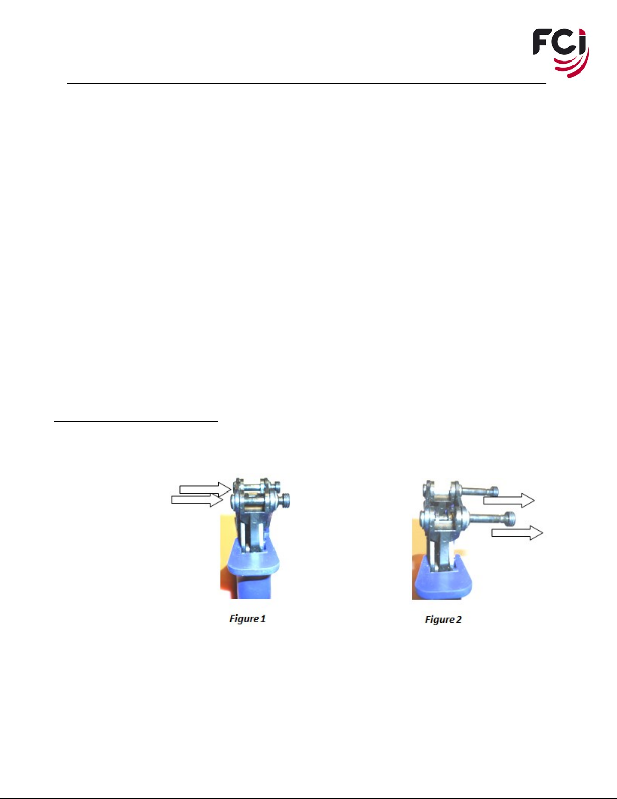
ATTACHING THE TOOL HEAD:
1. Push on both attachment pins from the front to disengage the locking feature of the pins, as shown in
Figure 1 above. Turn the tool around and manually pull out on each of the pin heads to fully retract the
pins until each pin locks into the retracted position, as shown in Figure 2 above.
FCI USA, Inc. Manual P/N 10123594-9090
Issued: Date (12/20/2012) Page 6of 9
Revision 3
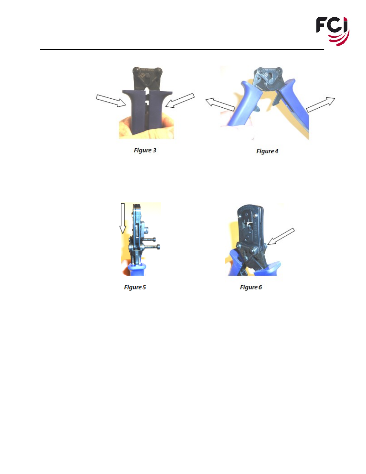
2. Fully close the handles until the ratchet mechanism releases to allow opening of the handle assembly, as
shown in Figure 3 above. Fully open the previously released handle assembly, as shown in Figure 4
above.
3. Position the crimp tooling assembly and insert this assembly into the handle cavity, as shown in Figure
5above. Following the example provided in Figure 6 above, align the mounting pin holes of the crimp
tooling assembly with those of the attachment pins and fully insert each of the two (2) pins until each of
the pins have passed through the crimp tooling assembly and handle, locking into the closed position.
Following this step, the heads of each of the two (2) pins will once again be fully seated against the
frame of the handle and locked into the closed position.
Note: The crimp tooling assembly will install and function correctly when the head is reversed
from the steps covered above.
4. Without a terminal or wire in place, dry cycle the assembled tool to verify the tooling is free to fully
close and open.

FCI USA, Inc. Manual P/N 10123594-9090
Issued: Date (12/20/2012) Page 7of 9
Revision 3
CRIMPING PROCEEDURES:
LOADING THE DUBOXTM TERMINAL:
Figure 6 Figure 7
1. Verify that the crimp tool is open. If not, manually close the handle, as shown in Figure6 above, until
you observe the last ‘click’. Release of the levers as illustrated in Figure 7 will allow the crimping
die(s) to open automatically.
2. Rotate the locator outward and down to its ‘load position’, as shown in Figure 8. Insert the DuboxTM
contact into the required cavity with the crimp features facing away from the tool (outward), as shown
in Figure 9 above for 22 –24 awg conductors. Rotate the locator upward until the locator comes to a
hard stop and is held in place with the magnet feature, as show above in Figure 10.
Note: This is only possible when the crimping die is in the fully open position.

FCI USA, Inc. Manual P/N 10123594-9090
Issued: Date (12/20/2012) Page 8of 9
Revision 3
CRIMPING PROCESS:
1. Close the hand tool till you observe the first ‘click’ of the ratchet, as indicated in Figure 11 above.
Using the correct wire gauge for the selected tooling cavity, insert the stripped wire into the slot of the
appropriate wire stop until the insulation makes contact with the wire stop, as shown in Figure 12.
Note: To determine the striping length, please refer to the application specification for the
DuboxTM terminal, TA-317.
2. While continuing to lightly hold the wire in position against the wire stop, close the levers as shown in
Figure 13 until the levers are fully closed and the ratchet makes the final “click”, releasing the hand
levers (handles) and die set to open as shown above in Figure 14.
FCI USA, Inc. Manual P/N 10123594-9090
Issued: Date (12/20/2012) Page 9of 9
Revision 3
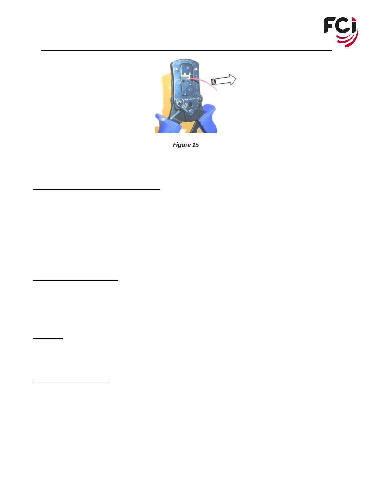
3. Remove the terminated contact by pulling the terminated wire straight from the hand tool.
TERMINAL HOLDER ADJUSTMENT(S):
TERMINAL HOLDER ALIGNMENT(S): The terminal holder assembly is designed to locate a loose-piece DuboxTM
terminal within the tooling to obtain a satisfactory termination form. When the terminal holder is fully closed, a magnet
stops against a setscrew to position the terminal over the anvils and obtain the optimal crimp form. Slight adjustment of
1/16th of a turn either clockwise or counter-clockwise to the installed setscrew with a 1.5mm Allen wrench will alter the
configuration of both the front and rear bellmouths.
NOTE: Terminate a sample and review before making additional adjustment(s).
ROUTINE MAINTENANCE
1. Use of a small brush and vacuum are the preferred methods to keep the hand tool clean of debris and
should be performed each shift, or sooner if necessary.
2. Lightly lubricate the top tooling and handle assemblies on a monthly schedule with light weight oil.
SERVICE
For service or technical help please call the FCI USA, Inc. service line at 1-800-843-6911.
PARTS REPLACEMENT
For spare part orders please call your FCI USA LLC distributor. Additionally, call1-800-222-2194 and ask for
CUSTOMER SERVICE. Please have part number(s) ready for the customer service person.
Table of contents
Other FCI Power Tools manuals


