Staubli MA251 User manual

1 / 12
PV-CZM...
* UL le E343181
MA251 (it_en)
Istruzioni d‘uso
MA251 (it_en)
Operating instructions
Pinza per crimpare PV-CZM...
per MC3, MC4 e MC4-EVO 2
Crimping pliers PV-CZM...
for MC3, MC4 and MC4-EVO 2
Indice
Istruzioni per la sicurezza������������������������������������������������������������2
Versione per MC3����������������������������������������������������������������������3
Versione per MC4����������������������������������������������������������������������4
Versione per MC4-EVO 2�����������������������������������������������������������5
Sostituire l‘inserto di crimpatura �����������������������������������������������7
— Asportazione dell‘inserto di crimpatura ���������������������������������7
— Inserimento dell‘inserto di crimpatura �����������������������������������7
Crimpatura���������������������������������������������������������������������������������8
Qualità della crimpatura�������������������������������������������������������������9
Note������������������������������������������������������������������������������������10-12
Content
Safety Instructions����������������������������������������������������������������������2
Explanation for MC3������������������������������������������������������������������3
Explanation for MC4������������������������������������������������������������������4
Explanation for MC4-EVO 2 ������������������������������������������������������ 5
Exchanging the crimping insert�������������������������������������������������7
— Removing the crimping insert������������������������������������������������7
— Fitting the crimping insert������������������������������������������������������7
Crimping������������������������������������������������������������������������������������8
Crimping quality ������������������������������������������������������������������������9
Notes ����������������������������������������������������������������������������������10-12

2 / 12
Istruzioni per la sicurezza Safety Instructions
I prodotti possono essere montati e installati solo da esperti
qualicati e formati, rispettando tutte le disposizioni di sicurez-
za e le norme di legge applicabili.
Stäubli Electrical Connectors (Stäubli) declina qualsiasi re-
sponsabilità derivante dal mancato rispetto delle presenti av-
vertenze.
The products may be assembled and installed exclusively by
suitably qualied and trained specialists duly observing all ap-
plicable safety regulations.
Stäubli Electrical Connectors (Stäubli) does not accept any li-
ability in the event of failure to observe these warnings.
Utilizzare esclusivamente i pezzi e gli attrezzi indicati da Stäu-
bli. Rispettare sempre le procedure qui descritte per la prepa-
razione e il montaggio, poiché in caso contrario non potranno
essere garantiti né la sicurezza né il rispetto delle caratteristi-
che tecniche indicate. Non apportare in nessun modo modi-
che al prodotto.
Use only the components and tools specied by Stäubli. In
case of self-assembly, do not deviate from the preparation
and assembly instructions as stated herein, otherwise Stäubli
cannot give any guarantee as to safety or conformity with the
technical data. Do not modify the product in any way.
I lavori qui descritti non possono essere eseguiti su
pezzi sotto tensione o corrente.
The work described here must not be carried out
on live or load-carrying parts.
La protezione da scosse elettriche deve essere ga-
rantita nel prodotto nale e accertata dall’utente.
Protection from electric shock must be assured by
the end product (i.e. by the correctly assembled
plug connector) and by its user.
Stäubli consiglia di non utilizzare né cavi in PVC né
cavi non stagnati del tipo H07RN-F.
For safety reasons, Stäubli does strongly recom-
mend not to use PVC cables or untinned cables of
type H07RN-F.
Ulteriori caratteristiche tecniche sono indicate nel
catalogo del prodotto.
For further technical data please see the product
catalogue.
Spiegazione dei simboli Explanation of the symbols
Pericolo! Voltaggi pericolosi Warning of dangerous voltages
Pericolo! Area pericolosa Warning of a hazard area
Consiglio utile Useful hint or tip

3 / 12
1
2
3
45
4
Pos. Sezione del cavo
Cable cross section
adatto a
suitable for
mm2AWG
4410 PV-SP3/4
PV-BP3/4
510 PV-SP4/10
PV-BP4/10
Pos. Sezione del cavo
Cable cross section
adatto a
suitable for
mm2AWG
12,5 14 PV-SP3/4
PV-BP3/4
2412 PV-SP3/4
PV-BP3/4
36PV-SP3/6
PV-BP3/6
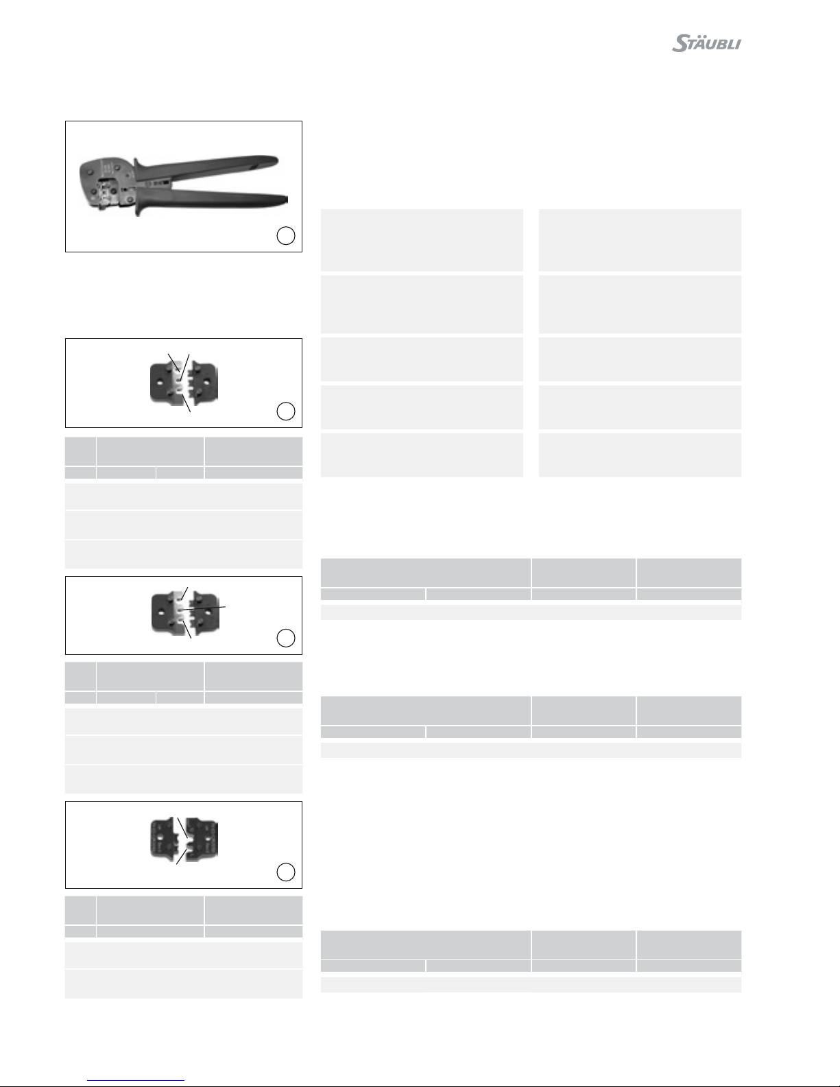
Versione per MC3 Explanation for MC3
(ill. 1)
Pinza per crimpare PV-CZM-16100A
inclusi due locatori e due inserti di
crimpatura
(ill. 1)
Crimping pliers PV-CZM-16100A
incl. two interchangeable Locators
and two interchangeable crimping
inserts
Sezione del cavo: 2,5 / 4 / 6mm2
(14 / 12 / 10AWG)
N° di codice: 32.6020-16100A
Crimping range: 2,5 / 4 / 6mm2
(14 / 12 / 10AWG)
Order No.: 32.6020-16100A
Parti sciolte Individual parts
(ill. 2 + 3)
Inserti di crimpatura intercambiabili
(ill. 2 + 3)
Interchangeable crimping inserts
Raggio di crimpatura
Crimping range
Tipo
Type
N° di codice.
Order No.
mm2AWG
2,5 / 4 / 6 14 / 12 / 10 PV-ES-CZM-16100 32.6021-16100
4 / 10 PV-ES-CZM-17100 32.6021-17100
(ill. 4)
Locatori intercambiabili
(ill. 4)
Interchangeable locators
Raggio di crimpatura
Crimping range
Tipo
Type
N° di codice.
Order No.
mm2AWG
2,5 / 4 / 6 12 / 10 PV-LOC-A 32.6039
4 / 10 PV-LOC-A10 32.6049
Questo tipo di locatori sono solo per
Ø 3mm
This locator types are for Ø 3mm only
4 / 12
5
12
3
5
4
6
8
7
6
7
8
Versione per MC4 Explanation for MC4
(ill. 5)
Pinze di crimpatura incluso locato-
re PV-LOC e inserto di crimpatura
integrato
(ill. 5)
Crimping pliers incl. locator PV-LOC
and built-in crimping insert
Raggio di crimpatura: 1,5 / 2,5 / 4mm2
(14 / 12AWG)
Tipo: PV-CZM-18100
N° di codice: 32.6020-18100
Crimping range: 1,5 / 2,5 / 4mm2
(14 / 12AWG)
Type: PV-CZM-18100
Order No.: 32.6020-18100
Raggio di crimpatura: 2,5 / 4 / 6mm2
(12 / 10AWG)
Tipo: PV-CZM-19100
N° di codice: 32.6020-19100
Crimping range: 2,5 / 4 / 6mm2
(12 / 10AWG)
Type: PV-CZM-19100
Order No.: 32.6020-19100
Raggio di crimpatura: 4 / 10mm2
Tipo: PV-CZM-20100
N° di codice: 32.6020-20100
Crimping range: 4 / 10mm2
Type: PV-CZM-20100
Order No.: 32.6020-20100
Raggio di crimpatura: 6 / 10mm2
Tipo: PV-CZM-21100
N° di codice: 32.6020-21100
Crimping range: 6 / 10mm2
Type: PV-CZM-21100
Order No.: 32.6020-20100
Raggio di crimpatura: 8 / 12 / 10AWG
Tipo: PV-CZM-22100
N° di codice: 32.6020-22100
Crimping range: 8 / 12 / 10AWG
Type: PV-CZM-22100
Order No.: 32.6020-22100
Parti sciolte Individual parts
(ill. 6 + 7 + 8 + 9 + 10)
Inserti di crimpatura intercambiabili
(ill. 6 + 7 + 8 + 9 + 10)
Interchangeable crimping inserts
Raggio di crimpatura
Crimping range
Tipo
Type
N° di codice
Order No.
mm2AWG
1,5 / 2,5 / 4 14 / 12 PV-ES-CZM-18100 32.6021-18100
Raggio di crimpatura
Crimping range
Tipo
Type
N° di codice
Order No.
mm2AWG
2,5 / 4 / 6 12 / 10 PV-ES-CZM-19100 32.6021-19100
Raggio di crimpatura
Crimping range
Tipo
Type
N° di codice
Order No.
mm2AWG
4 / 10 PV-ES-CZM-20100 32.6021-20100
Pos. Sezione del cavo
Cable cross section
adatto a
suitable for
mm2AWG
11,5 14 PV-SP4/2.5
PV-BP4/2.5
22,5 PV-SP4/2.5
PV-BP4/2.5
3412 PV-SP4/6
PV-BP4/6
Pos. Sezione del cavo
Cable cross section
adatto a
suitable for
mm2AWG
42,5 PV-SP4/2.5
PV-BP4/2.5
5412 PV-SP4/6
PV-BP4/6
66 10 PV-SP4/6
PV-BP4/6
Pos. Sezione del cavo
Cable cross section
adatto a
suitable for
mm2
74PV-SP4/6
PV-BP4/6
810 PV-SP4/10
PV-BP4/10
5 / 12
9
10
9
11
11
12
13 10
12
Raggio di crimpatura
Crimping range
Tipo
Type
N° di codice
Order No.
mm2
6 / 10 PV-ES-CZM-21100 32.6021-21100
Raggio di crimpatura
Crimping range
Tipo
Type
N° di codice
Order No.
AWG
8 / 12 / 10 PV-CZM-22100 32.6020-22100
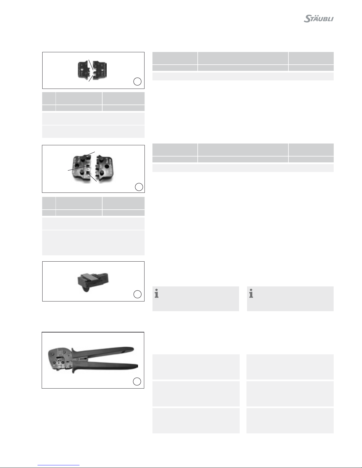
(ill. 11)
Locatore PV-LOC
N° di codice: 32.6040
Locatore PV-LOC-B
N° di codice: 32.6055
Avvertenza:
Quando si utilizza la pinza
PV-CZM-22100, si prega di utiliz-
zare la matrice PV-LOC-B�
(ill. 11)
Locator PV-LOC
Order No.: 32.6040
Locator PV-LOC-B
Order No.: 32.6055
Note:
When using the crimping tool
PV-CZM-22100, please use the
locator PV-LOC-B�
Versione per MC4-EVO 2 Explanation for MC4-EVO 2
(ill. 12)
Pinze di crimpatura incluso locatore e
inserto di crimpatura integrato
(ill. 12)
Crimping pliers incl. Locator and built
in crimping insert
Raggio di crimpatura: 1,5 / 2,5 / 4mm2
(14 / 12AWG)
Tipo: PV-CZM-40100
N° di codice: 32.6020-40100
Crimping range: 1,5 / 2,5 / 4mm2
(14 / 12AWG)
Type: PV-CZM-40100
Order No.: 32.6020-40100
Raggio di crimpatura: 2,5 / 4 / 6mm2
(14 / 12 / 10AWG)
Tipo: PV-CZM-41100
N° di codice: 32.6020-41100
Crimping range: 2,5 / 4 / 6mm2
(14 / 12 / 10AWG)
Type: PV-CZM-41100
Order No.: 32.6020-41100
Raggio di crimpatura: 4 / 10mm2
(12 / 8AWG)
Tipo: PV-CZM-42100
N° di codice: 32.6020-42100
Crimping range: 4 / 10mm2
(12 / 8AWG)
Type: PV-CZM-42100
Order No.: 32.6020-42100
Pos. Sezione del cavo
Cable cross section
adatto a
suitable for
mm2
96PV-SP4/6
PV-BP4/6
10 10 PV-SP4/10
PV-BP4/10
Pos. Sezione del cavo
Cable cross section
adatto a
suitable for
AWG
11 8PV-SP4/8
PV-BP4/8
12 10 PV-SP4/6
PV-BP4/6
13 12 PV-SP4/6
PV-BP4/6

6 / 12
13
14
15
16
2
1
3
5
4
6
7
8
Parti sciolte Individual parts
(ill. 13 + 14 + 15)
Inserti di crimpatura intercam-
biabili
(ill. 13 + 14 + 15)
Interchangeable crimping inserts
Raggio di crimpatura
Crimping range
Tipo
Type
N° di codice
Order No.
mm2AWG
1,5 / 2,5 / 4 14 / 12 PV-ES-CZM-40100 32.6021-40100
Raggio di crimpatura
Crimping range
Tipo
Type
N° di codice
Order No.
mm2AWG
2,5 / 4 / 6 14 / 12 / 10 PV-ES-CZM-41100 32.6021-41100
Raggio di crimpatura
Crimping range
Tipo
Type
N° di codice
Order No.
mm2AWG
4 / 10 12 / 8 PV-ES-CZM-42100 32.6021-42100
(ill. 16)
Locatore PV-LOC-C
N° di codice: 32.6056
(ill. 16)
Locator PV-LOC-C
Order no.: 32.6056
Pos. Sezione del cavo
Cable cross section
adatto a
suitable for
mm2AWG
11,5 PV-SP4-EVO 2/2,5
PV-BP4-EVO 2/2,5
22,5 14 PV-SP4-EVO 2/2,5
PV-BP4-EVO 2/2,5
3412 PV-SP4-EVO 2/6
PV-BP4-EVO 2/6
Pos. Sezione del cavo
Cable cross section
adatto a
suitable for
mm2AWG
42,5 14 PV-SP4-EVO 2/2,5
PV-BP4-EVO 2/2,5
5412 PV-SP4-EVO 2/6
PV-BP4-EVO 2/6
66 10 PV-SP4-EVO 2/6
PV-BP4-EVO 2/6
Pos. Sezione del cavo
Cable cross section
adatto a
suitable for
mm2AWG
7412 PV-SP4-EVO 2/6
PV-BP4-EVO 2/6
810 8PV-SP4-EVO 2/10
PV-BP4-EVO 2/10
2
1
3
6
5
4
7
8
7 / 12
21
22
19
20
17
18
Sostituire l‘inserto di crimpa-
tura
Exchanging the crimping
inserts
Asportazione dell‘inserto di crim-
patura
Removing the crimping insert
(ill. 17)
Chiudere la pinza per crimpare.
(ill. 17)
Close the crimping tool
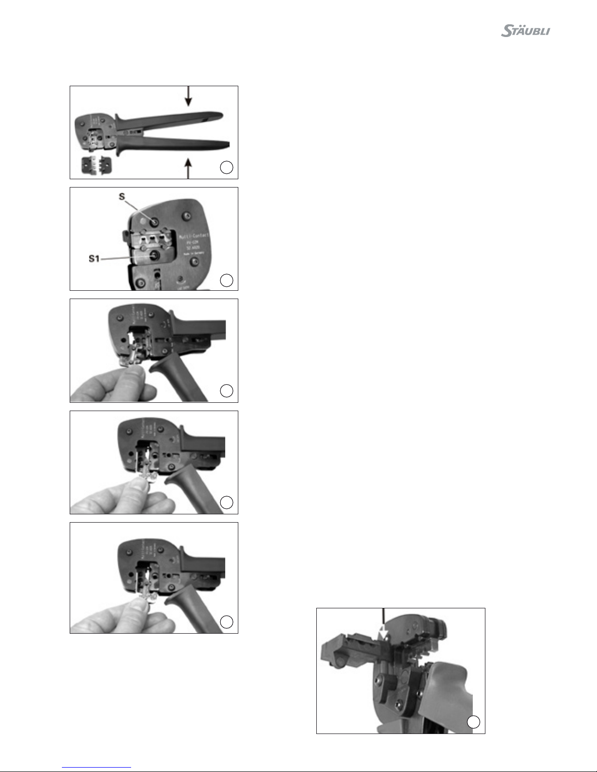
(ill. 18)
Svitare la vite lunga (S) e la vite corta
(S1) ed aprire la pinza per crimpare
(stringere a fondo e poi rilasciare).
(ill. 18)
Unscrew both the long S and the
short S1 screw. Open the crimping
tool (press completely together and
release).
(ill. 19)
Togliere l‘inserto di crimpatura supe-
riore.
(ill. 19)
Remove the upper crimping insert.
(ill. 20)
Togliere l‘inserto di crimpatura infe-
riore.
(ill. 20)
Remove the lower crimping insert.
Inserimento dell‘inserto di crim-
patura
Fitting the crimping insert
(ill. 21)
Aprire la pinza per crimpare (stringere
a fondo e poi rilasciare).
Inserire entrambi gli inserti di crim-
patura. Il contrassegno deve trovarsi
sullo stesso lato del contrassegno
presente sulla pinza per crimpare.
Chiudere la pinza per crimpare.
Stringere entrambe le viti degli stampi
di crimpatura.
(ill. 21)
Open the crimping tool (press com-
pletely together and release). Insert
both crimping inserts. The markings
must be on the same side as the
marking on the crimping tool.
Close crimping tool and screw both
crimping inserts tight.
(ill. 22)
Inserto locatore nel pin guida.
(ill. 22)
Insert locator into the guide pin.

8 / 12
25
26
23
24
(ill. 23)
Ruotare il locatore (trattenuto magne-
ticamente)
(ill. 23)
Rotate the locator (held magnetically)
(ill. 24)
Fissare il locatore.
(ill. 24)
Lock the locator.
Crimpatura Crimping
Esempio per ADBP3/... e ADSP3/... Example for ADBP3/... and
ADSP3/...
(ill. 25)
Rimuovere il locatore. Inserire il cavo
spellato nel lato sinistro nchè l’isola-
mento viene a contatto con l’inserto di
crimpatura.
Serrare la pinza completamente. Con-
trollare la crimpatura.
(ill. 25)
Remove the locator. Insert the
stripped cable on the left side until the
insulation comes into contact with the
crimping insert. Close crimping tool
completely.
Check crimp.
Esempio per KBT4.../KST4... Example for KBT4.../KST4...
(ill. 26)
Aprire e mantenere aperta la clip di
bloccaggio (K). Inserire il contatto nel
corretto inserto di crimpatura in base
alla sezione del cavo. Girare il contat-
to in modo da portare le linguette di
crimpatura in alto. Rilasciare la clip di
bloccaggio (K). Il contatto è ssato.
(ill. 26)
Open and hold clamping clip K. Insert
contact in the appropriate cross-sec-
tion range of the crimping tool. Turn
contact till crimping tabs face the top.
Release clamping clip K. The contact
is secured.

9 / 12
29
27
28
(ill. 27)
Stringere leggermente la pinza afn-
ché le linguette di crimpatura siano
posizionate saldamente all’interno
dell’inserto di crimpatura.
(ill. 27)
Lightly press the pliers together so
that the crimping tabs lie securely
within the crimping die.
(ill. 28)
Inserire il cavo spelato no a quando
la guaina isolante è a contatto con
l’inserto di crimpatura. Stringere com-
pletamente la pinza per crimpare.
(ill. 28)
Insert the stripped cable until the
insulation comes into contact with the
crimping insert. Close crimping tool
completely.
Qualità della crimpatura Crimping quality
La qualità della crimpatura può essere
valutata in base all’altezza della stessa.
Le dimensioni per i cavi FLEX-SOL-XL
e Studer BETAam® sono riportate
nella tabella seguente.
The quality of the crimp can be as-
sessed on the basis of the crimp
height. Typical values for the cables
FLEX-SOL-XL and Studer BETAam®
are shown in the following table.
(ill. 29)
Controllare la crimpatura.
(ill. 29)
Visually check the crimp.
MC4 / MC4-EVO 2 MC3
ACavo
Cable
Altezza della
crimpatura
Crimp height
mm2mm
1,5 FLEX-SOL-XL
BETAam®
1,65
1,65
2,5 FLEX-SOL-XL
BETAam®
1,80
1,80
4FLEX-SOL-XL
BETAam®
2,15
2,15
6FLEX-SOL-XL
BETAam®
2,40
2,40
10 FLEX-SOL-XL 3,02
ACavo
Cable
Altezza della
crimpatura
Crimp height
mm2mm
1,5 FLEX-SOL-XL
BETAam®
2,20
2,20
2,5 FLEX-SOL-XL
BETAam®
2,20
2,20
4FLEX-SOL-XL
BETAam®
2,50
2,50
6FLEX-SOL-XL
BETAam®
3,12
3,12
10 FLEX-SOL-XL 4,80

10 / 12
Note / Notes:

11 / 12
Note / Notes:

12 / 12
Fabbricante/Producer:
Stäubli Electrical Connectors AG
Stockbrunnenrain 8
4123 Allschwil/Switzerland
Tel. +41 61 306 55 55
Fax +41 61 306 55 56
www.staubli.com/electrical
© by Stäubli Electrical Connectors AG, Switzerland – MA251 – 01.2017, Index a, Marketing Communications – Salvo modiche / Subject to alterations
Note / Notes:
Other manuals for MA251
7
Table of contents
Other Staubli Power Tools manuals

Staubli
Staubli MA251 User manual

Staubli
Staubli MA251 User manual

Staubli
Staubli MA251 User manual

Staubli
Staubli MA251 User manual

Staubli
Staubli MA224 User manual

Staubli
Staubli MA251 User manual

Staubli
Staubli PV-AZM User manual

Staubli
Staubli M-PZ-T2600 User manual

Staubli
Staubli M-PZ13 User manual

Staubli
Staubli M-PZ13 User manual

Staubli
Staubli MA251 User manual

Staubli
Staubli CTD-M-CZ User manual

Staubli
Staubli M-PZ-T2600 User manual

Staubli
Staubli PV-MS-PLS User manual

Staubli
Staubli M-PZ13 User manual

Staubli
Staubli PV-MS-PLS User manual

Staubli
Staubli PV-MS-PLS User manual

Staubli
Staubli PV-CZM-BS User manual

Staubli
Staubli M-PZ-T2600 User manual


