MOUNTING
•On a 4-inch square box with or without
plaster ring. Minimum depth 1.5 inches.
•On a 3.5-inch octagonal box. Minimum depth
1.5 inches.
INSTALLATION
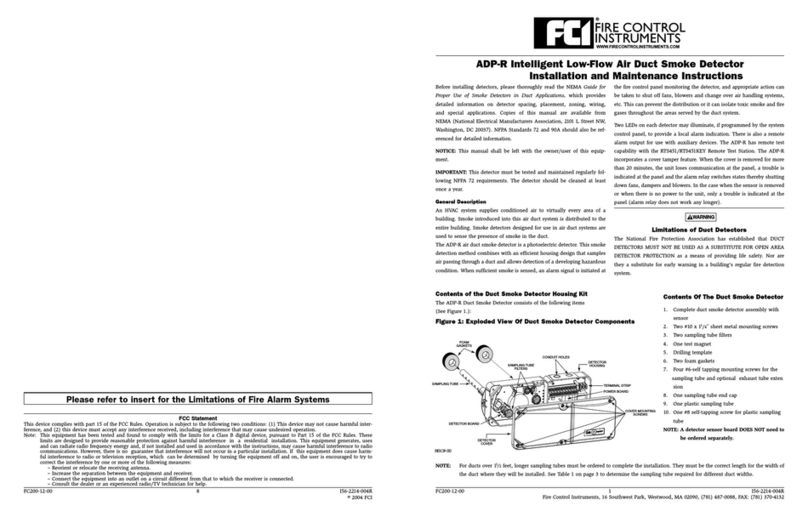
Place the detector into the detector base. Turn the de-
tector clockwise until the detector locks into place.
Tousethetamper-prooffeature, break the smaller tab
onthescribedlineinthetamperprooftablocatedonthe
detector mounting bracket. Install the detector. To re-
move the detector from the base when using the tam-
per-proof feature, insert the blade of a small
screwdriver into the hole on the side of the base and
pushtheplasticleverawayfromthedetector head. This
will allow the detector to be rotated counterclockwise
for removal. NOTE: The decorative ring must be re-
moved in order to removetheheadwhenusing the tam-
per-proof feature.
The tamper-proof feature may be defeated perma-
nently by breaking the plastic lever off the base.
NOTE: The number of two-wire smoke detectors
which can be accommodated per zone varies with dif-
ferent control panels. Consult the control panel in-
struction manual to determine the capacity.
RefertoNFPA72,Chapter5-3, “SmokeSensingFire
Detectors” for spacing, location of detectors and other
guidelines.
TESTING
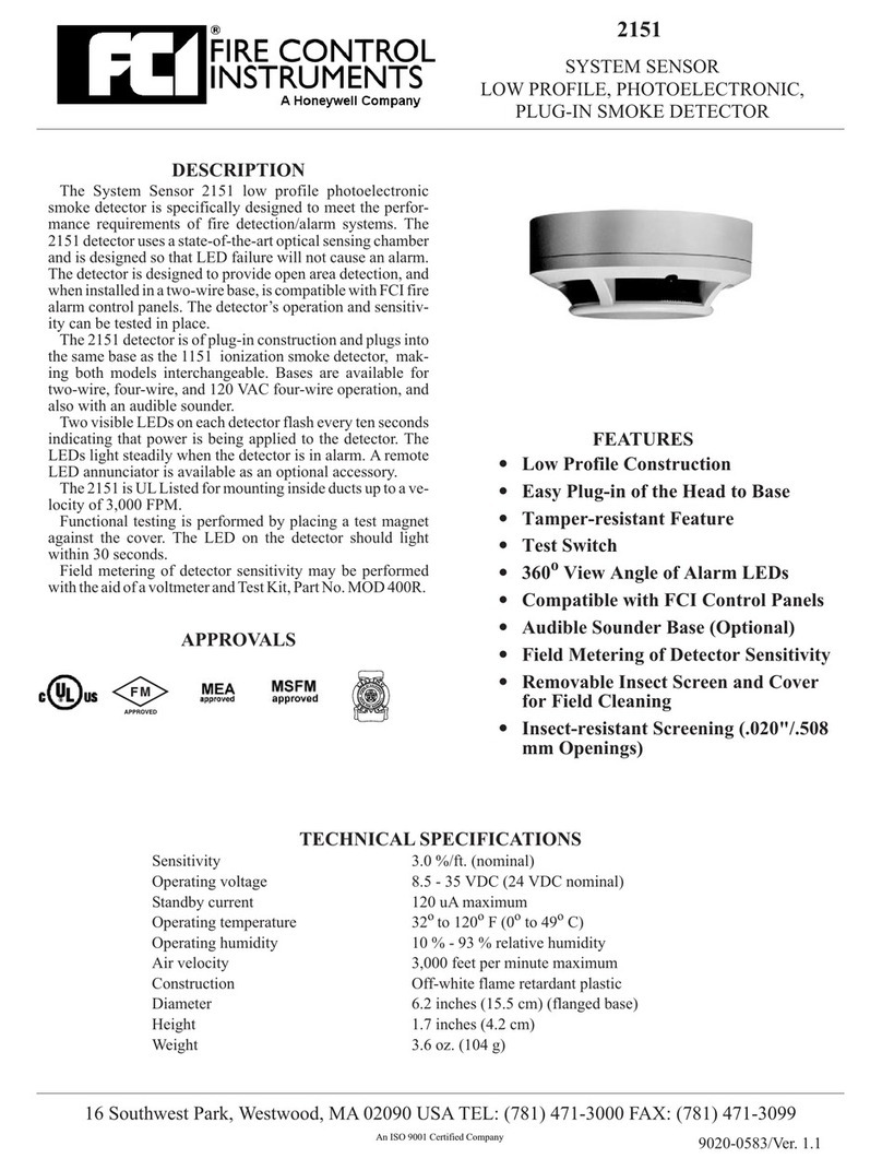
Detectors may be tested in the following ways:
•Place a test magnet against the detector as
directed in the installation instructions. The de-
tector should go into alarm within 30
seconds.
•Field metering of detector sensitivity may be
performed with the aid of a voltmeter and Test
Kit, P/N 119-9010N.
For the complete procedure, refer to the Installation
and Maintenance instructions furnished with each de-
tector.
MAINTENANCE
Cleaning programs should be adapted to the individ-
ual environment in conformance with NFPA Standard
72. We recommend at least an annual cleaning of the
unit. The detector screen and cover assembly can be re-
moved, revealing the sensing chamber. A vacuum
cleaner can be used to remove dust from the screen,
cover and sensing chamber. For the complete proce-
dure, refer to the Installation and Maintenance instruc-
tions furnished with each detector.
2 of 2 9020-0375
ORDERING AND TECHNICAL INFORMATION
Part No. Model Contacts Description
112-90001 301PL Photoelectronic Detector
110-90008 301BL Base, Two-wire
110-90009 301BL4 Form A & C Base, four-wire, 24 VDC operation
110-90010 301BL4AC Form A, C & Supv. Base, four-wire, 120 VAC operation
110-90014 B401BH Base, four-wire, with audible sounder
138-01005 RA-400Z Remote Alarm Indicator
119-63020 2040-24 Form B End of Line Relay, 24 VDC
119-9010N Test Kit
FIRE CONTROL INSTRUMENTS, Inc.
