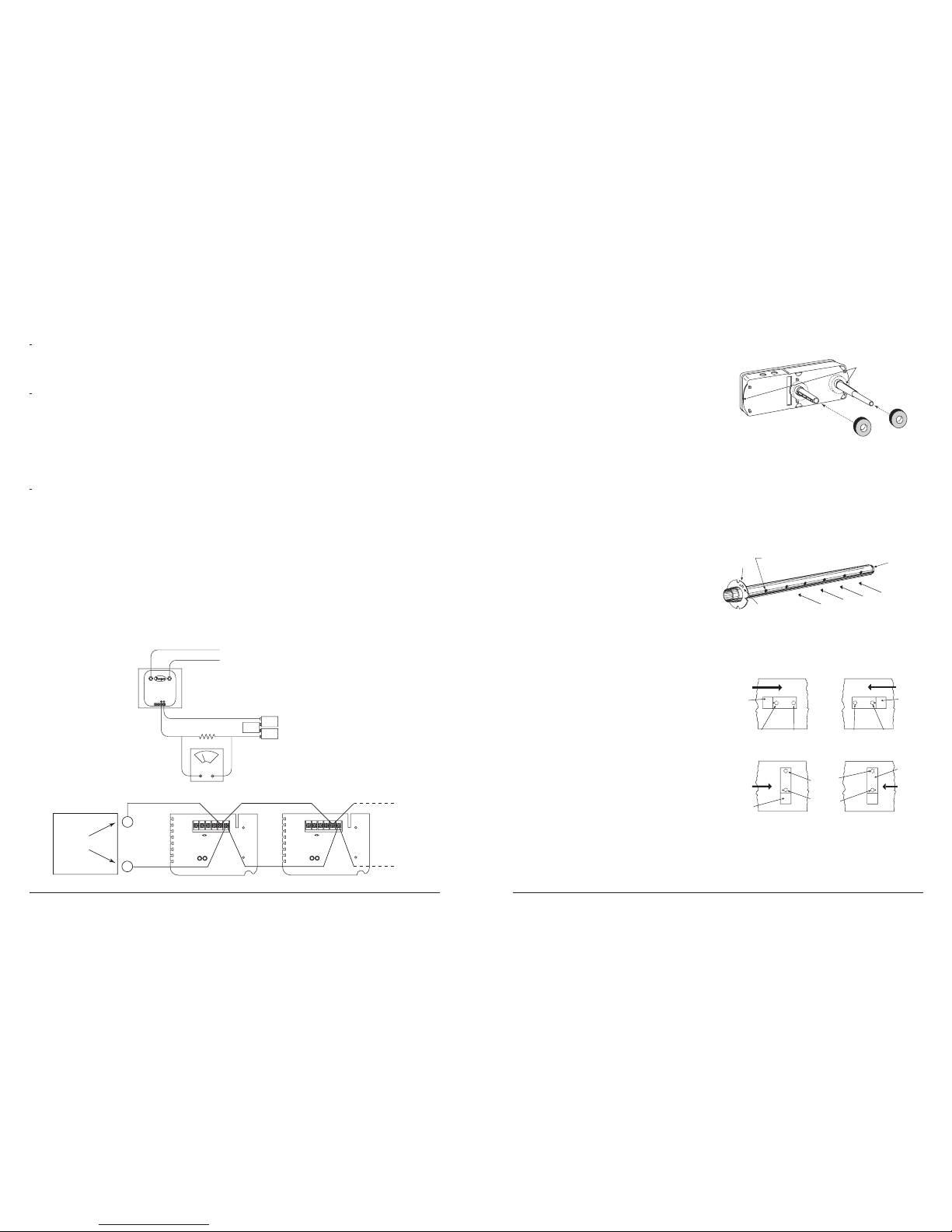
[4.2] Installation For Ducts More Than 8 Feet (2.4m) Wide
NOTE: To install sampling tubes in ducts more than 8 feet (2.4m) wide, work must be performed inside the air duct. Sampling of air in ducts wider
than 8 feet (2.4m) is accomplished by using the ST-10 sampling tube. If the tube is shorter than the width of the air duct, install the end cap
into the sampling tube as shown in Figure 4 and support the end opposite the duct smoke detector.
Install the sampling tube as follows:
1. Drill a 3⁄4-inch (19mm) hole in the duct directly opposite the hole already drilled for the sampling tube. Make sure the hole is 1″to 2″(25 to 50mm)
below the inlet hole on the opposite side of the duct to allow for moisture drainage.
2. Slide the sampling tube with the flange into the housing bushing that meets the air flow first. Position the tube so that the arrow points into the air
flow. Secure the tube flange to the housing bushing with two #6 self-tapping screws.
3. From inside the duct, couple the other sections of the sampling tube to the section already installed using the 1⁄2-inch (12mm) conduit fittings sup-
plied. Make sure that the holes on both of the sampling tubes are lined up and facing into the air flow.
4. Trim the end of the tube protruding through the duct so that 1″to 2″(25 to 50mm) of the tube extend outside the duct. Plug this end with the end
cap and tape closed any holes in the protruding section of the tube. Be sure to seal the duct where the tube protrudes.
NOTE: An alternate method to using the ST-10 is to use two ST-5 sampling tubes. Remove the flange from one of the tubes and install as described
above. After the installation, use electrical tape to close off some of the sampling holes so that there are a total of 10 to 12 holes spaced as
evenly as possible across the width of the duct.
NOTE: Air currents inside the duct may cause excessive vibration, especially when the longer sampling tubes are used. In these cases a 3 inch
(75mm) floor flange (available at most plumbing supply stores) may be used to fasten the sampling tube to the other side of the duct. When
using the flange/connector mounting technique, drill a 1-inch to 11⁄4-inch (25 to 32mm) hole where the flange will be used.
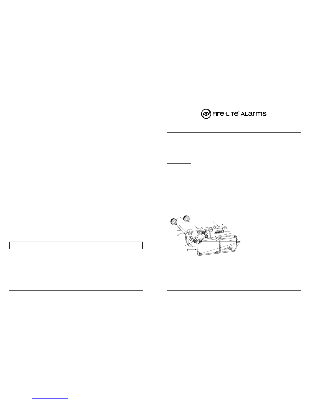
[5] Install The Filters
To install the sampling tube filters, simply push the filters into the sampling and exhaust tube holes, as shown in Figure 6. If a metal sampling tube is
used, install the filters over the tube end.
F300-27-00 4 I56-1975-003R
Figure 6. Sampling tube filter installation:
[6] Field Wiring Installation Guidelines
All wiring must be installed in compliance with the National Electrical
Code and the local codes having jurisdiction. Proper wire gauges should
be used. The conductors used to connect smoke detectors to control
panels and accessory devices should be color-coded to prevent wiring
mistakes. Improper connections can prevent a system from responding
properly in the event of a fire.
Filters require periodic cleaning or replacement, depending on the
amount of dust and dirt accumulated. Visually inspect the filters at
least quarterly; inspect them more often if the dust accumulation
warrants it. See Section [9.1.2] for more information. Replacement
filters can be ordered (filter P/N F36-09-11).
For signal wiring, (the wiring between detectors or from detectors to auxiliary devices), it is usually recommended that single conductor wire be no
smaller than 18 gauge. The duct smoke detector terminals accommodate wire sizes up to 12 gauge. The last foot of conduit should be flexible conduit
(available in electrical supply houses), which facilitates easier installation and puts less strain on the conduit holes in the housing. Solid conduit con-
nections may be used if desired.
Smoke detectors and alarm system control panels have specifications for Signaling-Line Circuit (SLC) wiring. Consult the control panel manufacturer’s
specifications for wiring requirements for the particular model control panel being used before wiring the detector loop.
The D350PL detector is designed for ease of wiring. The housing provides a terminal strip with clamping plates. Wiring connections are made by
stripping about 3⁄8-inch (9mm) of insulation from the end of the wire, sliding the bare end under the plate, and tightening the clamping plate screw.
Two LEDs on each duct smoke detector may light, if programmed by the system control panel, to provide a local, visible indication. Remote LED
annunciator capability is available as an option. Each duct smoke detector can only be wired to one remote accessory.
Fire•Lite panels offer different feature sets across different panel models. As a result, certain features of the D350PL may be available on some control
panels, but not on others. The possible features available in the D350PL, if supported by the control panel are:
1. Panel controls the LED operation on the duct smoke detector. Operational modes are RED blink, RED continuous, GREEN blink, GREEN continu-
ous, and off.
2. The remote output may be synchronized to the LED operation or controlled independent of the LEDs.
Please refer to the operation manual for the UL listed control panel for specific operation of the D350PL
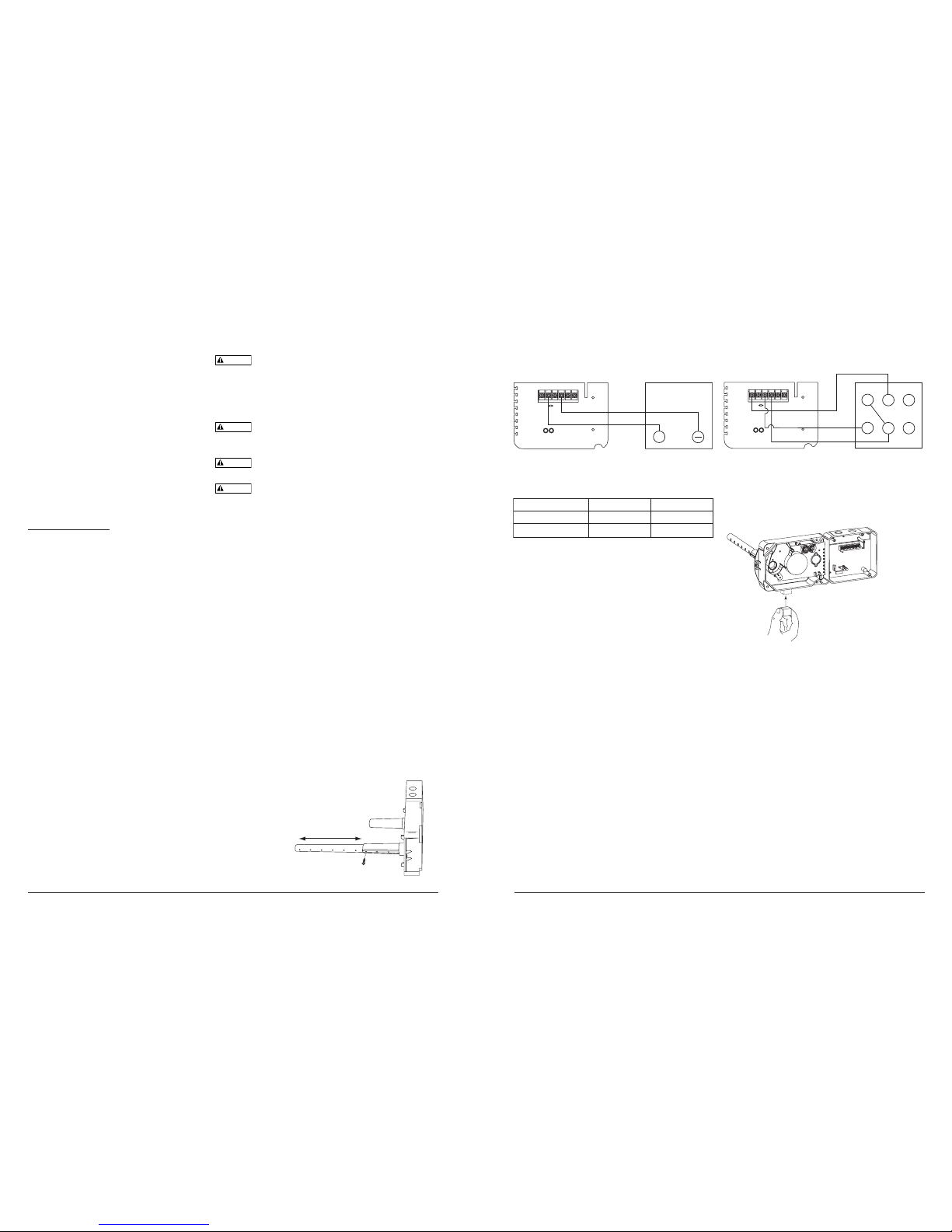
WIRING INSTRUCTIONS
Disconnect power from the communication line before installing the D350PL duct smoke detectors.
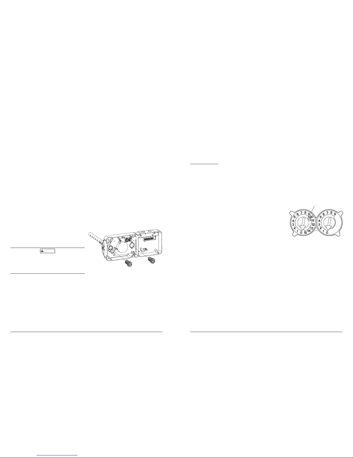
Wire the D350PL duct smoke detector per the Control Panel Installation Manual and Figures 9, 10 or 11. Set the desired address on the sensor board
code wheel address switches.
NOTE: Some panels support extended addressing. In order to set the sensor above address number 99 on compatible systems, carefully remove
the stop on the left hand rotary switch with pliers as shown in Figure 7.
[7] Perform Detector Check
1. Perform STANDBY AND TROUBLE TEST per Section [9.2.1].
2. Perform MAGNET TEST per Section [9.2.2.1]. The RTS451 test of Section [9.2.2.2] may substitute for this requirement.
3. Perform AIR FLOW TEST per Section [9.1].
4. Perform SMOKE RESPONSE TEST per Section [9.1.1].
[8] Install The Cover
Install the cover using the six screws that are captured in the housing cover. Be certain
filters are installed as specified in Section [5]. Make sure that the cover fits into the base
groove and that all gaskets are in their proper positions. Tighten the six screws.
[9] Duct Smoke Detector Maintenance and Test Procedures
Test and maintain duct smoke detectors as recommended in NFPA 72. The tests con-
tained in this manual were devised to assist maintenance personnel in verification of
proper detector operation.
Before conducting these tests, notify the proper authorities that the smoke detection system will be temporarily out of service. Disable the device or
system under test to prevent unwanted alarms.
9.1] Smoke Entry Tests
[9.1.1] Air Flow
This product is designed to operate over an extended air speed range of 100 to 4000 FPM. To verify sufficient sampling of ducted air, turn the air han-
dler on and use a manometer to measure the differential pressure between the two sampling tubes. The differential pressure should measure at least
0.0015 inches of water and no more than 1.2 inches of water. Because most commercially available manometers cannot accurately measure very low
pressure differentials, applications with less than 500 FPM of duct air speed may require one of the following: 1) the use of a current-sourcing pressure
transmitter (Dwyer Series 607) per Section 9.1.4 or; 2) the use of aerosol smoke per section 9.1.2.
[9.1.2] Air Flow Test using Aerosol Smoke
This test is intended for low-flow systems (100-500 FPM). If the air speed is greater than 500 FPM, use a conventional manometer to measure differ-
ential pressure between the sampling tubes, as described in 9.1.1.
Drill a 1⁄4″hole 3 feet upstream from the duct smoke detector. With the air handler on, measure the air velocity with an anemometer. Air speed
must be at least 100 FPM. Spray aerosol smoke* into the duct through the 1⁄4″hole for five seconds. Wait two minutes for the duct smoke
detector to alarm. If the duct smoke detector alarms, air is flowing through the detector. Remove the duct smoke detector cover and blow
out the residual aerosol smoke from the chamber and reset the duct smoke detector. Use duct tape to seal the aerosol smoke entry hole.
*Aerosol smoke can be purchased from Home Safeguard Industries, Malibu, CA. Phone: 310/457-5813.
F300-27-00 5 I56-1975-003R