FD TMS Operating instructions

Thermal Gas Mass Flowmeter
Installation and Operation Guide

- 2 -
CONTENTS
1. About this manual................................................................................................ - 3 -
2. Safety Information.......................................................................................................... - 4 -
2.1 Use personnel............................................................................................................... - 4 -
2.2 store and handling............................................................................................... - 4 -
2.3 Application condition........................................................................................... - 4 -
2.4 Safety standards and specifications................................................................. - 4 -
2.5 Intrinsic safety and explosion protection.......................................................... - 4 -
2.6 Environmental protection.................................................................................... - 4 -
3. Introduction................................................................................................................... - 5 -
3.1 measuring principle............................................................................................. - 5 -
3.2 Specifications................................................................................................................ - 6 -
3.3 Mechanical Construction.................................................................................... - 7 -
4. Wiring .................................................................................................................... - 9 -
4.1 Preparation of wiring.................................................................................................... - 9 -
4.2 Terminal description .................................................................................................. - 10 -
4.3 Terminal connection.................................................................................................. - 11 -
5. technical parameters................................................................................................. - 12 -
6.Install............................................................................................................................ - 13 -
6.1 Installation direction .......................................................................................... - 13 -
6.2 Pipe requirements................................................................................................... - 13 -
6.3 Installation Steps..................................................................................................... - 15 -
7.Operating the instrument........................................................................................... - 17 -
7.1 Keyboard and display.......................................................................................... - 17 -
7.2 Menu Instruction...................................................................................................... - 18 -
8.Quality asurrance and after-sale service.............................................................. - 32 -
Appendix 1 Modbus register address table............................................................... - 33 -
Appendix 2 Conversion Coefficient of Common Gas............................................. - 34 -
Appendix 3 Trouble Shooting....................................................................................... - 36 -

- 3 -
Appendix 4 Upper Range Value of Common Gas.................................................... - 37 -
1. About this manual
Thank you for choosing our products.
Through this manual, we strive to give you an accurate understanding of the thermal mass
flowmeter measurement principle, related concepts, terminology and installation and application of the
correct methods and conditions.
Symbols and meanings used in this manual:
Graphic symbol meanings in this manual
Incorrect operation or infringement with the relevant regulations and the instructions
of this manual may result in damage of the instrument and equipment
Important concepts, definitions or methods
Caution!
Improper or careless operation and application may result in incorrect operation or
even damage to the instrument
Grounding mark
The Specifications and requirements for using intrinsical safety instruments

- 4 -
2. Safety Information
2.1 Use personnel
The thermal mass flowmeter is a precision instrument which is produced by the latest technology
and technology. Improper installation and use can lead to abnormal and damage of the instrument
and even the process control equipment. Engineers and technicians who install, set up and
connect the product must read this manual carefully before using the instrument.
2.2 store and handling
·Storage temperature:-40℃~80℃
·Relative humidity:20~90%
The storage and handling process should be placed in the instrument box to avoid bumping or
shock.
2.3 Application condition
Before installation should be sure that the measured medium temperature and pressure is not
more than the nominal temperature and pressure. Determine whether the measured gas is
pure, the gas does not contain particulate matter, so as to avoid the damage of granular
materials on the sensor.
2.4 Safety standards and specifications
Installation, wiring and use of this product should comply with the requirements specified in this
manual and the general international safety standards, accident prevention measures and local
standards.
2.5 Intrinsic safety and explosion protection
Dangerous places or may be flammable gas and air mixture should use explosion-proof
type thermal mass flowmeter in - field measurement;
he explosion-proof thermal mass flowmeter with appropriate safety gate shall be
obtained using supporting explosion-proof certification;
Installation and wiring - intrinsic safety instrument system and related equipment shall
comply with the relevant standards and norms of the country.
2.6 Environmental protection
The packaging of this product can meet the ISO:14001 specification, and will not pollute the
environment.

- 5 -
Please return to the professional recycling company or send back to us, so as to avoid polluting the
environment.
3. Introduction
3.1 measuring principle
Thermal gas mass flow meter is designed on the basis of thermal dispersion, and adopts method of
constant differential temperature to measuring gas flow. It has advantages of small size, easy installation,
high reliability and high accuracy, etc.
The meter contains two platinum resistance temperature sensors. The thermal principle operates by
monitoring the cooling effect of a gas stream as it passes over a heated sensor. Gas flowing through the
sensing section passes over two sensors one of which is used conventionally as a temperature sensor,
whilst the other is used as a heater. The temperature sensor monitors the actual process values whilst
the heater is maintained at a constant differential temperature above this by varying the power consumed
by the sensor. The greater the gas velocity, the greater the cooling effect and power required to maintain
the differential temperature. The measured heater power is therefore a measure of the gas mass flow
rate.
The format of gas velocity and power is shown as below:
……(1)
Where: is specific gravity of medium
V is velocity
K is balance coefficient
Q is heater power
Δ T is differential temperature
The medium temperature range of meter is -40℃~220℃.
In the format (1), the specific gravity of medium is related to the density:
……(2)
Where: is the medium density in working condition(kg/m3)
ρn is the medium density in standard condition, 101.325kPa and 20℃(kg/m3)
P is the pressure in working condition(kPa)
T is the temperature in working condition (℃)
In the formats (1) and (2), there is a certain functional relationship between the velocity and pressure in
working condition, medium density, the temperature in working condition.
Due to the sensor temperature is always 30℃higher than the medium temperature (environment

- 6 -
temperature), and the meter adopts method of constant differential temperature, therefore the meter do
not need to do temperature and pressure compensation in principle.
3.2 Specifications
Features
Measuring the mass flow or volume flow of gas
Do not need to do temperature and pressure compensation in principle with accurate measurement
and easy operation.
Wide range: 0.5Nm/s~100Nm/s for gas. The meter also can be used for gas leak detection
Good vibration resistance and long service life. No moving parts and pressure sensor in transducer,
no vibration influence on the measurement accuracy.
Easy installation and maintenance. If the conditions on site are permissible, the meter can achieve
a hot-tapped installation and maintenance. (Special order of custom-made)
Digital design, high accuracy and stability
Configuring with RS485 or HART interface to realize factory automation and integration
Description
Specifications
Measuring Medium
Various gases (Except the acetylene)
Pipe Size
DN10~DN4000mm
Velocity
0.1~100 Nm/s
Accuracy
±1~2.5%
Working Temperature
Sensor: -40℃~+220℃
Transmitter: -20℃~+45℃
Working Pressure
Insertion Sensor: medium pressure≤ 1.6MPa
Flanged Sensor: medium pressure≤ 1.6MPa
Special pressure please contact us
Power Supply
24VDC or 220VAC
Response Time
1s
Output
4-20mA (optoelectronic isolation, maximum load 500Ω), Pulse, RS485
(optoelectronic isolation) and HART
Alarm Output
2 line Relay, Normally Open state, 3A/30V/DC
Sensor Type
Standard Insertion, Hot-tapped Insertion and Flanged
Construction
Compact and Remote
Pipe Material
Carbon steel, stainless steel, plastic, etc
Display
4 lines LCD
Mass flow, Volume flow in standard condition, Flow totalizer, Velocity, etc.

- 7 -
Protection Class
IP65
Sensor Housing
Material
Stainless steel (316)
3.3 Mechanical Construction
3.3.1 Appearance
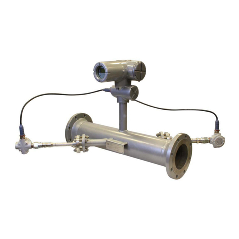
Fig. 1 Standard Insertion Flow Meter Fig. 2 Flanged Flow Meter
(Pipe size DN100-DN500) (Pipe size DN10-DN80)
Fig. 3 Hot-tapped Insertion Flow Meter
(Pipe size DN100-DN4000. Special requirements please contact us)
The insertion sensor of compact insertion flow meter should be inserted to axis of pipe, and the length of
the insertion sensor is decided by pipe size, please confirm the pipe size when ordering. If the insertion
sensor can’t be inserted to axis of pipe, the manufacturer will provide a calibration factor to achieve an
accurate measurement.

- 8 -
3.3.2 Dimensions
Dimensions of standard insertion sensor Dimensions of hot-tapped insertion sensor
The dimensions of flanged sensor
PN1.6Mpa Plane and surface plate flat welding steel pipe flanges (Unit: mm)
Nominal
Diameter
Flange
Outer
diameter
Center
Hole
Screw
Hole
Screw
Thread
Sealing Face
Flange
Thickness
Pipeline
Length
DN
D
k
n×L
d
f
C
L
15
95
65
4×14
M12
46
2
14
280
20
105
75
4×14
M12
56
2
16
280
25
115
85
4×14
M12
65
2
16
280
32
140
100
4×18
M16
76
2
18
350
40
150
110
4×18
M16
84
2
18
350
50
165
125
4×18
M16
99
2
20
350
65
185
145
4×18
M16
118
2
20
400
80
200
160
8×18
M16
132
2
20
400
100
220
180
8×18
M16
156
2
22
500

- 9 -
For DN15-DN80, the meter can be made with threading to connect.
The above table is used for rated pressure of 1.6MPa. If the rated pressure is more than 1.6MPa, please
contact us for special order.
4. Wiring
4.1 Preparation of wiring
You should read and connection method of supporting the use of thermal mass flowmeter
or other unit instrument system and requires careful - before connection;
The external cable recommended two core shielded cable and cable connection and
good sealing;
The explosion-proof products should be selected in accordance with the relevant
standard of BenAn instrument cable and make sure that the cable parameters meet the
explosion-proof instrument system requirements;
Working voltage range of DC18~30V. When the voltage is higher than DC30V, the
instrument will be damaged, and measures should be taken to prevent the supply voltage
from above 30V;
To the 24V DC power supply thermal mass flowmeter shall meet the requirements of
IEC-1010-1 or equivalent standard SELV safety extra low voltage;
Before the connection with the voltmeter to measure the power supply voltage, the
voltage is DC24V;

- 10 -
4.2 Terminal description
Terminal diagram
Mark
Description
L
AC85V~AC220V L
N
AC85V~AC220V N
24V
24V Power supply positive pole
0V
24V Power supply 0V
P+
Pulse output positive pole
P-
Pulse output negative pole
I+
Current output positive pole
I-
Current output negative pole
485+/A
RS485 communication interface A
485-/B
RS485 communication interface B
ALARM1
Alarm output 1
ALARM2
Alarm output 2
Sensor terminal
PT20/PT300 is
Default combination ,
Other optional sensors
PT20/PT200、PT20/PT1000、
RS232 interface, baud rate is 9600.
Function1 the same with S485 interface
Function2 is used to upgrade the instrument program
Upgrade button, press the button, the RS232 interface for
function two, at this time the instrument is not displayed in
the upgrade ready!
Under normal circumstances, no need to press the button.

- 11 -
4.3 Terminal connection
Pulse output wiring
Analog output wiring

- 12 -
5. technical parameters
Power Supply
Supply Voltage
24VDC/1.5A
Allow residual ripple:0~100Hz,
Upp= 30Mv,Uss<10mV
Maximum noise:500Hz~10KHz ,Ueff = 2.0Mv
or 85~265V AC
Operating current
<650mA
Output
Output current mode
4~20mA/ Fixed current output
RS485 interface
Baud rate:1200/2400/4800/9600/19200
Data:8
Check:None/Odd/Even
Stop:1
RS232 interface
Baud rate:9600 ,Data:8,Check:None ,
Stop:1
Communication protocol
MODBUS RTU

- 13 -
6.Install
A stable flow field is the premise of the accurate measurement of the thermal instrument. Therfore,
please note following points when installing the instrument.
6.1 Installation direction
●Horizontal installation
The process pressure must not exceed 2MPa when installing
●Vertical installation
The process pressure must not exceed 2MPa when installing
6.2 Pipe requirements
If the Interference sources (i.e. bends, reduce, valves, T tubes, ect.) exist on the instrument intake
pipe, measures must be taken to minimize their impacts on measurement performance
The following diagrams describe the recommended minimum straightway lengths of some types of
pipe.
The straightway length should be as long as possible while the room is sufficient. Without the
consideration of other factors, the recommended minimum straightway lengths are:
front straightway length: 20×DN
rare straightway length: 5×DN
The recommended straightway lengths are minimum, increased straightway lengths improve the
instrument performance.
If multiple Interference sources exist in front of instrument, the recommended straightway lengths
are absolute.

- 14 -
The contorl valves are recommended to be place at rare of instrument.
For the light gases, such as helium and hydrogen, front straightway lengths should be doubled.
a = front straightway length b = rare straightway lengths
Control valves and shut-off valves should be palced at rare of instrument.

- 15 -
6.3 Installation Steps
The base of thermal flowmeter
The base of Hot-tapped insertion type The base of standard insertion type
No welding in explosive environment
Carry out the welding operation in accordance with the requirements of special environment.
When installing, place the base on the top of pipe, and make the through-hole of base be perpendicular
to axis of pipe. The good welding location of base and welding process is as below.
Good welding location of base
The installation of standard insertion type
Identify an appropriate location for the flow meter.
Confirm the inner diameter and wall thickness of pipe
Place the other part of meter into ball valve, and calculate the insertion depth according to the inner
diameter and wall thickness of pipe. This step doesn’t need to screw the nut by hand.
Turn the connecting rod of sensor to make the mark direction of sensor as the same flow direction.
According the calculated data on site, ensure the insertion depth by corresponding calibration on
the connecting rod, and then screw the nut tightly.
If the meter is horizontal installation, the display of the meter can be installed in the direction of 90°,
Before Welding, the base should be
processed as the same as the
circular arc of pipe to ensure sealing

- 16 -
180°or 270°to meet various requirements.
The installation of hot-tapped insertion type
Before installation, please conform the connection type and install fittings.
Before installation, the site must be shut down, and strictly follow the rules of factory.
Identify an appropriate location for the flow meter.
According to length requirement of meter, cut the pipe, and install the flanges and bolts on the pipe.
Ensure the mark direction of meter is as the same flow direction, the display is perpendicular to
horizontal plane, the axis of pipeline is paralleled to horizontal plane, the error can’t be more than
±2.5, and then fix the meter by bolts.

- 17 -
7.Operating the instrument
7.1 Keyboard and display
Display
Keyboard
Cancel/Exit Key
Shift Key
Modify/Page Key
Confirm/Enter Key

- 18 -
7.2 Menu Instruction
7.2.1 Display sreens
Switch between 6 display screens by pressing (the page down key). Pressing Entrer key can enter
currently displaied menu. Back to flow dispaly screen from non flow display screens by pressing Cancel
key
Display the instant flow rate and
the unit of instant flow rate.
Cumulative flow and the unit of
Cumulative flow
The cumulative flow has 10
digits dsiplay, if the cumulative
flow is greater than 9999999, a
carry is generated and indicated
by
Display the instant flow
velocity, the unit is fixed as m/s.
0 and 3.1 indicate the range of
velocity while this range is varied
with the setting instrument
measuring range. The velocity
of medium is displayed
dynamically.
Present value of output
current. The bar at bottom
indicates the percentage of
output current in its range.
The indicators of upper and
lower alarm states. The ralies
are nomally on without alarm.
Historical data, the last data for
the current time point of the data,
the data interval can be set.
Didplay of all information.

- 19 -
7.2.2 Menu selecting and password entering
Press Modify/Page Key to select the menu.
Menu Selecting
SET: Setting of basic parameters
CLR: Setting the integer and decimal of cumulative flow
ImA: Setting the current parameters
ALM: Setting the alarm parameters
COM: settings of RS485 communication
CAL: Calibrate instrument
ADJ: Correction flow value
SYS: Setting the system parameters
QHD: Query history data
CHK: Instrument self-test
SAV: Save and restore paramters
SET: Setting of basic parameters , enter:1000
CLR: Setting the integer and decimal of cumulative flow ,
enter:1000
ImA: Setting the current parameters, enter:1000
ALM: Setting the alarm parameters, enter:1000
COM: settings of RS485 communication , enter:1000
CAL: Calibrate instrument, enter:0603
ADJ: Correction flow value, enter:1000
SYS: Setting the system parameters, enter:1000
QHD: Query history data, None password required
CHK: Instrument self-test, None password required
SAV: Save and restore paramters, None password required

- 20 -
Press Shift Key to select the menu item.
To set the basic parameters, move the black background cursor to "SETTINGS" item, press Enter key
and the password entering screen appears. Press Enter Key once more, to switch to password entering
model (prompted by blinkong cursor). Enter the password and press Enter key again. Once the password
is correct, the basic parameter setting screen appears or an "Error" message is given if the password is
incorrect.
Table of contents

