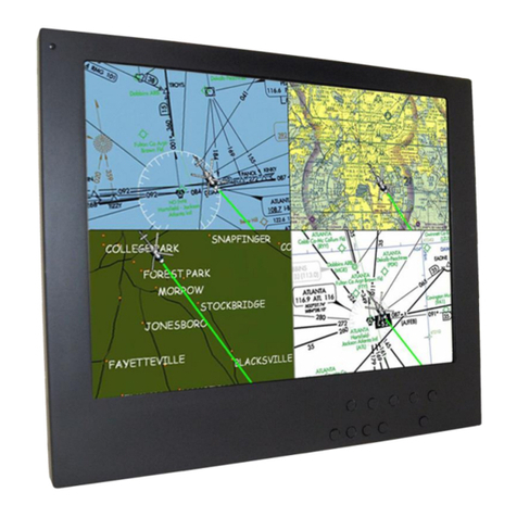
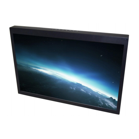
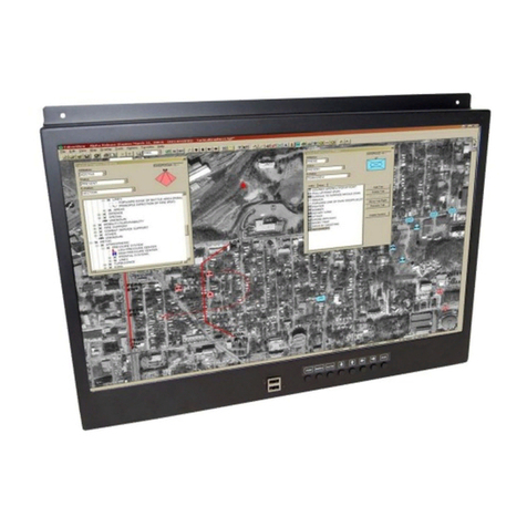
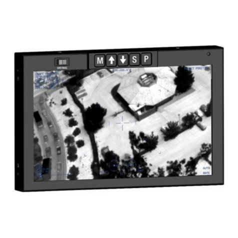
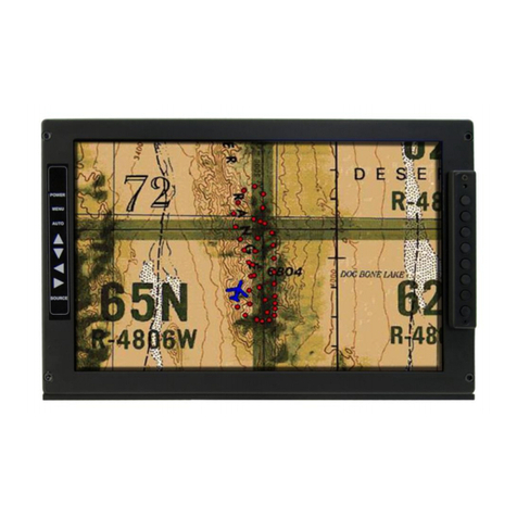
FDS FD215CV-C-7 User manual

Document Number:
MAN –FD215CV-C-7
Rev:
B
Revision Date:
01/10/2017
Page 1 of 25
©2017 FDS Avionics Corp.
All Rights Reserved.
TECHNICAL SUPPORT
470-239-7421 or FDSAvionics.com
Installation and Operation Manual
FD215CV-C-7
21.5” Widescreen HD Display

Document Number:
MAN –FD215CV-C-7
Rev:
B
Revision Date:
01/10/2017
Page 2 of 25
©2017 FDS Avionics Corp.
All Rights Reserved.
TECHNICAL SUPPORT
470-239-7421 or FDSAvionics.com
Table of Contents
General Information......................................................................................................................3
1. Front View..........................................................................................................................3
2. Additional Information....................................................................................................3
Specifications.............................................................................................................................4
Installation Instructions ..........................................................................................................4
Power ...........................................................................................................................................4
Wiring Suggestions ..................................................................................................................5
Power and Ground Wiring.......................................................................................................6
Rear View with Connectors ....................................................................................................7
Power/Video...............................................................................................................................8
VGA Video Pin out ...................................................................................................................9
DB-9 Pin out........................................................................................................................ 10-11
How to Change from VGA (Analog) to DVI (Digital) Inputs ..................................... 12-13
Operation Instructions...........................................................................................................14
Button Control..........................................................................................................................15
Quad Screen or Full Screen............................................................................................... 16-21
Technical Drawing..................................................................................................................22
Technical Support...................................................................................................................23
Instructions for Continued Airworthiness ........................................................................23
Warranty ...................................................................................................................................24
Log of Revisions......................................................................................................................25

Document Number:
MAN –FD215CV-C-7
Rev:
B
Revision Date:
01/10/2017
Page 3 of 25
©2017 FDS Avionics Corp.
All Rights Reserved.
TECHNICAL SUPPORT
470-239-7421 or FDSAvionics.com
General Information
The FD215CV-C-7 is a special mission HD monitor which is designed to be mounted in a
standard 19-inch rack. This display includes quad screen vide with picture in picture (PIP)
Capability.
Front View
Additional Information
The FD215CV-C-7 utilizes a state of the art digital video decoding chipset for all video inputs.
Three video sources are activated: HD-SDI, with input from an internal quad board for viewing
up to 4 HD Video inputs, DVI, and VGA (for computer graphics i.e. moving maps).
The LCD is protected with a .060” non-glare Lexan lens to prevent scratching of the LCD, and
to meet stringent FAA abrasive load criteria.

Document Number:
MAN –FD215CV-C-7
Rev:
B
Revision Date:
01/10/2017
Page 4 of 25
©2017 FDS Avionics Corp.
All Rights Reserved.
TECHNICAL SUPPORT
470-239-7421 or FDSAvionics.com
Specifications
Display Type
21.5” TFT Color LCD
Display Color
16.7 Million Colors
Screen Resolution
1920 X 1080
Screen Control
On Screen Display Menu
Brightness
300 cd/m2
Dimensions
20.0”(W) x 14.52”(H) x 2.78”(D)
Display Size
18.82”(W) x 10.61”(H)
Weight
10 lbs 13 oz
Operating Temperatures
0-50º C (32-122 F)
Power
28V DC @ 3 Amps
PC & Video Input
Analog RGB/VGA, HD-SDI, Digital (DVI-D)
Video Type
NTSC/PAL
Viewing Angle
170° Horizontally
160° Vertically
Materials
Aluminum
Installation Instructions
All cabin equipment, such as the FD215CV-C-7, should be installed on a non-essential bus and
have a dedicated circuit breaker.
The FD215CV-C-7 is designed to mount into a standard electronics rack using (4) 10-32 Machine
screws. See installation drawing on page 16 for measurement details.
Power
This is a 28VDC monitor that requires 3.0 Amps of power to operate. The unit turns on
automatically upon power application.

Document Number:
MAN –FD215CV-C-7
Rev:
B
Revision Date:
01/10/2017
Page 5 of 25
©2017 FDS Avionics Corp.
All Rights Reserved.
TECHNICAL SUPPORT
470-239-7421 or FDSAvionics.com
Wiring Suggestions
Shields used on wire bundles and power should be grounded to the connector at the source and
left floating at the display. Shields for USB, SDI data, and video should be connected at both
ends.
Avoid routing video wiring parallel to:
AC wiring
Strobe wiring
DC motor supply cables
Inverter cabling
Or any other potential noise source.
We recommend coax cables be terminated using solder sleeve coaxial cable
terminators such as Raychem Part Number CWT-4174-W122-5/9.

Document Number:
MAN –FD215CV-C-7
Rev:
B
Revision Date:
01/10/2017
Page 6 of 25
©2017 FDS Avionics Corp.
All Rights Reserved.
TECHNICAL SUPPORT
470-239-7421 or FDSAvionics.com
Power and Ground Wiring
This is a 28VDC monitor that requires 3 amps of power to operate. To operate properly this
monitor requires an input voltage of 24-29VDC.
The rated current of the equipment and associated voltage drop should be taken into
consideration when selecting wire gauge. The following example is based on an install with a
28VDC power system and a total of 50 feet of wire between the circuit breaker, monitor and
ground.
Example: 22awg wire has 16.2 Ohms per 1000 feet, this equates to .81 Ohms for 50 feet. 3 Amps
of current on .81 Ohms will drop 2.43 Volts.
Resistance of Wire Type M22759/16-**
(** = Gauge)
Gauge (AWG)
OHMS/1000’
24
26.20
22
16.20
20
9.88
16
4.81
12
2.02
10
1.26
8
.70
Also, use short heavy gauge wire and a clean tight connection for ground.
It is the installer's responsibility to understand the product's requirements to install the product
in compliance with industry standards and safety.

Document Number:
MAN –FD215CV-C-7
Rev:
B
Revision Date:
01/10/2017
Page 7 of 25
©2017 FDS Avionics Corp.
All Rights Reserved.
TECHNICAL SUPPORT
470-239-7421 or FDSAvionics.com
Rear View with Connectors
CONTROL
PORT
VGA INPUT
DVI-D INPUT
HDDSI OUT
SDI OUTPUT
(FROM QUAD)
BOARD)
SDI INPUTS (4)
28 VDC INPUT

Document Number:
MAN –FD215CV-C-7
Rev:
B
Revision Date:
01/10/2017
Page 8 of 25
©2017 FDS Avionics Corp.
All Rights Reserved.
TECHNICAL SUPPORT
470-239-7421 or FDSAvionics.com
Power/Video
Pin out for 28V PWR –D38999 connector (supplied)
Connector P/N: D38999/26FB5SA or Equivalent
Crimp Contacts P/N: M39029/56-351 or Equivalent
MATING FACE
Pin
Number
Description
A
28VDC Power
B
28VDC Power
C
28VDC Ground
D
28VDC Ground
E
N/C

Document Number:
MAN –FD215CV-C-7
Rev:
B
Revision Date:
01/10/2017
Page 9 of 25
©2017 FDS Avionics Corp.
All Rights Reserved.
TECHNICAL SUPPORT
470-239-7421 or FDSAvionics.com
VGA Video
Accepts Industry Standard VGA connection
Pin
Number
Description
1
Red Video
2
Green Video
3
Blue Video
4
Reserved
5
H-Sync Ground
6
Red Return
7
Green Return
8
Blue Return
9
+5V DC
10
V-Sync Ground
11
Reserved
12
Reserved
13
Horizontal Sync
14
Vertical Sync
15
Reserved

Document Number:
MAN –FD215CV-C-7
Rev:
B
Revision Date:
01/10/2017
Page 10 of 25
©2017 FDS Avionics Corp.
All Rights Reserved.
TECHNICAL SUPPORT
470-239-7421 or FDSAvionics.com
Pinout for DB-9
Part Numbers for DB-9 connectors, manufactured by Tyco or Amp.
D-sub, 9 contact receptacle (female) P/N 205203-1
DB9F pins P/N M39029/63-368
Wiring Diagram
Pin
Number
Description
1
+5V USB POWER (RED)
2
DATA + (GREEN)
3
DATA - (WHITE)
4
POWER RETURN (BLACK)
5
CHASSIS GROUND (SHIELD)
6
VGA/DVI JUMPER*
7
VGA/DVI JUMPER*
8
N/C
9
N/C
*Add jumper wires for DVI video selection. Remove jumper wires for VGA video selection.
Maximum jumper wire length is 2”.
Pin out for HD-SDI Inputs
(Standard BNC –75 OHM) –31-242
Pin
Description
Center
Video Signal
Shell
Video Return

Document Number:
MAN –FD215CV-C-7
Rev:
B
Revision Date:
01/10/2017
Page 11 of 25
©2017 FDS Avionics Corp.
All Rights Reserved.
TECHNICAL SUPPORT
470-239-7421 or FDSAvionics.com
Pin out for DVI-D
Accepts a standard DVI-D (Single Link) male connector (supplied)
View into mounted receptacle
Pin
Number
Description
1
TMDS data 2-
2
TMDS data 2+
3
TMDS data 2 shield
4
N/C
5
N/C
6
DDC clock
7
DDC data
8
N/C
9
TMDS data 1-
10
TMDS data 1+
11
TMDS data 1 shield
12
N/C
13
N/C
14
+5 V
15
Ground
16
Hot plug detect
17
TMDS data 0-
18
TMDS data 0+
19
TMDS data 0 shield
20
N/C
21
N/C
22
TMDS clock shield
23
TMDS clock+
24
TMDS clock-
C1
N/C
C2
N/C
C3
N/C
C4
N/C
C5
N/C

Document Number:
MAN –FD215CV-C-7
Rev:
B
Revision Date:
01/10/2017
Page 12 of 25
©2017 FDS Avionics Corp.
All Rights Reserved.
TECHNICAL SUPPORT
470-239-7421 or FDSAvionics.com
How to Change from VGA (analog) to DVI (digital) inputs:
This unit is capable of swapping between the 2 inputs (either VGA and SDI) or (DVI and SDI).
The factory menu selections to change from VGA to DVI or vice versa are as follows:
Press and hold down the DOWN ARROW button (after several seconds, this menu will open
on the monitor display)
Press the down arrow button 3 times until the following screen is displayed:

Document Number:
MAN –FD215CV-C-7
Rev:
B
Revision Date:
01/10/2017
Page 13 of 25
©2017 FDS Avionics Corp.
All Rights Reserved.
TECHNICAL SUPPORT
470-239-7421 or FDSAvionics.com
Using the up/down and right/left arrow buttons to select or deselect DIGITAL or ANALOG
selections. Note: ANALOG or DIGITAL should be selected, not both.
If VGA is chosen the screen will look like this:
To switch over to Digital just disable the Analog and Enable the Digital. The screen will
look like this:

Document Number:
MAN –FD215CV-C-7
Rev:
B
Revision Date:
01/10/2017
Page 14 of 25
©2017 FDS Avionics Corp.
All Rights Reserved.
TECHNICAL SUPPORT
470-239-7421 or FDSAvionics.com
Operation Instructions
The FD215CV-C-7 is continuously on but can be de-energized by removing power from the
video system. No pilot or aircrew action is necessary during flight or ground operation.
The operator will be able to change the video display on the FD215CV-C-7 by pressing the
computer button to select the VGA or DVI input as programmed. HD-SDI inputs can be
selected by pressing buttons 1 through 4. When the Quad button is pushed all 4 HD-SDI inputs
will be displayed. The picture in picture button will toggle between the selected camera view and
the computer input (VGA or DVI). When the operator presses the PIP button (picture in
picture) the elected camera input will be overlayed on top of the map image. When the PIP is
pressed again the primary view will switch between the computer input and the selected camera
input. When the PIP button is pressed and held the display will switch between the computer
input and the HD-SDI input in full screen view.
When applying 28VDC power, the display will turn on and look for a valid input on the last
known source. If no input is found, the display will go to standby mode. Pressing the Select
button will select new video input.

Document Number:
MAN –FD215CV-C-7
Rev:
B
Revision Date:
01/10/2017
Page 15 of 25
©2017 FDS Avionics Corp.
All Rights Reserved.
TECHNICAL SUPPORT
470-239-7421 or FDSAvionics.com
Button Controls
Located on the front right of the FD215CV-C-7 are two sets of 4 buttons. These buttons are
used to power up the unit and navigate through the different menus. The menu button is used
as a toggle, push to view the menu screens, push again to exit.
BUTTON
DESCRIPTION
BUTTON
DESCRIPTION
Moves the highlight icon up to
the function that user wants.
MENU
Activates the OSD
menu or goes to
previous menu.
Decreases the adjustment of
the selected function.
SCE
Selects the Input
Signal among HD-SDI,
DVI, and VGA.
Increases the adjustment of
the selected function.
AUTO
Auto-adjustment in
RGB.
Moves the highlight icon
down to the function that user
wants.
PWR
Turns ON/OFF the
system.
MENU
SCE
AUTO
PWR

Document Number:
MAN –FD215CV-C-7
Rev:
B
Revision Date:
01/10/2017
Page 16 of 25
©2017 FDS Avionics Corp.
All Rights Reserved.
TECHNICAL SUPPORT
470-239-7421 or FDSAvionics.com
Quad Screen or Full Screen
This display has the capability to display a quad screen or full screen from any of the four HDSDI
inputs. The image seen here is the bottom view of the FD215CV-C-7 LCD. Connecting the SDI
input to the output of the attached quad box on the unit will enable the operator to view any image
from any of the connected screens on board the aircraft. Simply connect the other units to the
inputs labelled 1 through 4 on the quad box to initiate the connection.
The button display below is centrally located on the bottom of the bezel display of the unit. The
number keys will allow you to look at that connection display or the user can use PIP (Picture in
Picture) to set their own preference. The QUAD button will display all connected HDSDI inputs at
once. The SWAP Button will enable the user to move around through the multiple HDSDI
connections.
4 3 2 1
1 2 3 4
Q
U
A
D
S
W
A
P
C
O
M
P
PIP

Document Number:
MAN –FD215CV-C-7
Rev:
B
Revision Date:
01/10/2017
Page 17 of 25
©2017 FDS Avionics Corp.
All Rights Reserved.
TECHNICAL SUPPORT
470-239-7421 or FDSAvionics.com
Operation of the Video selection Switch group:
The slide-out monitor has two window fields: Main and Picture-in-Picture (PIP).
Power-on Default: Computer is displayed in the Main window and quad video is
displayed in the PIP window (non-volatile memory).
Picture-in-Picture (PIP) default size and location = Medium and Top Right (Non-volatile
memory) Opacity of the PIP image is set to 80%.
Mutually exclusive video modes:
With PIP active, the Main and PIP windows display opposing video (1, 2, 3, 4, or
QUAD) and computer (COMP) inputs.
or
Cannot have the computer source displayed within both the Main and the PIP windows at same
time.
Cannot have a video source (1, 2, 3, 4 or QUAD) displayed within both the Main and the PIP
windows at same time.

Document Number:
MAN –FD215CV-C-7
Rev:
B
Revision Date:
01/10/2017
Page 18 of 25
©2017 FDS Avionics Corp.
All Rights Reserved.
TECHNICAL SUPPORT
470-239-7421 or FDSAvionics.com
Overall Button Operation:
Video Select buttons accept Long press and Short press commands. Long Press (LP) button
function: press and hold for > ¾ second. Activation is at time-out (release not required).
COMP Button:
COMP (Computer): Short press –changes the Main display to the computer input; either the
VGA or DVI input full screen.
PIP Off: displays computer in the Main
PIP On:
oIf the computer input is in the Main window: no change. Video PIP remains.
oIf the computer input is in the PIP window: functions like a LP PIP, moving the computer
display to the Main window and the video display to the PIP window
Long Press (LP) of COMP moves that computer input to Main and turns PIP Off
oReturning to PIP with COMP in the Main window, displays the last used video input in
the PIP window

Document Number:
MAN –FD215CV-C-7
Rev:
B
Revision Date:
01/10/2017
Page 19 of 25
©2017 FDS Avionics Corp.
All Rights Reserved.
TECHNICAL SUPPORT
470-239-7421 or FDSAvionics.com
PIP Button:
Short press of PIP enables and disables the PIP display. If PIP is disabled, then a short press
enables it. If it is enabled, then a short press disables it.
When enabling PIP, if the computer is displayed in the main screen area, then the PIP area
contains the last requested Quad, 1, 2, 3, or 4 video source.
If any video source is displayed in the main screen area, then the PIP area contains the
computer source.
Long press of PIP:
If PIP mode is enabled then a long press of the PIP button swaps the PIP and Main images.
If PIP mode is not enabled, then a long press of the PIP button will swap the last requested
computer source and the last requested video source. If computer is currently displayed, then
a long press of the PIP button will put the last requested video channel (SDI 1, SDI2, SDI3,
SDI4, or Quad view of all four SDI sources) into the full screen view on the monitor. If any of
the video modes are currently displayed, then a long press of the PIP button will put the last
requested computer channel into the full screen view on the monitor.
oWith PIP On: Swaps sources between Main window and PIP window
oWith PIP Off: Swaps sources (computer or video) on the Main window

Document Number:
MAN –FD215CV-C-7
Rev:
B
Revision Date:
01/10/2017
Page 20 of 25
©2017 FDS Avionics Corp.
All Rights Reserved.
TECHNICAL SUPPORT
470-239-7421 or FDSAvionics.com
Buttons: 1, 2, 3, 4:
Short press - Changes the display to the selected Video source as follows:
oWith PIP Off: switches the Main window to the selected video source (1, 2, 3, or 4)
oWith PIP On and video in the Main window: switches the Main window to the selected video
source (1, 2, 3, or 4)
oWith PIP On and video in the PIP window: switches the PIP window to the selected video source
(1, 2, 3, or 4)
Long Press (LP) moves that video source to the Main window and turns PIP Off
oReturning to PIP with the selected video source (1, 2, 3, or 4) in the Main window, displays
COMP in the PIP window
Table of contents
Other FDS Monitor manuals
FDS
FDS FD141CV-C-3 User manual

FDS
FDS FD101DD-BH User manual
FDS
FDS FD171CV VER HDSDI User manual
FDS
FDS FDPMAID Series User manual
FDS
FDS FD220CV-C-1 User manual
FDS
FDS FD171CV-C-4 User manual
FDS
FDS FD090CV User manual
FDS
FDS FD141CV-C-1 User manual
FDS
FDS FD201CV-C-1 User manual

FDS
FDS FD215CV-C-6 User manual
