FDS FD102CV-LP-S User manual

Document Number:
MAN –FD102CV-LP-S
Rev:
B
Revision Date:
06/02/2017
Page 1 of 22
©2017 FDS Avionics Corp.
All Rights Reserved.
TECHNICAL SUPPORT
470-239-7421 or FDSAvionics.com
Installation and Operation
Manual
FD102CV-LP-S
Low Profile 10.1” Widescreen LCD

Document Number:
MAN –FD102CV-LP-S
Rev:
B
Revision Date:
06/02/2017
Page 2 of 22
©2017 FDS Avionics Corp.
All Rights Reserved.
TECHNICAL SUPPORT
470-239-7421 or FDSAvionics.com
Specifications
Display
FD102CV-LP-S
Panel Technology
TN, Normally White
Diagonal Screen Size
10.1” Widescreen TFT Color LCD
Native Resolution
1024x600
Pixel Pitch
.21525 mm x .21525 mm
Contrast Ratio
500:1
Viewing Angle (L, R, U, D)
70/70/50/60
Supported Resolution
Up to 1920 x 10810
Brightness
250cd/ m²
Power
Power
28 V DC input @ .3 Amps
Inrush Current
12.4 Amps Peak
1.92 Amps @ 500 µS
0.30 Amps steady state @ 1mS
Environmental
Conditions
Operating Temperatures
0ºC/ 50ºC
Storage Temperature
-20ºC/ 60ºC
Dimensions
Display Size
8.66” (W) x 5.07” (H)
Display Dimensions
9.55”(W) x 7.30”(H) x 0.80”(D)
LCD Weight
3 lbs. 15 oz.
Materials
Aluminum
Features
PC & Video Input
VGA, 2 Composite Video
Video type Supported
NTSC, PAL
Screen Control
On Screen Display Menu
Remote control
IR, included

Document Number:
MAN –FD102CV-LP-S
Rev:
B
Revision Date:
06/02/2017
Page 3 of 22
©2017 FDS Avionics Corp.
All Rights Reserved.
TECHNICAL SUPPORT
470-239-7421 or FDSAvionics.com
Connectivity
Product
CERTIFICATIONS
INPUTS
OUTPUTS
COMMUNICATION
PMA
VGA
Infrared Port
COMP
AUDIO
SD CARD
USB PORT
SDI
VGA
AUDIO
COMPOSITE
HDMI
DVI-D
SD-SDI
HD-SDI
3G-SDI
RS232
RS485
CONTROL
CAN
IR REMOTE
FD102CV-LP-S
1
2
1

Document Number:
MAN –FD102CV-LP-S
Rev:
B
Revision Date:
06/02/2017
Page 4 of 22
©2017 FDS Avionics Corp.
All Rights Reserved.
TECHNICAL SUPPORT
470-239-7421 or FDSAvionics.com
Table of Contents
General Information/ Front View/ Additional Information................................5
Installation Instructions......................................................................................6
Power ...................................................................................................................6
Wiring Suggestions.............................................................................................6
Composite and Audio Wiring.............................................................................7
VGA Wiring ..........................................................................................................7
Power Ground Wiring .........................................................................................8
Operation Instructions/Button Control..............................................................9
Remote Control Buttons...................................................................................10
Accessing the OSD Menu/ OSD Menu.............................................................11
Image Setting.....................................................................................................12
Display Setting ..................................................................................................13
Color Temp........................................................................................................14
User....................................................................................................................15
Windows ............................................................................................................16
OSD ....................................................................................................................17
Setup..................................................................................................................18
Technical Drawing.............................................................................................19
Technical Support.............................................................................................20
Instructions for Continued Airworthiness ......................................................20
Warranty.............................................................................................................21
Log of Revisions ...............................................................................................22

Document Number:
MAN –FD102CV-LP-S
Rev:
B
Revision Date:
06/02/2017
Page 5 of 22
©2017 FDS Avionics Corp.
All Rights Reserved.
TECHNICAL SUPPORT
470-239-7421 or FDSAvionics.com
General Information
This high resolution Low Profile 10.1”Widescreen LCD is built with retrofit aircraft
integration in mind, this display can switch between three video input sources using an
infrared remote or the control buttons on the bottom face of the unit. It is perfect for cabin
video and graphical entertainment. The FD102CV-LP-S has features that allow installation
in the smallest of mounting areas with the minimum of interface equipment.
Front View
Additional Information
The 10.1” Widescreen LCD utilizes a state of the art digital video decoding chipset for the
analog video input. The three video sources in order of picture quality are VGA (computer
graphics, like Moving Maps), and two (2x) Composite Video (DVD, Camera or VCR). Both
NTSC and PAL formats are auto-detected.
The FD102CV-LP-S can also be connected to existing video switchers and can take a
composite video input from a selector interface box. In this case, multiple input sources
can be selected and displayed on the monitor.

Document Number:
MAN –FD102CV-LP-S
Rev:
B
Revision Date:
06/02/2017
Page 6 of 22
©2017 FDS Avionics Corp.
All Rights Reserved.
TECHNICAL SUPPORT
470-239-7421 or FDSAvionics.com
Installation Instructions
All cabin entertainment equipment, such as the FD102CV-LP-S, should be installed on a
non-essential bus and have a dedicated circuit breaker. It is a requirement that a switch be
installed in the cockpit so that the pilot can de-energize the entertainment system should it
become necessary. See mounting specification drawing ICD-129 at end of this manual.
Power
This is a 28VDC monitor that requires .3 Amps of power to operate. The unit turns on
automatically upon power application.
Wiring Suggestions
All shields should be grounded to the connector at the source, and floating at the display.
Avoid routing video wiring parallel to:
•AC wiring
•Strobe wiring
•DC motor supply cables
•Inverter cabling
•Or any other potential noise source

Document Number:
MAN –FD102CV-LP-S
Rev:
B
Revision Date:
06/02/2017
Page 7 of 22
©2017 FDS Avionics Corp.
All Rights Reserved.
TECHNICAL SUPPORT
470-239-7421 or FDSAvionics.com
Composite and Audio Wiring
Recommended cable for s-video/composite and audio purposes is PIC 75 Ohm Coax, P/N
V76261. This is a lightweight, flexible, and low signal loss cable which meets FAA
flammability requirements of FAR 23.1359(d), FAR 25.853(a) and FAR 25.869(a)(4).
Similar aviation coaxial cable can be used from other vendors, as well.
Some aircraft are prone to AC noise –we recommend adding to the composite source a
75Ohm video isolation transformer such as Deerfield Laboratory, Inc. Part No. 162-1
(www.deerfieldlab.com, (650) 632-4090). In most cases this should be added to the video
output of the source.
VGA Wiring
Recommended cable for VGA purpose is Carlisle (formally known as ECS) P/N 453005. This
is a single shielded cable containing 5 separate coaxial cables, color-coded to match the
functions of the wires.
Document Number:
MAN –FD102CV-LP-S
Rev:
B
Revision Date:
06/02/2017
Page 8 of 22
©2017 FDS Avionics Corp.
All Rights Reserved.
TECHNICAL SUPPORT
470-239-7421 or FDSAvionics.com
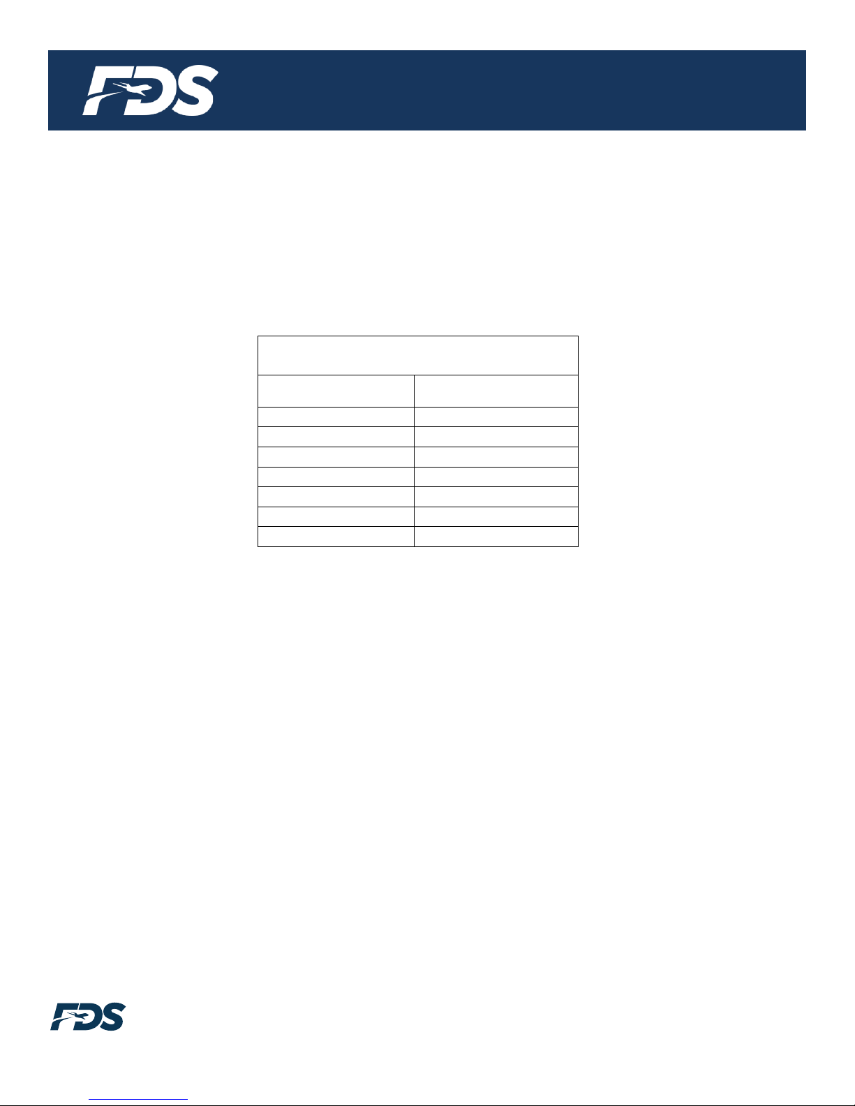
Power and Ground Wiring
The rated current of the equipment and associated voltage drop should be taken into
consideration when selecting wire gauge. The following example is based on an install
with a 28VDC power system, 1.5-amp equipment load and a total of 50 feet of wire
between the circuit breaker, monitor and ground.
Example: 22awg wire has 16.2 Ohms per 1000 feet, this equates to .81 Ohms for 50 feet.
1.5 Amp of current on .81 Ohms will drop 1.22 Volts.
Resistance of Wire Type M22759/16-**
(** = Gauge)
Gauge (AWG)
OHMS/1000’
24
26.20
22
16.20
20
9.88
16
4.81
12
2.02
10
1.26
8
.701
Also, use short heavy gauge wire and a clean tight connection for ground.
It is the installer's responsibility to understand the product's requirements to install the
product in compliance with industry standards and safety.
Operation Instructions
The FD102CV-LP-S is continuously on but can be de-energized by removing power from
the entertainment system. No pilot or aircrew action is necessary during flight or ground
operation.
Passengers can change the video output from the FD102CV-LP-S using the video source
select switch on the included IR remote.
The IR LED, located on the top of the monitor, must be visible to the remote for wireless
operation.

Document Number:
MAN –FD102CV-LP-S
Rev:
B
Revision Date:
06/02/2017
Page 9 of 22
©2017 FDS Avionics Corp.
All Rights Reserved.
TECHNICAL SUPPORT
470-239-7421 or FDSAvionics.com
Button Controls
The button controls are located on the bottom of the monitor on the right side.
Button functions are described in the table below.
BUTTON
DESCRIPTION
1
POWER
Toggles the power ON or OFF. Also, wakes the display up from SLEEP
mode.
2
MENU
Opens the OSD MENU.
3
SOURCE
Switches between sources coming into the display.
4
DOWN
Moves to the next selection in the OSD menu.
5
UP
Moves to the previous selection in the OSD menu.

Document Number:
MAN –FD102CV-LP-S
Rev:
B
Revision Date:
06/02/2017
Page 10 of 22
©2017 FDS Avionics Corp.
All Rights Reserved.
TECHNICAL SUPPORT
470-239-7421 or FDSAvionics.com
Remote Control Buttons
The IR LED, located on the front of the monitor, must be visible to the remote for wireless
operation. Refer to button controls on previous page for remote control button functions.
POWER - System On/off
SOURCE - Change functions
MENU - Menu On/Off
UP/DOWN –Menu Move
LEFT/RIGHT –Menu Move &Brightness
control
* Below keys used for special function.
* Before using the Remote control for the
first time, ensure two AAA batteries are
installed.

Document Number:
MAN –FD102CV-LP-S
Rev:
B
Revision Date:
06/02/2017
Page 11 of 22
©2017 FDS Avionics Corp.
All Rights Reserved.
TECHNICAL SUPPORT
470-239-7421 or FDSAvionics.com
Accessing the OSD Menu
1. With the OSD off, push the MENU button to activate the main OSD menu.
2. Use the SOURCE button to move from sub menu to another. To enter a submenu, use the
UP button. Use the SOURCE button to move down the available selections within a
submenu. Use the UP and DOWN key to change values once the desired value is
highlighted.
3. Press the MENU button once to escape sub menus. Continue pressing the MENU button to
escape the OSD menu all together.
OSD Menus:
1. IMAGE Settings: BRIGHTNESS/CONTRAST/SATURATION/HUE/SHARPNESS/GAMMA
2. DISPLAY: SCAN MODE/ASPECT RATIO/HV DELAY
3. COLOR TEMP: MONO/6500K/7500K/9300K/USER MENU/RED/GREEN/BLUE
4. WINDOWS: MAIN INPUT/OSD MENU
a. OSD MENU: LANGUAGE/FLIP/TIMEOUT/H POS/V POS/BLEND LEVEL
5. SETUP: MAX BL/MIN BL/BACKLIGHT LEVEL/VIDEO PROCESSING MENU/BAUD
RATE/SERIAL ID/FACTORY RESET
a. VIDEO PROCESSING MENU: MPEG NR/DYNAMIC CONTRAST/MADI/TNR/CCS
Document Number:
MAN –FD102CV-LP-S
Rev:
B
Revision Date:
06/02/2017
Page 12 of 22
©2017 FDS Avionics Corp.
All Rights Reserved.
TECHNICAL SUPPORT
470-239-7421 or FDSAvionics.com
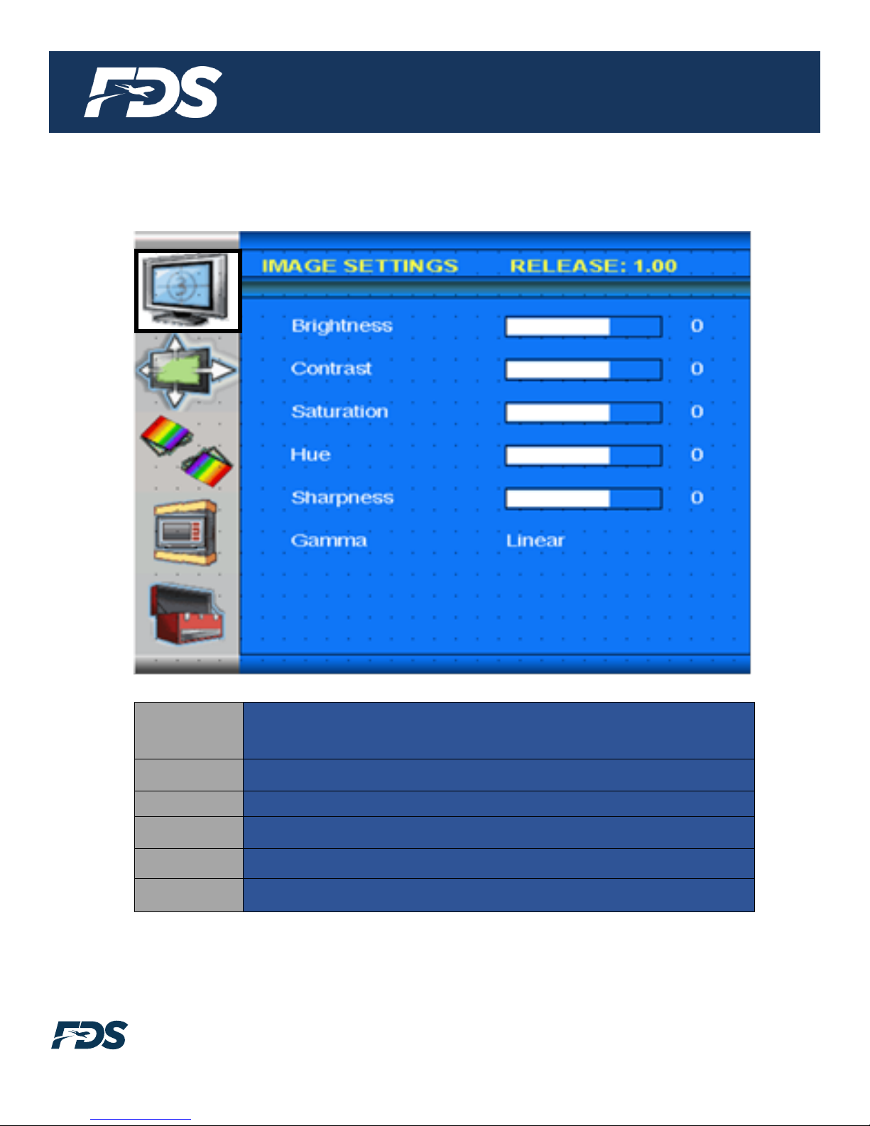
Image Settings
Brightness
Adjusts the brightness of the image. Note that this is not the same as
backlight intensity. Turning brightness up turns black pixels into light
grey pixels.
Contrast:
Adjusts the contrast of the image
Saturation:
Adjusts the saturation level of the image
Hue:
Adjusts the hue level of the image
Sharpness:
Adjusts the sharpness of the image
Gamma:
Compensates for non-linear response of an LCD panel

Document Number:
MAN –FD102CV-LP-S
Rev:
B
Revision Date:
06/02/2017
Page 13 of 22
©2017 FDS Avionics Corp.
All Rights Reserved.
TECHNICAL SUPPORT
470-239-7421 or FDSAvionics.com
Display Settings
Scan
Mode:
Adjusts the scan mode based on the desired selection: Zero Scan,
Over Scan, native scan, Under scan, Fit Width Scan. FDS Avionics
leaving this setting at Zero Scan.
Aspect
Ratio:
Adjusts the aspect ratio based on the desired selection: auto, full
screen, 16:9, 4:3, and native.
H/V Delay:
Delays horizontal and vertical sync. FDS Avionics recommends
leaving this setting off.

Document Number:
MAN –FD102CV-LP-S
Rev:
B
Revision Date:
06/02/2017
Page 14 of 22
©2017 FDS Avionics Corp.
All Rights Reserved.
TECHNICAL SUPPORT
470-239-7421 or FDSAvionics.com
Color Temp
COLOR
TEMP:
Adjusts the color temperature based on user selection. Options are
6500K, 7500K, 9300K, and User, Mono, Blue, Green

Document Number:
MAN –FD102CV-LP-S
Rev:
B
Revision Date:
06/02/2017
Page 15 of 22
©2017 FDS Avionics Corp.
All Rights Reserved.
TECHNICAL SUPPORT
470-239-7421 or FDSAvionics.com
User
User
The User defined color temperature submenu allows both the
changing of the Gain and Offsets of the Red, Green, and Blue
components.

Document Number:
MAN –FD102CV-LP-S
Rev:
B
Revision Date:
06/02/2017
Page 16 of 22
©2017 FDS Avionics Corp.
All Rights Reserved.
TECHNICAL SUPPORT
470-239-7421 or FDSAvionics.com
Windows
Main
Source
This allows changing the primary source of the display. This can
also be accomplished by using the select key or the IR remote.

Document Number:
MAN –FD102CV-LP-S
Rev:
B
Revision Date:
06/02/2017
Page 17 of 22
©2017 FDS Avionics Corp.
All Rights Reserved.
TECHNICAL SUPPORT
470-239-7421 or FDSAvionics.com
OSD
OSD
Allows the user to enter a submenu to adjust settings of the
OSD Menu
Language
Adjusts the OSD Language
FLIP
Adjusts the OSD mirroring: normal, H FLIP, V FLIP, HV FLIP
Timeout
Adjust the OSD timeout value.
H Pos
Adjust the OSD Horizontal position.
V Pos
Adjust the OSD Vertical position
Blend
Level
Adjusts the OSD transparency

Document Number:
MAN –FD102CV-LP-S
Rev:
B
Revision Date:
06/02/2017
Page 18 of 22
©2017 FDS Avionics Corp.
All Rights Reserved.
TECHNICAL SUPPORT
470-239-7421 or FDSAvionics.com
SETUP
Max
Backlight:
Limits the maximum level the backlight can be set to using the OSD
controls
Min
Backlight:
Limits the minimum level the backlight can be set to using the OSD
controls
Backlight:
Adjusts the backlight intensity of the displays backlight
Video
Processing
Allows the user to enter the Video Processing submenu. FDS
Avionics does not recommend adjusting settings in this submenu.
Serial ID:
Changes the serial ID of the unit if utilizing RS-485 and multiple
displays
Factory
Reset:
Resets all settings in the OSD menu to the factory defaults

Document Number:
MAN –FD102CV-LP-S
Rev:
B
Revision Date:
06/02/2017
Page 19 of 22
©2017 FDS Avionics Corp.
All Rights Reserved.
TECHNICAL SUPPORT
470-239-7421 or FDSAvionics.com
Technical Drawing

Document Number:
MAN –FD102CV-LP-S
Rev:
B
Revision Date:
06/02/2017
Page 20 of 22
©2017 FDS Avionics Corp.
All Rights Reserved.
TECHNICAL SUPPORT
470-239-7421 or FDSAvionics.com
Technical Support
Should you have any questions concerning this product or other FDS Avionics Corp.
products, please contact our Service and Support representatives at 470-239-7421.
FDS Avionics Corp.
6435 Shiloh Road
Alpharetta, GA 30005
Phone: 470-239-7400
Fax: 470-239-7439
Email: [email protected]
For further product information, technical data and sample wiring diagrams, please click on
the Dealers section of our web site at www.FDSAvionics.com
Instructions for Continued Airworthiness
The FD102CV-LP-S is designed not to require regular general maintenance.
Other manuals for FD102CV-LP-S
1
This manual suits for next models
1
Table of contents
Other FDS Monitor manuals


FDS
FDS FD141CV-C-3 User manual

FDS
FDS FD102CV-C-1 User manual

FDS
FDS FD151CMT User manual

FDS
FDS FD171CV VER HDSDI User manual

FDS
FDS FD215CV-C-5 User manual

FDS
FDS FD215CV-C-6 User manual

FDS
FDS FD171CV VER HDSDI User manual

FDS
FDS FD215CV-C-7 User manual

FDS
FDS FD090CV User manual

FDS
FDS FD70ARM User manual


