FE TP-E1U User manual

INR-SI47-1246a
- 1 -
Installation Manual
Remote Keypad "TP-E1U"
Thank you for purchasing the remote keypad "TP-E1U." Using this keypad allows you to operate the
FRENIC-MEGA/Mini/Ace/VP/Lift series of inverters remotely and locally. To operate the inverter remotely, use a remote
operation extension cable (CB-5S, CB-3S or CB-1S) or commercially available LAN cable to connect the remote keypad to the
inverter. You can run and stop the motor, specify the function codes, monitor the running status, and perform data copying
(read the function code data from an inverter, copy (write) it into another inverter, or verify it).
1. Acceptance Inspection
Check the following:
(1) The package contains a remote keypad and its installation manual
(this book).
(2) There have been no problems during transportation. In particular, no
parts are damaged or have fallen out of place nor are there any
dents on the body.
(3) The model name "TP-E1U" is inscribed on the back of the remote
keypad as shown in Figure 1.
(4) In case of using this keypad for the FRENIC-Ace / VP / Lift series,
check the stamps under the model name, as shown in Figure 1.
The model which has "D" to “Z” of the first character of the stamps
allows to be applied for FRENIC-Ace / VP / Lift series.
Note that the data copy function is not available in FRENIC-Ace / VP /
Lift series if the first character of the stamps is "A" to "C".
Figure 1 Back of Remote Keypad
If you suspect the product is not working properly or if you have any questions about your product, contact your Fuji Electric
representative.
2. Inverters with which the Remote Keypad Interfaces
The remote keypad "TP-E1U" interfaces with the following Fuji inverters:
Type of inverter Series name Remarks
FRN G1- FRENIC-MEGA
FRN C2- FRENIC-Mini
FRN E2- FRENIC-Ace The data copy function is valid in the remote keypad which
has the first character of the stamps "D" to "Z" under the
model name on the back of the keypad. (Refer in Figure 1)
FRN F2- FRENIC-VP
FRN LM2- FRENIC-Lift
3. Installation and Connection
To mount the remote keypad to the panel and other devices except inverters, use a remote operation extension cable
(CB-5S, CB-3S or CB-1S) or commercially available LAN cable.
(1) Parts required for connection
In addition to the inverter, the following parts are required.
Parts name Model Remarks
Remote operation extension cable
(Note 1) CB-5S, CB-3S and CB-1S Three types available in length of 5 m, 3 m, and
1 m
Fixing screw M3(Note 2) Two screws (prepared by the customer)
(Note 1) When using a commercially available LAN cable, select a 10BASE-T/100BASE-TX straight type cable compliant
with US ANSI/TIA/EIA-568A Category 5. (Less than 20 m)
Recommended LAN cable (for 1 m) Manufacturer : Sanwa Supply Inc.
Model : KB-10T5-01K
KB-STP-01K (Shielded LAN cable, EMC-compliant)
(Note 2) Use screws with the length suitable for the wall thickness of the panel. (Please refer to Figure 2.3)
(2) Installation procedure
After finishing the wiring for the inverter, proceed to the following steps. Turn OFF the inverter power.
Stamps
First character
Model name
Dealers Industrial Equipment -- Visit https://DealersElectric.com or call (908) 688-1966 for all of your electric motor & VFD needs!

INR-SI47-1246a
-2 -
Figure 2.1 Mounting a Remote Keypad on the Panel Figure 2.2 Mounting a Remote Keypad on the inverter
(In case of FRENIC-MEGA series)
Mounting the remote keypad on the panel (Figure 2.3)
Cut the panel out for a single square area and perforate two screw holes on the panel wall as shown in Figure 2.3.
Figure 2.3 External Dimensions, Dimensions of Square Cut-out and Screw Holes
Mount the remote keypad onto the panel
wall with 2 screws.
(Recommended tightening torque: 0.7 N·m)
Using a remote operation extension cable or commercially
available LAN cable, connect the remote keypad to the
inverter (insert one end of the cable into the RJ-45 connector
on the remote keypad and the other end into that on the
inverter).
Figure 2.4 Mounting the Remote Keypad Figure 2.5 Connecting the Remote Keypad to the Inverter
with the Remote Operation Extension Cable or
LAN Cable(In case of FRENIC-MEGA,Lift series)
RJ-45 connector Panel
M3
(To be provided
by the customer)
RJ-45 connector
(Remote keypad)
RJ-45 connector
(Inverter unit)
Panel
Remote operation extension cable
or LAN cable
Remote keypad
Dealers Industrial Equipment -- Visit https://DealersElectric.com or call (908) 688-1966 for all of your electric motor & VFD needs!

INR-SI47-1246a
- 3 -
Figure 2.6 Connecting the Remote Keypad to the Inverter
with the Remote Operation Extension Cable or
LAN Cable(In case of FRENIC-Mini series)
Figure 2.7 Connecting the Remote Keypad to the Inverter with
the Remote Operation Extension Cable or LAN
Cable(In case of FRENIC-Ace,VP series)
Mounting the remote keypad on the inverter (Figure 2.8)
Mount the remote keypad on the inverter unit in the direction of arrows and . (In case of FRENIC MEGA series)
Figure 2.8 Mounting the remote keypad on the inverter
(In case of FRENIC-MEGA series)
4. General Specifications
(1) Operating environment
For FRENIC-MEGA or Mini series, refer to their Instruction Manual, Chapter 2, Section 2.1 "Operating Environment."
And for FRENIC-Ace series, refer to its Instruction Manual, Chapter 1, Subsection 1.3.1 "Operating Environment."
(2) Operation method
Refer to the FRENIC-MEGA, Mini, Ace, VP or Lift series Instruction Manual, Chapter 3 "OPERATION USING THE
KEYPAD."
For data copy, refer to the following description.
(3) Copying data -- Menu #7 "Data Copying" --
Menu #7 "Data Copying" is used to read function code data out of an inverter for storing it in the keypad or writing it into
another inverter. It is also used to verify the function code data stored in the keypad with the one configured in the inverter.
The keypad serves as a temporary storage media.
In addition, using Menu #7 allows you to store the running status information in the keypad, detach the keypad from the
inverter, connect it to a PC running FRENIC Loader at an office or off-site place, and check the inverter running status
without removing the inverter itself.
To store the inverter running status information into the keypad, use "Read data" (
read
) or "Read inverter running
information" (
chec
) function. For details on how to connect the keypad to a PC and check the inverter running status
information stored in the keypad, refer to the FRENIC Loader Instruction Manual.
Figure 3 shows the menu transition in Menu #7 "Data Copying." The keypad can hold function code data for a single
inverter.
Table 1 below lists details of the data copying functions.
It is not possible to copy the function code data between different type of inverter (e.g. Mini series and Ace series) .
err
is blinking, if the data is copied between different type of inverter.
RJ-45 connector
(Remote keypad)
RJ-45 connector
(Inverter unit)
Panel
Remote operation extension cable
or LAN cable
Remote keypad
RJ-45 connector
(Remote keypad)
RJ-45 connector
(Inverter unit)
Panel
Remote operation extension cable
or LAN cable
Remote keypad
Dealers Industrial Equipment -- Visit https://DealersElectric.com or call (908) 688-1966 for all of your electric motor & VFD needs!

INR-SI47-1246a
-4 -
Figure 3 Menu Transition in Menu #7 "Data Copying"
Basic keying operation
(1) Turn the inverter ON. It automatically enters Running mode. In that mode, press the key to switch to Programming
mode. The function selection menu appears.
(2) Use the and keys to display "Data Copying" (
'cpy
).
(3) Press the key to proceed to the list of data copying functions (e.g.
read
).
(4) Use the and keys to select the desired function, then press the key to execute the selected function.
(e.g.
read
will blink.)
(5) When the selected function has been completed,
end
appears. Press the key to return to the list of data copying
functions. Press the key again to return to the menu.
Dealers Industrial Equipment -- Visit https://DealersElectric.com or call (908) 688-1966 for all of your electric motor & VFD needs!

INR-SI47-1246a
- 5 -
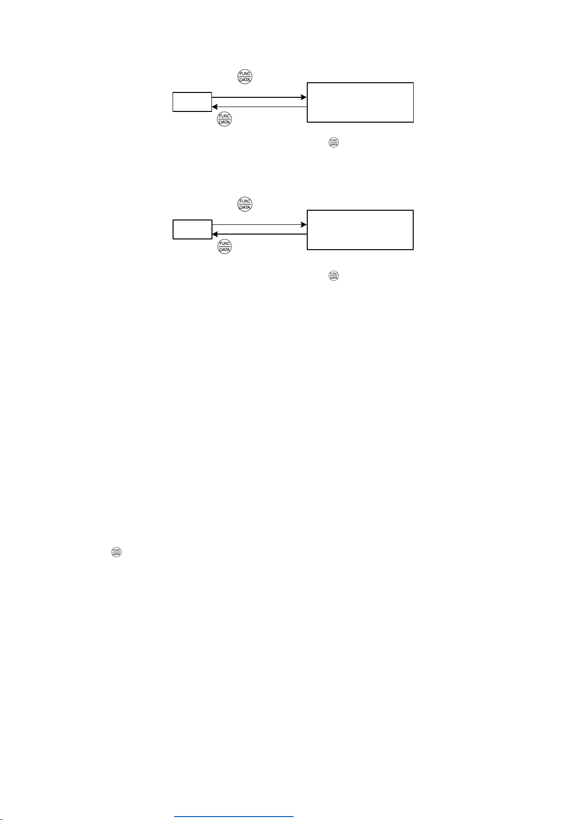
Table 1 shows the details of the data copying functions.
Table 1 List of Data Copying Functions
Display on
LED Monitor Function Description
read
Read data Reads the function code data out of the inverter’s memory and stores it into the keypad
memory.
Also reads out inverter’s current running status information which can be checked by
FRENIC Loader, such as information of I/O, system, alarm, and running status.
Pressing the key during a read operation (when
read
is blinking) immediately aborts
the operation and displays
err
(blinking).
If this happens, the entire contents of the memory of the keypad will be completely cleared.
copy
Write data Writes data stored in the keypad memory into the inverter’s memory.
If you press the key during a write operation (when
copy
is blinking), the write
operation that is under way will be aborted and
err
will appear (blinking).
If this happens, the contents of the inverter’s memory (i.e., function code data) have been
partly updated and remain partly old. Therefore, do not operate the inverter.
Instead, perform initialization or rewrite the entire data.
If this function does not work, refer to "If data copying does not work".
ueri
Verify data Verifies (collates) the data stored in the keypad memory with that in the inverter's
memory.
If any mismatch is detected, the verify operation will be aborted, with the function code in
disagreement displayed blinking. Pressing the key again causes the verification to
continue from the next function code.
Pressing the key during a verify operation (when
ueri
is blinking) immediately aborts
the operation and displays
err
(blinking).
err
appears blinking also when the keypad does not contain any valid data.
proT
Enable Data
protection
Enables the Data protection of data stored in the keypad’s memory.
In this state, you cannot read any data stored in the inverter’s memory, but can write
data into the memory and verify data in the memory.
Upon pressing the key the inverter immediately displays
err
.
chec
(*)
Read inverter
running
information
Reads out inverter’s current running status information that can be checked by
FRENIC Loader, such as information of I/O, system, alarm, and running status, excluding
function code data.
Use this command when the function code data saved in the PC should not be overwritten
and it is necessary to keep the previous data.
Pressing the key during a read operation (
chec
blinking) immediately aborts
the operation and displays
err
(blinking).
To get out of the error state indicated by a blinking
err
or
cper
, press the key.
When
cper
is blinking, it indicates that the function code number does not match. But in this case the function
codes which are consistent completely can continue copying after pressing key.
While
cper
is blinking, pressing key changes display to flashing of
err
.
(*)
A
ce(E2S) series of ROM version number less than 500 or Lift(LM2) series does not support “
chec
”.
Data protection
You can protect data saved in the keypad from unexpected modifications. Enabling the data protection that was disabled
changes the display
read
on the "Data Copying" function list to
proT
, and prohibits data reading from the inverter.
To enable or disable the data protection, follow the steps below.
(1) Select the "Data Copying" (
'cpy
) on the function selection menu in Programming mode.
(2) When the
'cpy
is displayed, holding the key down for at least 5 seconds alternates data protection status between
enabled or disabled.
For switching the data protection status, be sure to hold the key down for at least 5 seconds. Once the key is
released within 5 seconds, press the key to go back to the
' cpy
display and perform the keying operation
again.
Dealers Industrial Equipment -- Visit https://DealersElectric.com or call (908) 688-1966 for all of your electric motor & VFD needs!

INR-SI47-1246a
-6 -
• Disabling the enabled data protection
'cpy
read proT
(Displayed item changes.)
⇒
Hold key down
for at least 5 seconds.
While running the "Data Copying" (
'cpy
)function, holding down the key for 5 seconds or more displays
read
after
displaying
proT
for 5 seconds to complete disabling the data protection.
• Enabling the disabled data protection
'cpy
read
proT
(Displayed item changes.)
⇒
Hold key down
for at least 5 seconds.
While running the "Data Copying" (
'cpy
) function, holding down the key for 5 seconds or more displays
proT
after
displaying
read
for 5 seconds to complete enabling the data protection.
The followings are restrictions and special notes concerning "Data Copying."
If data copying does not work
Check whether
err
or
cper
is blinking.
(1) If
err
is blinking (a write error), any of the following problems has arisen:
• No data exists in the keypad memory. (No data read operation has been performed since shipment, or a data read
operation has been aborted.)
• Data stored in the keypad memory contains any error.
• The models of copy source and destination inverters are different.
• A data write operation has been performed while the inverter is running.
• The copy destination inverter is data-protected. (Function code F00 = 1)
• In the copy destination inverter, the "Enable write from keypad" command WE-KP is OFF.
• A Read data operation has been performed for the inverter whose data protection was enabled.
(2) If
cper
is blinking, any of the following problems has arisen:
• The function codes stored in the keypad and ones registered in the inverter are not compatible with each other. (Either of
the two may have been revised or upgraded in a non-standard or incompatible manner. Consult your Fuji Electric
representative.)
• If the inverter type is the same
cper
has occurs by the software versions mismatch.
Pressing key can continue copying. But added function codes according to upgrade can not be copied.
• If the inverter type is different or special products for special customers
Do not copy since the function codes are not compatible between inverters.
(3)
ercl
is blinking, when the mismatch of the number of function code for customizable logic occurs at
ueri
(Verify):
(FRENIC-Ace,VP or Lift series has
ercl
detecting function.)
• In FRENIC-Ace series,
ercl
is blinking if a customer will copy the function codes relating to customizable logic in an
inverter which has the ROM version number 300 or later (has function codes for 200 steps) to TP-E1U and verify whether
they matches the codes of another inverter which has the ROM version number less than 300 (has function codes for
100 steps) and vice versa. In FRENIC-VP or Lift series, it works similar behaviour regardless of the ROM version.
(4) Some models have the password function. If the password has been set, it prevents the copy operation.
For more information, please refer to the instruction manual or user's manual for an each model.
Dealers Industrial Equipment -- Visit https://DealersElectric.com or call (908) 688-1966 for all of your electric motor & VFD needs!

INR-SI47-1246a
- 7 -
(4) USB Connectivity
The keypad has a USB port (mini B connector) on its face. To connect a USB cable, open the USB port cover as shown
below.
Connecting the inverter to a PC with a USB cable enables remote control from FRENIC Loader. On the PC running
FRENIC Loader, it is possible to edit, check, manage, and monitor the function code data in real-time, to start or stop the
inverter, and to monitor the running or alarm status of the inverter.
Do not connect or disconnect the USB cable to the USB port on the keypad during the data copying.
For the instructions on how to use the FRENIC Loader, refer to the FRENIC Loader Instruction Manual(INR-SI47-1526□,
INR-SI47-1549□-E).
Dealers Industrial Equipment -- Visit https://DealersElectric.com or call (908) 688-1966 for all of your electric motor & VFD needs!

INR-SI47-1246a
-8 -
Fuji Electric Co., Ltd.
Gate City Ohsaki, East Tower, 11-2, Osaki 1-chome, Shinagawa-ku, Tokyo, 141-0032, Japan
Phone: +81 3 5435 7058 Fax: +81 3 5435 7420
URL http://www.fujielectric.com/
Dealers Industrial Equipment -- Visit https://DealersElectric.com or call (908) 688-1966 for all of your electric motor & VFD needs!
Table of contents
Other FE Keypad manuals