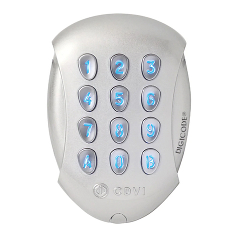
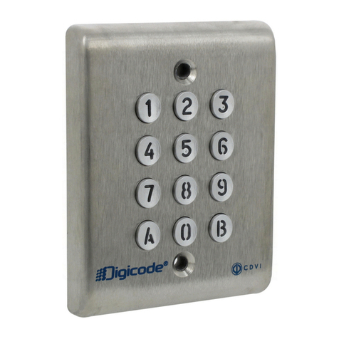
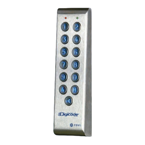
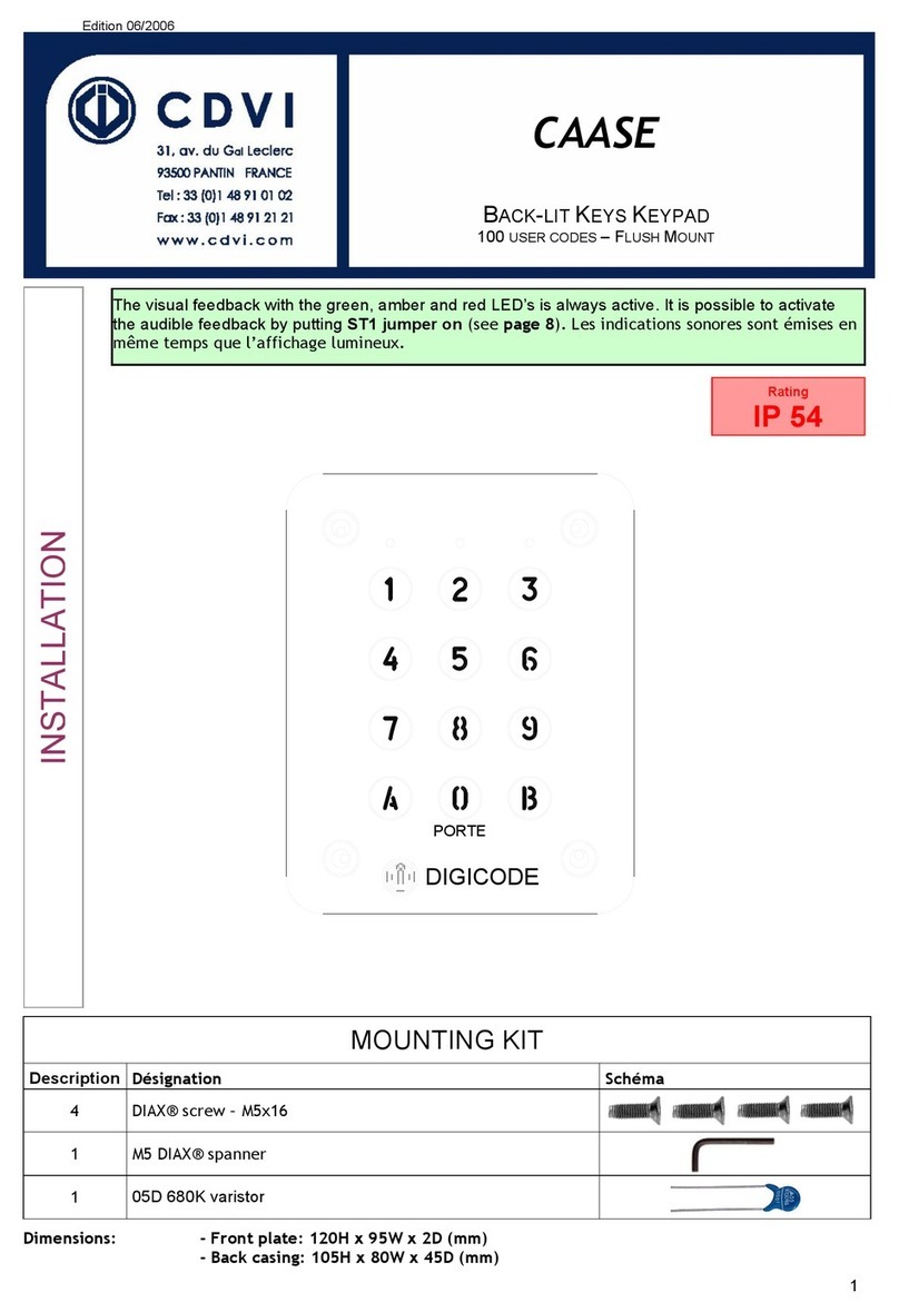
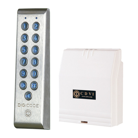
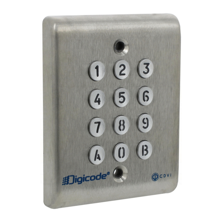
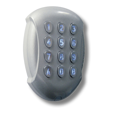
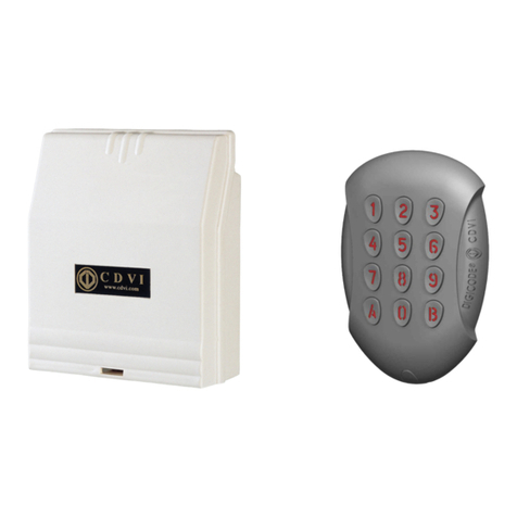
CDVI Galeo User manual

GALEO®
Group Company
INSTALLATION MANUAL
Illuminated Weatherproof Keypad
Range: Digicode®/
MANUEL D’INSTALLATION
Clavier codé rétro-éclairé étanche
Gamme: Digicode®

75
15 110
1] GENERAL INFORMATION
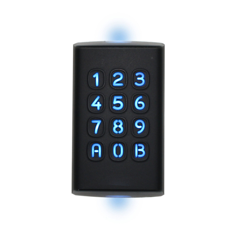
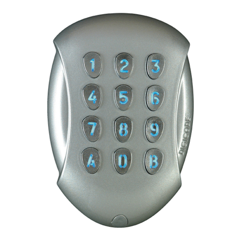
The GALEO keypad has a remote electronics
and was designed to operate from 12 to 24 VAC
and from 12 to 48 VDC. Its robustness,
its reliability and its design makes it ideal
for those environments, which require low
to medium access control of single door.
The GALEO is suitable for gates, garage doors,
residential commercial and industrial buildings.
Specifications
Construction: Zamak®(polish cast aluminium).
Capacity of 100 user codes of 4 to 5 digits.
Stored in non-volatile EPROM memory.
Buzzer audible signal.
12-backlit keys.
Illumination mode
permanent or timed.
HIGH RESISTANCE TO VANDALISM (HRV).
Completely sealed (filled with epoxy)
Remote controller (in plastic enclosure).
3 core cable wiring between keypad
and remote controller.
Master code and the User codes can be of 4
or 5-digit in length
.
1 output: 8A at 250V relay.
Adjustable time output : 1 to 99 seconds,
select 00 for toggle mode.
Request-to-Exit input.
Operating voltage: 12 to 24V AC and 12 to 48V DC.
Consumption (when 3 relay outputs activated.
and keypad illuminated):
- 12V AC: Standby 90mA
- 24V AC: Standby 46mA
- 12V DC: Standby 100mA
- 24V DC: Standby 55mA
- 48V DC: Standby 30mA
Optional: Galeo 2R: 2 relay outpouts
Galeo 3R: 3 relay outpouts
Galeo®remote controller
-25°C to +70°C
Marin grade Zamak® keypad
Rating IP64
Certification CE
147
124 55
-20°C to +70°C
Rating IP52
Certification CE
Certification FCC CFR
47 Part 15 compliance
Certification R&TTE
2www.cdvi.com
www.cdvigroup.com
GALEO
Illuminated Weatherproof Keypad with remote electronics
INSTALLATION MANUEL
HIGH RESISTANCE
TO VANDALISM

3] MOUNTING KIT
3] MOUNTING KIT
2] NOTES & RECOMMENDATIONS
Cable
The distance between the GALEO and the remote
electronic can not exceed more than 10 meters.
Make sure that the cable is not near by a high
voltage cables (ex: 230 V AC).
Recommended cable between
the GALEO and the remote electronic
2 twisted pairs (4 wires) SYT1 0.8MM.
Recommended power supplies
suitable for the GALEO
(for more information visit our web site
at www.cdvi.com):
- ARD12 (230V input)
- BS60 (230V input)
Mounting recommendations
Mount the keypad on a flat surface to avoid
any vandalism and to insure the best mounting.
Security advice
For security advice reasons, change
the factory default master code.
When selecting a master code and user code
avoid simple codes (example : 3 4 5 6 7).
Back EMF protection
To secure the system from back electromagnetic
fields do not forget to mount the varistor
in parallel on the lock.
Varistor
GALEO 111222--
REMOTE
CONTROLLER ----2221
(M4x10)
Torx®
screw)
T20 Torx®
Spanner Caps (M4x30)
mounting
screws
Plastic
anchors Wiring
sealed caps
Mounting
plate for
remote
electronic
box
3
www.cdvi.com
www.cdvigroup.com
GALEO
Illuminated Weatherproof Keypad with remote electronics
INSTALLATION MANUEL

1
4
GALEO
®
2
5
GALEO
®
3
(x2)
6
4] MOUNTING INSTRUCTIONS
Once you have made sure that the mounting kit is complete and that you prepared
the cables of the GALEO keypad and of its remote electronic then you can proceed
and mount the product. Make sure that you have all the appropriate tools
(drill, screw drivers and a meter tape...) and follow the mounting instructions
of for the GALEO keypad and for the remote electronic.
Verify the distance between the
GALEO®keypad and its remote
electronic(refertopage3´Notes
and Recommendations). Place
the back plate of the GALEO®on
the wall and the bracket of the
remote electronic then mark
with a pen the hole location
then drill the 2 mounting holes
(drill bit ÿ 5 mm and 35 MM
hole depth) and the hole wiring
access.
Fasten the GALEOÆ keypad to the
back plate by using the supplied
(M4x10) Torx screw and T20 Trox
spanner hardware. Place the screw
cap at the bottom of the keypad.
Insert the 2 plastic anchors in
the holes. Place the back plate
of the GALEO®and screw on the
wall using the supplied (M4x30)
mounting screws.
Insert the 2 plastic anchors in the
holes. Place the bracket of the
remote electronic and screw on
the wall using the supplied M4x30
screws. Slide the box from up to
down on the bracket.
Insert the cable in the hole
access area of the back plate.
then mount the keypad on the
back plate, placing first the
top in the hooks and then the
bottom.
Insert the cable in the remote
electronic and wire the cable to
the terminals. Donít forget to ins-
tall the varistor on the lock (refer
to page 3 ´Notes and Recommen-
dations‘).
4www.cdvi.com
www.cdvigroup.com
GALEO
Illuminated Weatherproof Keypad with remote electronics
INSTALLATION MANUEL

VV
R1
P3 P2
C1 T1 P1 M P2 PX H H + - E
P1 H
V
VV
5] WIRING DIAGRAM GALEO®1 RELAY OUTPUT
Terminals : Remote controller
V Input voltage 12V to 24VAC or 12V to 48VDC
R1 N/C contact relay 1
C1 Common relay 1
T1 N/O contact relay 1
P1 Request-to-exit input relay 1
M Common of input
H Timer Contact
+White cable keypad
-Brown cable keypad
E Green or Blue cable (illumination)
D - 693 : Remote controller
P3 jumper allows
to the user to modify
its own Pin code.
To enable this feature put
the jumper on.
(see Programming section
in the instruction manual)
P2 jumper resets to factory
default values the keypad.
Remove the power
from the keypad
then put the jumper
(see Programming section
in the instruction manual)
Input voltage
12 to 24VAC
or 12 to 48VDC
Fail safe lock H (Open)
Keypad mode
H (Close)
Request-to-Enter mode
Relay 1
White
Brown
Green or blue
Fail secure lock
Varistor
Power supply
According to lock
specifications
Request-to-Exit inputs
P1 request-to-exit input activates relay 1.
P2 request-to-exit input activates relay 2.
Latch or toggled output.
H input can be used with a timer
to enable free access by pressing
on any digit key on the keypad.
When the contact is open
then the request-to-enter is disabled.
When the contact is closed then press
any key on the keypad to enter.
5
www.cdvi.com
www.cdvigroup.com
GALEO
Illuminated Weatherproof Keypad with remote electronics
INSTALLATION MANUEL

VV
R1
P3 P2
C1 T1 R2 C2 T2 P1 M P2 PX H H + - E
P1 H
V
V
V
P2
6] WIRING DIAGRAM GALEO®2 RELAY OUTPUTS
Terminal : Remote controller
V Input voltage 12V to 24VAC or 12V to 48VDC
R1 N/C contact relay 1
C1 Common relay 1
T1 N/O contact relay 1
R2 N/C contact relay 2
C2 Common relay 2
T2 N/O contact relay 2
P1 Request-to-exit input relay 1
M Common of inputs
P2 Request-to-exit input relay 2
H Timer Contact
+ White cable from keypad
-Brown cable from keypad
EGreen or Blue cable (illumination)
Request-to-Exit inputs
P1 request-to-exit input activates relay 1.
P2 request-to-exit input activates relay 2.
Latch or toggled output.
H input can be used with a timer
to enable free access by pressing
on any digit key on the keypad.
When the contact is open
then the request-to-enter is disabled.
When the contact is closed then press
any key on the keypad to enter.
D - 693 : Remote controller
P3 jumper allows
to the user to modify
its own Pin code.
To enable this feature put
the jumper on.
(see Programming section
in the instruction manual)
P2 jumper resets to factory
default values the keypad.
Remove the power
from the keypad
then put the jumper
(see Programming section
in the instruction manual)
6www.cdvi.com
www.cdvigroup.com
GALEO
Illuminated Weatherproof Keypad with remote electronics
INSTALLATION MANUEL
Input voltage
12 to 24VAC
or 12 to 48VDC
Fail safe lock H (Open)
Keypad mode
H (Close)
Request-to-Enter mode
Relay 1 Relay 2
White
Brown
Green or blue
Fail secure lock
Varistor
Power supply
According to lock
specifications

VV
R1
P3 P2
C1 T1 R2 C2 T2 R3 C3 T3 P1 M P2 PX H H + - E
P1 P2 H
V
VVV
D - 693 : Remote controller
P3 jumper allows
to the user to modify
its own Pin code.
To enable this feature put
the jumper on.
(see Programming section
in the instruction manual)
P2 jumper resets to factory
default values the keypad.
Remove the power
from the keypad
then put the jumper
(see Programming section
in the instruction manual)
7] WIRING DIAGRAM GALEO®3 RELAY OUTPUTS
Terminal : Remote controller
V
Input voltage
12V to 24VAC or 12V to 48VDC
V
Input voltage
12V to 24VAC or 12V to 48VDC
R1 N/C contact relay 1
C1 Common relay 1
T1 N/O contact relay 1
R2 N/C contact relay 2
C2 Common relay 2
T2 N/O contact relay 2
R3 N/C contact relay 3
C3 Common relay 3
T3 N/O contact relay 3
P1 Request-to-exit input relay 1
M Common of inputs
P2 Request-to-exit input relay 2
H
Timer Contact
+ White cable from keypad
-
Brown cable from keypad
E
Green or Blue cable (illumination)
Request-to-Exit inputs
P1 request-to-exit input activates relay 1.
P2 request-to-exit input activates relay 2.
Latch or toggled output.
H input can be used with a timer to
enable free access by pressing on any
digit key on the keypad.
When the contact is open
then the request-to-enter is disabled.
When the contact is closed then press any key on
the keypad to enter.
7
www.cdvi.com
www.cdvigroup.com
GALEO
Illuminated Weatherproof Keypad with remote electronics
INSTALLATION MANUEL
Input voltage
12 to 24VAC
or 12 to 48VDC
Fail safe lock H (Open)
Keypad mode
H (Close)
Request-to-
Enter mode
Relay 1 Relay 2 Relay 3
White
Brown
Green or blue
Fail secure lock
Varistor
Power supply
According to lock
specifications

8] PROGRAMMING CHART
Enter Master code
Enter Master code
twice
twice
1 x beep
1 x beep
1 x beep
1 x beep
1 x beep
1 x beep
1 x beep
1 x beep
1 x beep
1 x beep
1 x beep
1 x beep
1 x beep
1 x beep
=
=
OK
OK
4 beeps
4 beeps
=
=
error
error
1 x beep
1 x beep
=
=
OK
OK
4 beeps
4 beeps
=
=
error
error
1 x beep
1 x beep
=
=
OK
OK
4 beeps
4 beeps
=
=
error
error
1 x beep
1 x beep
=
=
OK
OK
4 beeps
4 beeps
=
=
error
error
1 x beep
1 x beep
=
=
OK
OK
4 beeps
4 beeps
=
=
error
error
1 x beep
1 x beep
=
=
OK
OK
4 beeps
4 beeps
=
=
error
error
A0
A0
A1
A1
A2
A2
A3
A3
A4
A4
A5
A5
10-99 sec
00 =
permanent
01-99 sec
00 = toggled
01-99 sec
00 = toggled
01-99 sec
00 = toggled
4’ or 5’
digits Change
master code
Press B to exit from
programming
2 beeps
2 x beeps
2 x beeps
10=Default 01=Default 01=Default 01=Default 5= Default
12345=
Default
Master code
Galeo 2 R
Galeo 2 R
Galeo 3 R
Galeo 3 R
Illumination
duration Time Relay 1 Time Relay 2 Time Relay 3 Code length
8www.cdvi.com
www.cdvigroup.com
GALEO
Illuminated Weatherproof Keypad with remote electronics
INSTALLATION MANUEL

9
www.cdvi.com
www.cdvigroup.com
1 x beep
1 x beep
1 x beep
1 x beep
1 x beep
1 x beep
1 x beep
1 x beep
1 x beep
1 x beep
1 x beep
1 x beep
=
=
OK
OK
4 beeps
4 beeps
=
=
error
error
1 x beep
1 x beep
=
=
OK
OK
4 beeps
4 beeps
=
=
error
error
1 x beep
1 x beep
=
=
OK
OK
4 beeps
4 beeps
=
=
error
error
1 x beep
1 x beep
=
=
OK
OK
4 beeps
4 beeps
=
=
error
error
1 x beep = ok
1 x beep = ok
A6
A6
A7
A7
A8
A8
A9
A9
AA
AA
00-99
00-99
2
digits 2
digits 2
digits 4 beeps = user location:
“used”
1 bips = user location: “free”
4’ or 5’ digit code
Press A
Then B
2 Beeps are
emitted
AB=default 13=default 46=default
0=buzzer
disabled
1 = buzzer
enabled
Reset Sub master
code Sub master
code 2 Sub master
code 3
Buzzer
(audible
feedback) User codes
Galeo 2
Galeo 2
Galeo 3
Galeo 3
GALEO
Illuminated Weatherproof Keypad with remote electronics
INSTALLATION MANUEL

5] PROGRAMMATION
5] PROGRAMMATION
A. TIME OUTPUTS
This section allows to program the bac
klighting time and the Relay activation time
1. Enter the master code twice
(12345 default value master code).
2 beeps are emitted to confirm
entry in programming mode.
2. Enter A6 to program the key-in
keypad time and the keys lit time.
1 beep is emitted. Enter the time in 10th
of second – 10 for 10 seconds up to 99
for 99 seconds the backlighting dims
10 seconds after the last keypress
or switches off after entering a valid code.
Enter 00 for permanent illumination keys.
One beep is emitted to validate the time.
3. Enter A1 to program relay 1
output time (door release time).
1 beep is emitted. For a latched output
enter the time in seconds – 01 for 1
second up to 99 for 99 seconds.
Enter 00 for a toggled output.
One beep is emitted to validate the time.
4. Press B to exit from
programming mode.
2 beeps are emitted to confirm that the
keypad is in stand-by operating mode.
4 beeps indicate a data
computing error.
B. SETTING CODE LENGTH
1. Enter the master code twice
(12345 default value master code).
2 beeps are emitted to confirm
entry in programming mode.
2. Enter A4 to program the code length.
One beep is emitted. Enter 4 or 5
for the digit code. One beep is emitted
to confirm programming of the code length.
3. Enter A5 to modify the master code.
One beep is emitted. Enter the new 4
or 5-digit master code. One beep is
emitted to confirm programming
of the newmaster code.
4. Press B to exit from
programming mode.
2 beeps are emitted to confirm that the
keypad is in stand-by operating mode.
4 beeps indicate a data computing error.
C. CHANGING THE MASTER CODE
The master code is used only to
enter in programming mode
1. Enter the master code twice
(12345 default value master code).
2 beeps are emitted to confirm
entry in programming mode.
Default values
- Without codes.
- Illumination time: 10 seconds.
- Relay release time: 1 second.
- Code length: 5-digit.
- Master Code: 12345.
- Programming security time
:
120 secondes.
- Code length for sub master code:
Version 1 relay (Group 1) = A and B,
Version 2 relays (Group 2) = 1 and 3
Version 3 relays (Group 3) = 4 and 6.
Audible signal:
The buzzer indicates different audible
signals. It can be turned off by cutting
the ST1 wire on the remote controller
1 short beep: Keypad powered
1 long beep: data computing in
programming or access granted
2 short beeps: Enter or Exit from
programming
4 short beeps: data computing error
Code length
The master code and the User codes can
be of 4 or 5-digit in length.
All the keypad keys can be used to
program a code. The master code and the
Pin code can be of 4 or 5-digit code. The
master code CAN NOT be used as a PIN
code (User Pin code). Codes 00000 and
0000 can only be used to delete a user Pin
code. To delete a specific User pin Code
replace it by 0000 if code length is 4-digit
format or replace it by 00000 if the code is
in 5-digit format.
P2 jumper:
Reset master code
and user codes
P3 jumper:
modification of individual
code by the user
GALEO
Illuminated Weatherproof Keypad with remote electronics
INSTALLATION MANUEL
10
www.cdvi.com
www.cdvigroup.com
2. Enter A5 to modify the master code.
One beep is emitted. Enter the new 4
or 5-digit master. One beep is emitted
to confirm that the master code
is programmed.
3. Press B to exit from the
programming mode.
2 beeps are emitted to confirm that the
keypad is in stand-by operating mode.
D. RESET MASTER CODE
AND USER CODES
1. Enter the master code twice
(12345 default value master code).
2 beeps are emitted to confirm
entry in programming mode.
2. Enter A6 to reset the Master Code
and the User codes.
One beep is emitted. Press on A
and B to confirm reset of all memory
of the keypad. Wait for two beeps.
The master code is restored
to its default value 12345
and all the User codes are deleted
from the keypad. Once the reset
is completed then the keypad returns
to a stand-by operating mode.
OR
1. Cut the power. Put the jumper on P2.
2. Put the power back. Wait approxi
mately 3 seconds.
Two beeps are emitted to confirm reset
of the keypad. Remove P2 jumper.
The master code is restored to its default
value 12345 and all the User
codes are deleted from the keypad.
E. RESET MASTER CODE
On stand-by operating mode,
put a jumper on P2.
Wait 1 second and then remove
the jumper. One beep is emitted.
The master code is restored
to its default value 12345 in 5-digit
code and 1234 in 4-digit code.
F.
SETTING A SUB MASTER CODE
The Sub Master code allows the user
to change its own code without entering
in programming mode. For security
reasons the code need to be changed
periodically. This feature makes it easier
and faster to change its code.
1. Enter the master code twice
(12345 default value master code).
2 beeps are emitted to confirm entry
in programming mode.
2. Enter A7 to program a sub master
code for the user individual Pin
code modification.
One beep is emitted. Enter the new
2-digit sub master code. One beep
is emitted to confirm programming
of the sub master code.
3. Press B to exit from
the programming mode.
2 beeps are emitted to confirm
that the keypad is in stand-by
operating mode.
G. ADDING, CHANGING
OR DELETING A USER CODE
Group 1: from address 00 to address 99,
relay output 1
1. Enter the master code twice
(12345 default value master code).
2 beeps are emitted to confirm entry
in programming mode.
2. To add a user code, enter the user
location (from 00 to 99).
If the user location is free 1 beep
is emitted, enter the 4 or 5-digit
User code.
3. To Change a User code enter
the user location.
4 beeps are emitted to indicate that
user location is already programmed.
Enter a new 4 or 5-digit code.
A beep is emitted to confirm the new
user code.
GALEO
Illuminated Weatherproof Keypad with remote electronics
INSTALLATION MANUEL
11 www.cdvi.com
www.cdvigroup.com

4. To delete a User code enter
the user location.
4 beeps are emitted.
Enter 00000 in 5-digit length code
or 0000 in 4-digit length code.
A beep is emitted to confirm the new
user code.
NOTE: If the Pin code is already programmed
or is identical to the master code,
then 4 beeps are emitted.
Press B to exit from the programming
mode. 2 beeps are emitted to confirm
that the keypad is in stand-by
operating mode.
H. CHANGING THE CODE
BY A USER
To authorize a user to modify its own
User code put a jumper on P3
(to disable the feature remove the jumper).
1. Enter the old user code.
The relay is activated and a beep
is emitted.
2. Enter the 2-digit sub master code
(default sub master code A and B).
A beep is emitted to authorise
the modification.
3. Enter the new user code.
2 beeps are emitted to confirm
the new code.
4. Check the new user code to be sure
of the modification.
I. Audible Feedback
The audible signal is enabled
in programming mode
and when the relay is energised
after a valid code.
To enable the audible feedback
on a key press:
1. Enter the master code twice
(12345 default value master code).
2 beeps are emitted to confirm entry
in programming mode.
2. Press AA.
One beep is emitted. Press 0 to disable
the audible signal during a keypress.
Press 1 to enable the audible signal
during a keypress. One beep confirms
the new setting.
3. Press B to exit from programming.
2 beeps are emitted to confirm exit
from programming mode.
J. OPTIONAL GALEO 2 AND GALEO 3
PROGRAMMING INSTRUCTION
Programming instructions are the same
as for the GALEO keypad with 1
relay output.
GALEO 2: 2 relay outputs N/O and N/C
contacts 8A @ 250V~
contacts 8A @ 250V~
Group 1: from user location 00 to user
location 59 to activate relay 1
Group 2: from user location 60 to user
location 99 to activate relay 2
Release Time of relay2 enter A2
sub master code enter A8
(default values 1 and 3).
GALEO 3: 3 relay outputs N/O and N/C
contacts 8A @ 250V~
contacts 8A @ 250V~
Group 1: from user location 00 to user
location 59 to activate relay 1
Group 2: from user location 60 to user
location 79 to activate relay 2
Group 3: from user location 80 to user
location 99 to activate relay 3
Release time for relay 3 enter A3
sub master code enter A9
(default values 4 and 6).
12 www.cdvi.com
www.cdvigroup.com
GALEO
Illuminated Weatherproof Keypad with remote electronics
INSTALLATION MANUEL

To program Pin codes:
User
location Code Name
00
01
02
03
04
05
06
07
08
09
10
11
12
13
14
15
16
17
18
19
20
21
22
23
24
25
26
27
28
29
30
31
32
33
User
location Code Name
34
35
36
37
38
39
40
41
42
43
44
45
46
47
48
49
50
51
52
53
54
55
56
57
58
59
60
61
62
63
64
65
66
67
User
location Code Name
68
69
70
71
72
73
74
75
76
77
78
79
80
81
82
83
84
85
86
87
88
89
90
91
92
93
94
95
96
97
98
99
GALEO®Relay 1(1 output)
Relay 1 : From user location 00
to 99.
GALEO®Relays 2 (2 output)
Relay 1 : From 00 to 59,
Relay 2 : From 60 to 99.
GALEO®Relays 3 (3 outputs)
Relay 1 : From 00 to 59,
Relay 2 : From 60 to 79,
Relay 3 : From 80 to 99.
13
www.cdvi.com
www.cdvigroup.com
GALEO
Illuminated Weatherproof Keypad with remote electronics
INSTALLATION MANUEL

75
15 110
1] PRESENTATION DU PRODUIT
Le GALEO est un clavier codé avec électronique
déportée(fournie),delamarqueDigicode®.Equipé
en standard, d’un concept électronique, le GALEO
peut fonctionné du 12 V au 24 V, alternatif ou du
12 V au 48 V, continu. Sa robustesse, sa compacité
etsondesignpermettentuneintégrationduGALEO
surtouslessitesdelacollectivité(ouvertured’accès
de résidence) ou des particuliers (commande de
portails et portes de garage automatiques).
Caractéristiques techniques
Matière : (corps et touches) ZAMAK®.
100 codes programmables.
Sauvegarde mémoire permanente E2PROM.
Interaction : Buzzer.
Clavier 12 touches.
Choix du mode d’éclairage :
Permanent ou sur impulsion.
Haute Résistance au Vandalisme (HRV).
Étanchéité totale (surmoulé).
Électronique déportée (fourni en boîtier).
Liaison entre le Digicode®et l’électronique :
3 fils.
Nombre de terme des codes Maître et Résidents :
4 ou 5.
Sortie de 1 à 3 relais (selon les versions).
Relais temporisables : 1 à 99 secondes.
Programmation et utilisation guidées
par signal sonore intégré.
Mode bistable possible.
Carte électronique : 1, 2 et 3 relais.
Possibilité d’associer un bouton poussoir
de sortie commandant l’ouverture de l’accès
Alimentation : 12 V à 24 V en alternatif
et 12 V à 48 V en continu.
Consommation (3 relais commandés + clavier) :
- En 12 V AC : Au repos 90 mA,
- En 24 V AC : Au repos 46 mA,
- En 12 V DC : Au repos 100 mA,
- En 24 V DC : Au repos 55 mA,
- En 48 V DC : Au repos 30 mA.
Electronique déportée, fournie
avec le clavier codé GALEO…
-25° C à +70°C
Résistant à un environnement marin
Indice de protection IP64
Certification CE
147
124 55
-20° C à +70°C
Indice de protection IP52
Certification CE
Certification FCC CFR
47 Part 15 compliance
Certification R&TTE
14 www.cdvi.com
www.cdvigroup.com
GALEO
Clavier codé rétro-éclairé à électronique déportée
MANUEL D’INSTALLATION
HAUTE RESISTANCE
AU VANDALISME

3] KIT DE MONTAGE
3] KIT DE MONTAGE
2] RAPPELS ET RECOMMANDATIONS
Rappel de câblage
La distance de câblage entre le GALEO
et l’électronique déportée doit être au maximum
de 10 m.
Attention de ne pas passer vos fils
à proximité de câbles «Courant fort»
(ex: 230 V AC).
Câbles préconisés entre le GALEO
et l’électronique déportée
Câbles 2 paires (4 fils) SYT1 8/10ème.
Alimentations préconisées
Il existe deux alimentations adaptées pour
le clavier codé GALEO (Voir www.cdvi.com) :
- ARD12
- BS60
Montage
Afin d’optimiser la fixation du GALEO
et de prévenir les tentatives d’arrachage,
privilégiez les surfaces planes.
Composition des codes
Par soucis de sécurité, veillez à modifier le code
maître usine par celui de votre choix.
Lors du changement du code maître usine et
de la création des codes utilisateurs, évitez les
codes trop simples (ex: les suites 3 4 5 6 7).
Recommandations d’installation
Pour sécuriser l’installation, n’oubliez pas
de placer la varistance sur le système de
verrouillage, en parallèle, au niveau
de l’alimentation.
L’électronique déportée du
GALEO doit être impérativement installée dans un
environnement
clos et protégée des conditions
climatiques extérieures.
Varistance
GALEO 111222--
Electronique
déportée ----2221
Vis Torx®
à tête
fraisée
(M4x10)
Clé mâle
coudée
pour vis
Torx®
(T20)
Cache vis
Vis
cruciforme
à tête
fraisée
(M4x30)
Cheville
plastique Passe fil
Plaque de
fixation de
l’électronique
déportée
15
www.cdvi.com
www.cdvigroup.com
GALEO
Clavier codé rétro-éclairé à électronique déportée
MANUEL D’INSTALLATION

1
4
GALEO
®
2
5
GALEO
®
3
(x2)
6
4] MONTAGE
Après avoir vérifié que le kit de montage est complet et opéré le raccordement du clavier
codé GALEO et de son électronique déportée, vous allez pouvoir procéder à l’installation
finale du produit. Réunissez le matériel approprié (Perçeuse, tournevis, mètre,...)
et suivez les recommandations de montage du GALEO et de son électronique déportée.
Vérifiez la distance entre le GA-
LEO®
et son
électronique dépor-
tée (Voir page 3 «Rappels
et
préconisations»). A l’aide de la
plaque de fixation de l’électro-
nique déportée et du GALEO®,
pre
nez les marques et percez les
2 trous de fixation (forêt Ø 5 mm
et profondeur minimum. = 35 mm)
ainsi que l’ouverture pour le
passage du câble électrique
destiné au clavier.
Bloquez le GALEO®sur son support
par l’intermédiaire de la vis TORX®
et de son outil spécifique (clé
mâle coudée). Pour finaliser le
montage de ce produit, placez le
cache-vis.
Positionnez les 2 chevilles plasti-
ques dans les trous. Puis Fixez le
fond du GALEO
®
sur le support de
votre choix, à l’aide des vis cruci-
formes à têtes fraisées.
Positionnez les 2 chevilles plasti-
que dans les trous. Puis fixez la
plaque de fixation de l’électronique
déportée sur la surface de votre
choix, à l’aide des vis cruciformes
à têtes fraisées. Venez ensuite
placer l’électronique déportée sur
son support.
Passez le câble électrique du GALEO®
dans son ouverture et fixez le à
son support par le haut avec le
crochet supérieur.
Passez vos fils, glissez les passe-
fils de l’électronique déportée et
faites vos branchements. Lors de
cette opération, n’oubliez pas de
placer la varistance (Voir page 3
«Rappels et préconisations»).
16 www.cdvi.com
www.cdvigroup.com
GALEO
Clavier codé rétro-éclairé à électronique déportée
MANUEL D’INSTALLATION

VV
R1
P3 P2
C1 T1 P1 M P2 PX H H + - E
P1 H
V
VV
5] SCHÉMA DE RACCORDEMENTS GALEO 1 RELAIS
Bornier : Electronique déportée
V Alimentation 12V à 24V AC ou 12V à 48V DC
R1 Contact repos du relais 1
C1 Commun du relais 1
T1 Contact travail du relais 1
P1 Bouton intérieur de sortie relais 1
M Commun bouton
H Contact horloge
+Clavier fil blanc
-Clavier fil marron
E Clavier vert ou bleu ( éclairage )
D - 693 : Electronique déportée
Le cavalier sur P3
permet de changer
le code d’entrée par
l’utilisateur. Le cavalier
doit être placé pour les
modifications et enlevé
pour verrouiller cette
option. (voir chapitre
«Programmation»)
Le cavalier sur P2 permet
de réaliser une remise
à zéro de la mémoire.
Le cavalier doit être placé
hors tension pour que la
manipulation fonctionne
(voir chapitre «Program-
mation»)
Alimentation
12 à 24 V AC
ou 12 à 48 V DC
Gâche à rupture H (Ouvert)
GALEO en fonction clavier codé
H (Fermé)
GALEO en fonction
Bouton Poussoir
Relais 1
Blanc
Marron
Vert ou bleu
Gâche à émission
Varistance
Alimentation
côté puissance
de commande
Commande par bouton poussoir
Le raccordement du bouton poussoir P1 est
prévu pour commander le relais 1. Le mode
et la temporisation sont programmables.
Le contact horloge H permet
l’utilisation de toutes les touches
comme bouton extérieur.
Si le contact horloge est ouvert, les touches
sont utilisées comme des termes habituels.
Si le contact horloge est fermé, toutes les
touches sont utilisées pour l’ouverture libre.
17
www.cdvi.com
www.cdvigroup.com
GALEO
Clavier codé rétro-éclairé à électronique déportée
MANUEL D’INSTALLATION

VV
R1
P3 P2
C1 T1 R2 C2 T2 P1 M P2 PX H H + - E
P1 H
V
V
V
P2
6] SCHÉMA DE RACCORDEMENTS GALEO 2 RELAIS
Bornier : Electronique déportée
V Alimentation 12V à 24V AC ou 12V à 48V DC
R1 Contact repos du relais 1
C1 Commun du relais 1
T1 Contact travail du relais 1
R2 Contact repos du relais 2
C2 Commun du relais 2
T2 Contact travail du relais 2
P1 Bouton intérieur de sortie relais 1
M Commun boutons
P2 Bouton intérieur de sortie relais 2
H Contact horloge
+ Clavier fil blanc
-Clavier fil marron
EClavier vert ou bleu ( éclairage )
Commande par bouton poussoir
Le raccordement du bouton poussoir P1 est
prévu pour commander le relais 1. Le rac-
cordement du bouton poussoir P2 est prévu
pour commander le relais 2. Le mode et la
temporisation sont programmables.
Le contact horloge H permet l’utilisa-
tion de toutes les touches comme bou-
ton extérieur.
Si le contact horloge est ouvert, les touches
sont utilisées comme des termes habituels.
Si le contact horloge est fermé, toutes les
touches sont utilisées pour l’ouverture libre.
D - 693 : Electronique déportée
Le cavalier sur P3
permet de changer
le code d’entrée par
l’utilisateur. Le cavalier
doit être placé pour les
modifications et enlevé
pour verrouiller cette
option. (voir chapitre
«Programmation»)
Le cavalier sur P2 permet
de réaliser une remise
à zéro de la mémoire.
Le cavalier doit être placé
hors tension pour que la
manipulation fonctionne
(voir chapitre «Program-
mation»)
18 www.cdvi.com
www.cdvigroup.com
GALEO
Clavier codé rétro-éclairé à électronique déportée
MANUEL D’INSTALLATION
Alimentation
12 à 24 V AC
ou 12 à 48 V DC
Gâche à rupture
(Contact au repos)
H (Ouvert)
GALEO en fonction clavier codé
H (Fermé)
GALEO en fonction
Bouton Poussoir
Relais 1 Relais 2
Blanc
Marron
Vert ou bleu
Gâche à émission
Varistance
Alimentation
côté puissance
de commande

VV
R1
P3 P2
C1 T1 R2 C2 T2 R3 C3 T3 P1 M P2 PX H H + - E
P1 P2 H
V
VVV
D - 693 : Electronique déportée
Le cavalier sur P3
permet de changer
le code d’entrée par
l’utilisateur. Le cavalier
doit être placé pour les
modifications et enlevé
pour verrouiller cette
option. (voir chapitre
«Programmation»)
Le cavalier sur P2 permet
de réaliser une remise
à zéro de la mémoire.
Le cavalier doit être placé
hors tension pour que la
manipulation fonctionne
(voir chapitre «Program-
mation»)
7] SCHÉMA DE RACCORDEMENTS GALEO 3 RELAIS
Bornier : Electronique déportée
V Alimentation 12V à 24V AC ou 12V à 48V DC
R1 Contact repos du relais 1
C1 Commun du relais 1
T1 Contact travail du relais 1
R2 Contact repos du relais 2
C2 Commun du relais 2
T2 Contact travail du relais 2
R3 Contact repos du relais 3
C3 Commun du relais 3
T3 Contact travail du relais 3
P1 Bouton intérieur de sortie relais 1
M Commun boutons
P2 Bouton intérieur de sortie relais 2
H Contact horloge
+ Clavier fil blanc
-Clavier fil marron
EClavier vert ou bleu ( éclairage )
Commande par bouton poussoir
Le raccordement du bouton poussoir P1 est prévu
pour commander le relais 1. Le raccordement du
bouton poussoir P2 est prévu pour commander
le relais 2. Le mode et la temporisation sont pro-
grammables.
Le contact horloge H permet l’utilisation de
toutes les touches comme bouton extérieur.
Si le contact horloge est ouvert, les touches sont
utilisées comme des termes habituels. Si le contact
horloge est fermé, toutes les touches sont utilisées
pour l’ouverture libre.
19
www.cdvi.com
www.cdvigroup.com
GALEO
Clavier codé rétro-éclairé à électronique déportée
MANUEL D’INSTALLATION
Alimentation
12 à 24 V AC
ou 12 à 48 V DC
Gâche à rupture
(Contact au repos)
H (Ouvert)
GALEO en fonction clavier codé
H (Fermé)
GALEO en fonction
Bouton Poussoir
Relais 1 Relais 2 Relais 3
Blanc
Marron
Vert ou bleu
Gâche à émission
Varistance
Alimentation
côté puissance
de commande

GALEO
Clavier codé rétro-éclairé à électronique déportée
MANUEL D’INSTALLATION
8] PROGRAMMATION
20 www.cdvi.com
www.cdvigroup.com
Tapez le code maitre
1 x bip
1 x bip
1 x bip
1 x bip
1 x bip
1 x bip
1 x bip
1 x bip
1 x bip
1 x bip
1 x bip
1 x bip
1 x bip
1 x bip
=
=
OK
OK
4 bips
4 bips
=
=
erreur
erreur
1 x bip
1 x bip
=
=
OK
OK
4 bips
4 bips
=
=
erreur
erreur
1 x bip
1 x bip
=
=
OK
OK
4 bips
4 bips
=
=
erreur
erreur
1 x bip
1 x bip
=
=
OK
OK
4 bips
4 bips
=
=
erreur
erreur
1 x bip
1 x bip
=
=
OK
OK
4 bips
4 bips
=
=
erreur
erreur
1 x bip
1 x bip
=
=
OK
OK
4 bips
4 bips
=
=
erreur
erreur
A0
A0
A1
A1
A2
A2
A3
A3
A4
A4
A5
A5
10-99 sec
00 = continue
01-99 sec
00 = continue
01-99 sec
00 = continue
01-99 sec
00 = continue
4’ ou 5’
chiffres
Tous les
boutons sont
valides
Tapez B pour sortir de
la programmation
2 bips
2 x bips
2 x bips
10=Défaut 01=Défaut 01=Défaut 01=Défaut 5= Défaut
12345=
Défaut
Code maitre
Galeo 2
Galeo 2
Galeo 3
Galeo 3
Temporisation
éclairage
clavier Temporisation
relais 1 Temporisation
relais 2 Temporisation
relais 3 Nombre de
termes
Other manuals for Galeo
4
Table of contents
Languages:
Other CDVI Keypad manuals

CDVI
CDVI GALEO/W User manual

CDVI
CDVI Digicode DGA User manual

CDVI
CDVI GALEOR User manual

CDVI
CDVI Galeo User manual

CDVI
CDVI GALEOR User manual

CDVI
CDVI Digicode PROFIL100EC User manual

CDVI
CDVI Digicode KCIN User manual

CDVI
CDVI PROMI E Quick start guide

CDVI
CDVI GALEO 4.0 - Bluetooth User manual

CDVI
CDVI DC100E User manual

CDVI
CDVI GALEO 4.0 - Bluetooth User manual

CDVI
CDVI C2R User manual

CDVI
CDVI Digicode PROFIL100EC User manual

CDVI
CDVI KCIEN User manual

CDVI
CDVI PROFIL100EINT User manual

CDVI
CDVI Galeo 2 User manual

CDVI
CDVI SUBLIM User manual

CDVI
CDVI PROFIL 100 EC User manual

CDVI
CDVI KCIN User manual

CDVI
CDVI DG1 Quick start guide