OpenTech Alliance INSOMNIAC CIA K-500 User manual

INSOMNIAC CIA K-500 Keypad
Installation Manual
P/N CIA-575-001
Revision 1.0
Date Code: 1-1-2018

CIA-575-001 Rev 1.0
2 | P a g e
Table of Contents
SPECIFICATIONS: .................................................................................................................... 3
INSTALLATION ......................................................................................................................... 4
General: ................................................................................................................................. 4
Physical Installation and Mounting .......................................................................................... 4
Wiring Connections: ............................................................................................................... 6
PWR/RS485 ....................................................................................................................... 7
RS485 Limitations ............................................................................................................... 7
Wireless Communications (Optional ................................................................................... 7
Relay Outputs ..................................................................................................................... 8
Inputs .................................................................................................................................. 8
Speaker and Call Button ..................................................................................................... 8
Intercom .............................................................................................................................. 8
Earth Ground ...................................................................................................................... 8
Pinhole camera Option........................................................................................................ 8
Testing / Troubleshooting the Keypad .................................................................................... 9
Accessing the Display PCB and Push Button Sub-assembly’s ..............................................10
KEYPAD MAINTENANCE.........................................................................................................11
Cleaning the Housing and Touchpad .....................................................................................11
NOTICES and DISCLAIMERS ..................................................................................................11
Liability Disclaimer .................................................................................................................11
FCC Part 15 Notice ...............................................................................................................11

CIA-575-001 Rev 1.0
3 | P a g e
SPECIFICATIONS:
I
TEM
D
ESCRIPTION
F
EATURES
1 ENCLOSURE INDOOR / OUTDOOR, ALUMINUM, POWER COATED
2 KEYPAD METAL / VANDAL RESISTANT
3 KEYPAD FEEDBACK TACTILE AND AUDIBLE
4 FACEPLATE ALUMINUM , POWDER COATED
5 LCD (OLED) 4-LINE (NON-GRAPHIC)
6 COMMUNICATIONS RS485 OR WIRELESS (900 MHZ)
7 INTERCOM:
SPEAKER
CALL BUTTON
NON INTEGRATED
(AIPHONE)
8 TIME FORMAT 12 OR 24 HOUR
9 DATE FORMAT SELECTABLE
10 FORM-C RELAY OUTPUTS 2
11 SECURE COMMUNICATIONS YES
12 TAMPER INTERNAL + (OPT. EXTERNAL)
13 AUXILIARY INPUTS 4 (OPTO-ISOLATED)
14 WIEGAND INTERFACE 1
15 BLE / IBEACON OPTIONAL (COTS)
16 CAMERA OPTION OPTIONAL (IP/ANALOG)
17 MAX OPERATING VOLTAGE 24VDC
18 MIN OPERATING VOLTAGE 12 VDC
19 MAX INPUT CURRENT 2A
20 MAX ACCESSORY CURRENT .40 A @ 12VDC / .20 A @ 5VDC
21 OPERATING TEMP RANGE -31 TO 150 DEG. F.
22 HUMIDITY 0-95% NON-CONDENSING
23 INGRESS RATING UL294 – OUTDOOR EQUIPMENT
24 UL294 PERFORMANCE RATING
2 (II)
2

CIA-575-001 Rev 1.0
4 | P a g e
INSTALLATION
General: The keypad is designed to request access to or from a secured area. It operates in conjunction
with a controller that contains the list of access codes and areas these codes are valid for. The controller
communicates with a master database that exists centrally accessible via the internet. The central database
is the source of the access code to access area and access time correlation as well as all configuration
information. The controller will operate standalone using cached data if internet connectivity is lost however
no changes in access codes or configuration are possible until internet connectivity to the master database
is restored.
The Keypad can be used to control gate access, building access, room access, elevator access, lighting
and other security related functions that are relay driven however all of the control logic must be configured
in the central controller. Please refer to the user’s manual for the controller in conjunction with this manual.
Similarly mounting height and locations for keypads must match local codes regarding handicap access,
emergency as well as other regulations. Please see Appendix A for details for common practice mounting
diagrams and ADA driven mounting requirements.
Physical Installation and Mounting: The following are instructions on installing a keypad and connecting
the wiring run from the system controller:
1. Open the device by unlocking the security lock on the bottom of the keypad. Then remove the
four stainless steel machine screws on the front of the keypad case using a 3mm hex key. The
front plate will pivot down as it is hinged at the bottom.
2. Mount the back plate to the desired keypad location using the three-keyed holes in the back
panel. If the keypad is being mounted on a factory provided gooseneck, use the provided gasket
between gooseneck stand and keypad enclosure. If the keypad is being mounted on a wall,
before mounting, run a bead of silicone in a square around the back of the keypad about ½ inch

CIA-575-001 Rev 1.0
5 | P a g e
from the edge. Also from the inside seal around each screw hole and the wire entry hole with an
outdoor silicone sealant after pulling the wires through.
Figure 2 – Mounting Template
3. Pull the necessary wires through the wire hole on the back of the housing. Allow ample wire to
remain inside the housing. After the wire connections are complete, excess wire can be pushed
back into the gooseneck or wall or it can be carefully positioned inside the keypad housing for future
maintenance and service.
Gate / Door
PWR/RS485 Inbound
Intercom
Camera
Mounting Holes (3)
Ground wire
PWR/RS485 Outbound
Figure 2 - Common Cables

CIA-575-001 Rev 1.0
6 | P a g e
Wiring Connections: Below is a connection diagram for the Keypad PCBA Note: All installations must
conform to local building and electrical codes and shall be in accordance with the Nation Electric Code,
ANSI/NFPA 70 . When discrepancies exist between local codes and this manual, local code takes
precedence. All cables entering the gateway should be insulated and shielded with drain wires connected
to earth ground at one end. In addition incoming cables other than the RS485 Cables must be less than 10
meters long. The R485 wires should be 18 gauge. Other wires must be between 16 and 26 Gauge wire.
WIEGAND Inteface
Enlarged View of Common Connection Points
From Previous RS485
Device
To Next RS485
Device
RS485 + Power Digital Inputs Relay Outputs
Intercom
Speaker
* Note: Only LEF Single Master Station
will have 3rd wire (GRN) .
*
Call Switch
To Gate Operator / Door Strike
Optional Door/Gate
Open/ Closed Sensor
(Dry Contact)
External Tamper Sensor
(Optional)
Factory Installed
RS485 Termination
Jumper (Last Node Only)
Camera
Main Fuse – 2A
Littelfuse Inc. 39512000440
Optional Wireless Cable
and Antenna
Optional
Wireless
Module
Figure 4

CIA-575-001 Rev 1.0
7 | P a g e
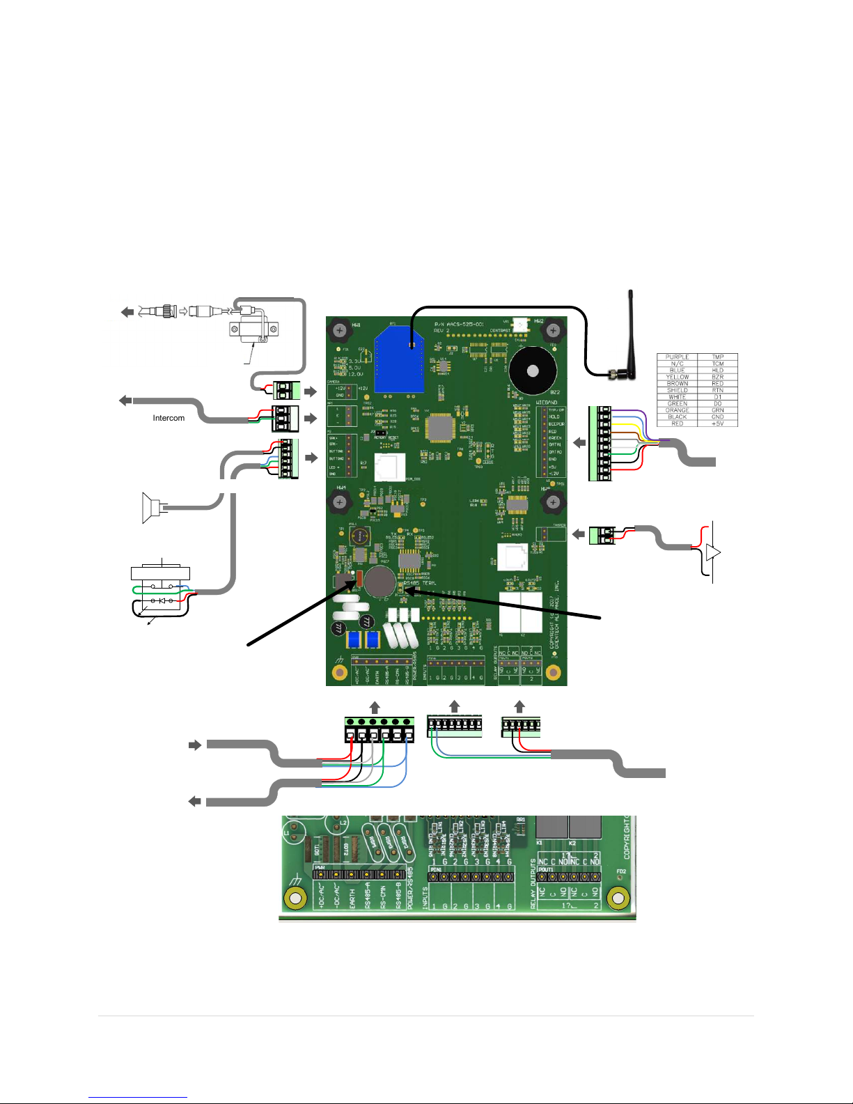
PWR/RS485: Power and RS485 data communication is done with a single connector and should be the
last connector to be attached as it may carry active power. We recommend that power and RS485 data
communications be via a single 18 AWG, 4-conductor shielded cable. The shield drain wire can be used
as the EARTH common wire. Do not connect more than two (2) RS485 cables to one PCB. All PCBs shall
be connected as an inline chain beginning with the controller and ending with the last device. The last
device shall have a “termination” jumper installed as shown in Figure 10. It is located next to the tall
capacitor as marked. All other devices shall have this jumper omitted.
These connectors have 6 pins.
DC + V (12-24VDC) ……… Required.. RED
DC – V (DC Common) …… Required.. BLK
EARTH ……………………... Recommended.. SHEILD
RS485-A ……………………. Required..
RS-CMN …………………… Optional if EARTH is connected,
RS-485-B …………………… Required
RS485 Limitations: A wired keypad can be located up to 4000 feet from the controller given proper
twisted pair cable with ground wire is used.
To properly terminate cables into connectors the following instructions apply.
1. Strip back the outer insulation and shield foil from both of the 18 AWG, 4-conductor, shielded cables
(coming from the controller or previous AI device in line and going out to the next AI device in line),
being careful not to cut the bare shield wire. Strip ¼ inch of insulation off the end of each of the
individual colored conductor wires.
2. Remove the terminal blocks from the keypad circuit board by sliding them up and off. The terminal
blocks may be somewhat difficult to remove as a tight electrical connection is necessary. If they are
tight, rock them slightly back and forth while lifting away from the board.
3. Insert wires into the desired connector. Where 2 wires are tied together ensure that both wires are
seated all the way inside the slot. Use a flathead precision screwdriver to tighten down the terminal
screw.
4. Verify that the terminal slot has tightened down on the copper wire and not on the rubber insulation.
There should be no copper wire showing outside of the terminal slot. Gently tug the wires to verify that
they are tightly held inside the terminal slot. Repeat this process with each of the remaining wire
connections as shown in Figure 10.
Wireless Communications (Optional): Wireless Communications (Optional): The Keypad can also
function without the RS485 wiring. In this case the XBEE or XBEE Pro 900 MHZ wireless module and an
RPSMA antenna must be installed on the system Gateway and on the Keypad to operate wirelessly. If the
keypad or relay unit is within wireless range of the Gateway the keypad will work in same fashion as with
RS485 connections. The range depends on the wireless module used, the antenna used, the RF
background level of the area (rural or urban) and the number of obstructions between devices. The XBEE
basic module range is up to 300ft unobstructed line of sight rural area. Typical obstructed range of XBEE
in urban areas is 100 ft. The XBEE Pro module range is up to 1 mile w/unobstructed rural line of sight.
500ft obstructed line of sight in urban areas is common for XBEE Pro. XBEE Pro transmitter modules are
recommended. This equipment option has been tested and found to comply with the limits for a Class B
digital device, pursuant to Part 15 of the FCC Rules.
This option has not been evaluated nor certified as part of UL294 level 2 nor CSA C22.2 No.205

CIA-575-001 Rev 1.0
8 | P a g e
Relay Outputs: Each relay has a Normally Closed (NC), a Common and a Normally Open (NO) connection.
Depending on the need, wire to the common and either the NC or NO. On board LED’s are provided to
show if the relay is activated. Typical gate operators require a normally open contact. Some electric door
strikes require a normally closed contact. If door strikes are used it is recommended that they be DC
(typically 12V) so that a shunting diode must then be installed across the solenoid to prevent ground spikes
from disrupting the keypad communication.
RELAY CONTACT RATINGS:
Item
Rating
Contact Type Single Ag-Alloy (Cd Free)
Rated Load 5A (NO) / 3A (NC) @ 30VDC
Max Switching Voltage 30VDC
Max Switching Current
5A (NO) / 3A (NC)
Inputs: Each Input has a Ground Connection (G) and a Sense Connection (1) . The sense connections are
marked 1-4 and will source a small voltage at high impedance. Wire any dry contact across a sense pin
and a G pin. Closing the contact will energize the input. On board LED’s are provided to show if the input
is activated.
Speaker and Call Button: These cables are factory installed but are shown in the figure above for
reference.
Intercom: The PCB provides a simple way to attach the intercom cable to the speaker and the call button.
Typically 2 wires are only present although a 3rd can be present. With two wires the interface supports both
Aiphone LEF and NEM systems. The 3rd wire (green), if present, is to be wired to the E connection along
with the black wire.
Earth Ground: The earth ground wire should be. To connect the ground wire, run an insulated copper wire
(preferably color green) from a grounded water pipe or from a copper rod in the ground to the keypad and
connect it to the green earth ground wire using a wire nut. The enclosures earth wire is connected to the
stud in the floor of the enclosure using a screw with a star washer. This installation must meet applicable
code as the type of wire, depth of burial, and size of the rod may vary by municipality. Note: Uninsulated
wires (Typically used for earth ground) cannot be located inside the unit’s case. Make connections for an
uninsulated ground wire outside the enclosure.
Pinhole camera Option. Video signal cable is part of the accessory device and not discussed herein. The
keypad does have accessory power (12V as well as 5V) that can power a pinhole camera. This will give
the best possible picture from the keypad camera. Pinhole camera power is supplied by the keypad circuit
board. Depending on which camera is used a custom mounting bracket may be required.

CIA-575-001 Rev 1.0
9 | P a g e
Testing / Troubleshooting the Keypad: Test the keypad by applying power to the PWR/RS485
connections. An “Offline” message will initially be displayed after power is applied. Once the controller
recognizes the device a standard welcome message will appear. There are also multiple LEDs as shown
below that should be active as described for troubleshooting purposes.
Main Fuse – 2A
Littelfuse Inc. 39512000440
Voltage Present LEDs
(all 3 must be lighted)
RS485 Active LEDs
(must be flashing)
Micro Controller Running
(must be oscillating)
WEIGAND LED
RELAY STATE LEDs
INPUT STATE LEDs
Figure 5
Check the 3 Power LEDs on the Keypad PCB. If all are dark, check / replace the PCB fuse. If any single
specific power LED such as the 3.3V or 5V LEDs are dark, replace the main PCB.

CIA-575-001 Rev 1.0
10 | P a g e
Accessing the Display PCB and Push Button Sub-assembly’s: The main PCB is mounted on hinged
standoffs. Loosening 4 thumb screws allows the PCB to be folded back in place to access the Display
PCB and the metal push button assembly.
Figure 6
The push button assembly is a single part held in place by 4 nuts in the 4 corners of the unit. Similarly the
display PCB is held to its holder/retainer with 4 Philips head screws. Both can be easily changed after
removing the ribbon cable that connects them to the Main PCB.
The Display PCB mounts to a plastic carrier that also acts to hold the display window in place. The carrier
can be removed with 4 screws to access the window and the window seal gasket.
The Speaker is held in place with a retainer with 4 nuts. Its face is rubberized and does not need an
additional seal.
A plastic cover is provided to allow a near field device such as an iBeacon to be added. While not
intended to integrate into the keypad functionally, the separate module can be powered by the Main PCB
using the power connections (+5V/+12V) available on the Wiegand connector.

CIA-575-001 Rev 1.0
11 | P a g e
KEYPAD MAINTENANCE
Cleaning the Housing and Touchpad
Monthly: Inspect and clean the housing and touchpad on a regular basis (monthly) . To clean spray
the unit with a mild soapy water solution then wipe it with a soft cloth. Do not use alcohol, harsh
chemicals, abrasives, or petroleum-based products. Do not immerse the device in water or use a
pressure washer.
Yearly: Open the keypad, inspect and clean the inside of the unit. Remove dirt or dust that has collected
on the inside of the housing and the circuit board that could cause problems. Note any signs of water
damage or corrosion caused by a leak in the enclosure seals. Replace any worn seals. A small can of
compressed air can be used to remove insects and dust from the circuit board.
NOTICES and DISCLAIMERS
Liability Disclaimer: While every effort has been made to ensure the accuracy of the information in this document,
and we assume no liability for any inaccuracies contained herein. We reserve the right to change the information
contained herein at any time and without notice.
FCC Part 15 Notice: This equipment has been tested and found to comply with the limits for a Class B digital device,
pursuant to Part 15 of the FCC Rules. These limits are designed to provide reasonable protection against harmful
interference in a residential installation. This equipment can generate and radiate radio frequency energy and, if not
installed and used in accordance with the instructions, may cause harmful interference to radio communications.
Table of contents
Popular Keypad manuals by other brands

Chamberlain
Chamberlain LiftMaster Q installation manual

Digital Monitoring Products
Digital Monitoring Products 9800 SERIES installation guide

Insignia
Insignia NS-PNK8A01 Quick setup guide

Genie
Genie Series II installation instructions

LEGRAND
LEGRAND On Q lyriQ Instruction

Mitsubishi
Mitsubishi A8GT-TK Series user manual