Feasycom FSC-SYR16-7DB User manual

Shenzhen Feasycom Co.,Ltd Page 1/11 www.feasycom.com
FSC-SYR16-7DB
Long-distance range ultra-high frequency
electronic label reader
Instruction manual
Shenzhen Feasycom Co., LTD

Shenzhen Feasycom Co.,Ltd Page 2/11 www.feasycom.com
Catalogue
一、Introduction ..........................................................................................................................................................3
1、Technical Parameters ....................................................................................................................................... 3
2、Read-write size structure ................................................................................................................................. 4
3、Read-write use ................................................................................................................................................. 4
4、Main function of read-write .............................................................................................................................4
二、The read-write mode of operation and wiring instructions .................................................................................6
1、Read-write wiring instructions ........................................................................................................................ 6
2、Label operation .............................................................................................................................................. 6
3、The way of work ..............................................................................................................................................7
4、ID neighbor discrimination ..............................................................................................................................7
三、Read-write configuration ....................................................................................................................................... 7
四、Read-write installation ...........................................................................................................................................8
1、Read-write installation .....................................................................................................................................8
2、Read-write fixed and height adjustment ........................................................................................................9
3、Read-write azimuth adjustment .....................................................................................................................9
4、Installation examples - vehicle parking lot management ..............................................................................10
Shenzhen Feasycom Co., LTD

Shenzhen Feasycom Co.,Ltd Page 3/11 www.feasycom.com
I、Introduction
1. The product has multi-protocol compatibility, fast reading rate, waterproof appearance design, to
meet the requirements of harsh working environment.
2. Fully support ISO-18000-6C (EPC G2) electronic tags;
3. Support USB, RS232 and Wiegand26/34 and other communication methods;
4. Output power up to 30dbm adjustable, support timing mode, master-slave mode, trigger mode and
other modes of operation;
5. Application suitable for: vehicle access control, non-stop automatic toll collection, personnel
access control management, logistics monitoring, production automation management and other
fields.
1、Technical Parameters
Operating
frequency
Standard configuration ISM 902~928MHz or ISM 865~868MHz optional, other bands
can be customized.
Antenna Gain
Built-in circularly polarized antenna with 7dBi gain
Pact
ISO18000-6C(EPC G2)
Development kit
Provide SDK development kit, and provide C#, VC, VB, Java, Delphi development
routines
Hardware
Provide test DEMO and automatic card writing, card reading DEMO, convenient for
customers to issue and write cards
Output power
0~30dBm,Software adjustable
Communications
interface
N-shape:Wiegand26/34, RS232/RS485, USB
E-shape:Wiegand26/34, RS232/RS485, TCP, USB
Input interface
1 Trigger Input
Reading method
Timed automatic card reading and externally triggered controlled card reading, set by
software
Reading speed
Less than 6ms per 64bits average read time for a single card, set by software
Reading distance
0-5 m (0~8 m for high power) (The reading distance is related to the tag and the field
environment)
Operating
temperature
-40℃~+65℃
Storage
temperature
-45℃~+95℃
Shenzhen Feasycom Co., LTD

Shenzhen Feasycom Co.,Ltd Page 4/11 www.feasycom.com
Power
Requirements
DC12V,3A
Dimension
215mm×215mm×50mm
Weight
0.8 Kg (1.8kg with packaging)
2、Dimensional structure of the reader
unit (of measure):mm
3、Read/Write Usage
It can be used for item identification and data collection, and can be widely used in the following
fields in particular, taking advantage of the good characteristics it possesses:
1) Transport management: road and railway transport management and container transport
management, etc;
2) Motor vehicle management: monitoring and management of various motor vehicles by public
security, traffic and other departments;
3) Road and bridge tolls: due to the product has a long-distance high-speed reading tag data, road
Shenzhen Feasycom Co., LTD

Shenzhen Feasycom Co.,Ltd Page 5/11 www.feasycom.com
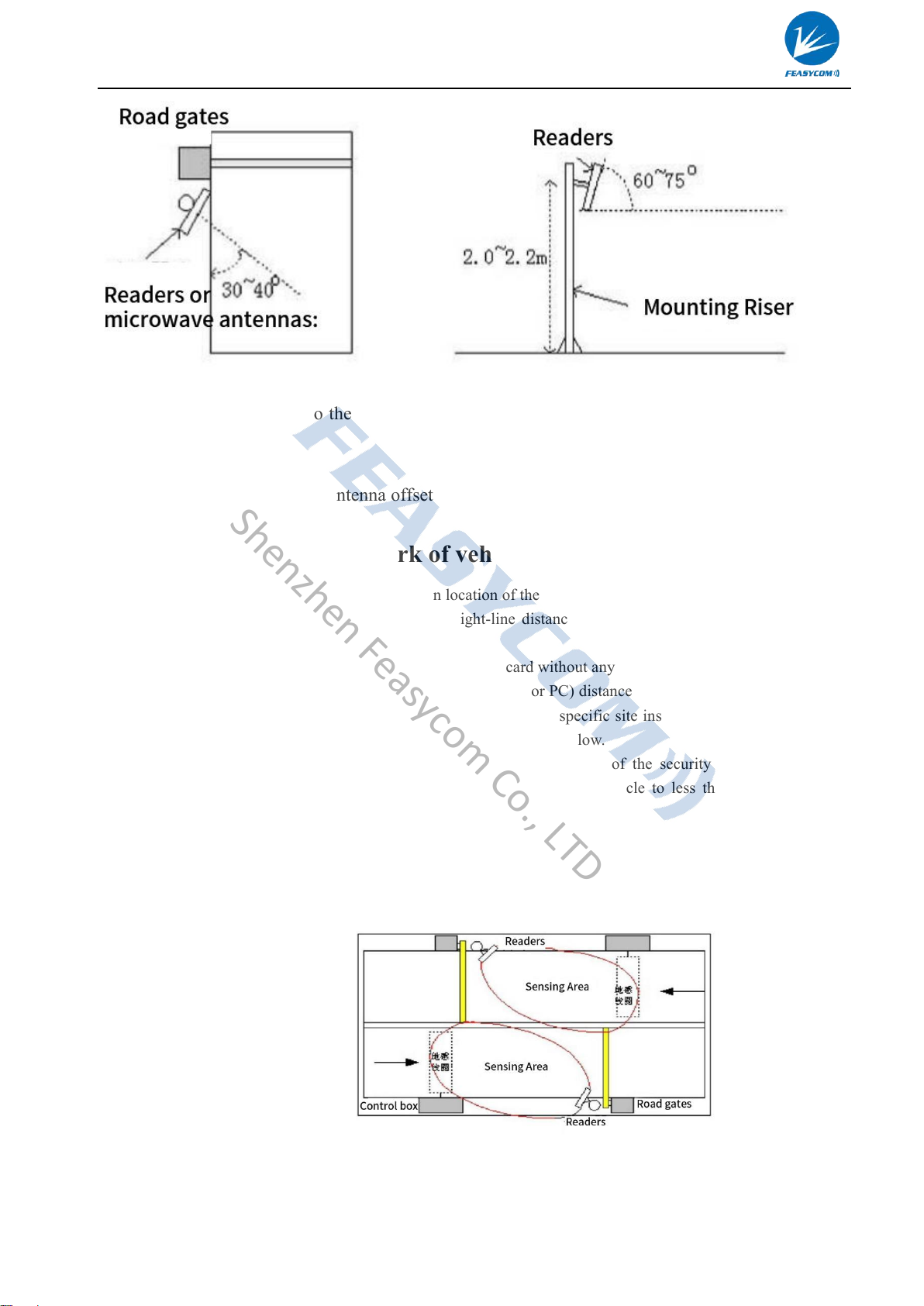
and bridge tolls can be carried out without stopping;
4) Customs clearance management: customs clearance, customs transfer of materials and vehicle
management;
5) Warehousing logistics management: commodity flow and warehousing management as well as
mail, parcels, aviation baggage and other flow management;
6) Car park management: automation of management and charging;
7) Access control management: including vehicle and personnel access management;
8) Process production flow: monitoring parts in the whole production process;
4、Main functions of the reader
1) Wake up the tag: only the tag can be awakened to communicate with the reader, to prevent the interference
of other tags outside the system, to ensure that the reader and the system tag information exchange is
reliable and accurate.
2) read tag data: not only can read the ID number of the tag, but also read the data in the specified tag storage
area; not only can read a single tag data, but also can read multiple tags within the antenna wave range at
the same time.
3) Write tag data: can write data to the specified tag storage area.
4)It can be directly connected to control devices with standard Wiegand26/34 interface without development
and easy to use.
5)Connect with controller or PC through standard communication interface for data communication and
exchange; SDK development kit is provided for users to further develop applications.
6)Precautions for use
a) R16 series read-write is generally connected with computer through RS232 data interface for data
exchange. Because R16 series read-write can only read and write to the electronic label after receiving
the control command from the controller, therefore, we will provide the SDK development package to
the customer, and the user can do the development of application software.
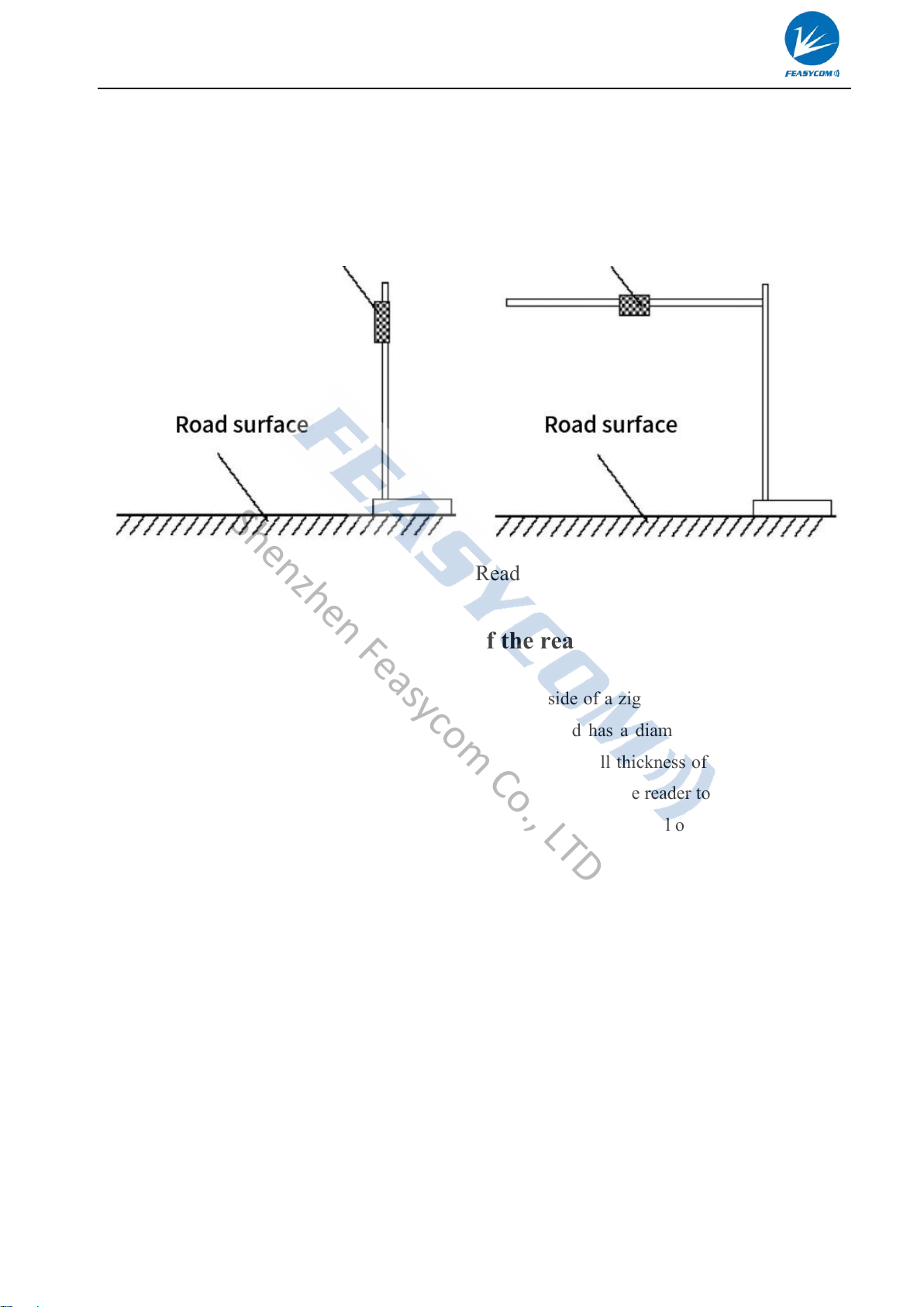
b) The read-write working temperature is: -40℃~+65℃. Therefore, when using this reader in cold areas
and seasons, it should be noted that the reader should be switched on and warmed up in advance 15
minutes before the reader is officially used to ensure the normal operation of the reader.
c) It is recommended that during the test, there should not be any objects blocking the reader within at least
Shenzhen Feasycom Co., LTD

Shenzhen Feasycom Co.,Ltd Page 6/11 www.feasycom.com
30 metres in front of the reader; when holding the card, please touch your fingers to the edges of the card
on both sides, and since this antenna is horizontally polarized, the card should be placed horizontally
right in front of the reader during the test to ensure the card reading effect.
d) Wigan communication interface must be connected to GND ground.
e)The installation height is above 1.8M, and the diameter of the vertical pole is 30-50CM.
7)Installation Diagram
2)
II、Read-write working mode and wiring description
1、Wiring instructions for the reader
2、Tag operation
Red
Black
Green
White
Grey
Purple
DC+(7-12V)
GND
RX
TX
WG-D1
WG-D0
Holding rod diameter 30-50mm
Shenzhen Feasycom Co., LTD

Shenzhen Feasycom Co.,Ltd Page 7/11 www.feasycom.com
EPC GEN2(ISO18000-6C)tag
Single Label Initialization: defines the EPC length of the label, usually 96 bits.
Single Tag Write: Write to the EPC of the tag, one address or multiple addresses can be written
at a time (based on 1 address).
Single Tag Lock: Lock the EPC of the tag. After locking, the EPC of the tag will not be
rewritten.
Single Tag Destruction: destroys the tag. After destruction, the tag will not be able to be used
again.
3、working method
1)COMMAND: In this mode of operation, the reader works under the control of a PC or other
controller. The reader and the controller can communicate with each other through one of the RS232,
RS485 or Ethernet interfaces. This mode of operation supports all the functions provided by the
secondary development kit.
2)TIMING READ: reader to a certain period (configurable) automatically read the card, read the
data through the specified communication port output. The operation of the label is read-only.
3)TRIGGER READ: When a low level is input to the trigger input port, the reader starts to read the
card periodically, and is automatically switched off after a period of time.
4、ID Neighbourhood Discrimination
ID Neighbourhood Discrimination is designed to reduce the redundancy of data uploaded by the
reader. When this function is selected, only one set of data will be uploaded within a set time when
the reader reads the same tag's card number several times in a row. Neighbourhood discrimination
can choose the effective time, that is, if the time interval between two adjacent readings exceeds the
effective time, they will not be adjacent than the judgement. Users should choose according to
specific needs. Commonly used in Wiegant communications.
III、Read/Write Configuration
Our company provides DEMO software programme for configuring the working parameters
of the reader/writer. The interface of the parameter configuration picture is shown below:
Shenzhen Feasycom Co., LTD

Shenzhen Feasycom Co.,Ltd Page 8/11 www.feasycom.com
For DEMO software use, please refer to the UHF Setup Software Manual.
IV、Installation of the reader
1、Installation of the reader
Mounting Clip Codes
brackets
Back of the reader
Shenzhen Feasycom Co., LTD

Shenzhen Feasycom Co.,Ltd Page 9/11 www.feasycom.com
Read-write stand mounting mode has two kinds: "Side 1 type installation" and "L stand mounting"
see the following figure: you can choose the installation mode according to the application
requirements and the actual site, in general the side mounting read-write distance nearer, but the
installation is simple; top mounting read-write distance is farther, but the installation is complicated.
Side 1 mounting of the reader Reader L stand type mounting
2、Fixation and height adjustment of the reader
When mounting the FSC-SYR16-7DB reader/writer on the side of a zigzag stand, it is required that
the mounting pole to which the reader/writer is to be mounted has a diameter of 30-50mm and a
length of 2.2m, and it is preferable to use stainless steel with a wall thickness of more than 1.2mm.
Use the fasteners provided in the FSC-SYR16-7DB reader box to fix the reader to the top of the pole.
Adjust the height from the centre of the FSC-SYR16-7DB reader to the level of the lane according to
the type of vehicle (mainly referring to large and small vehicles), which is usually about 2.0m (1.8 to
2.2m).
L-shaped stand top mounted, require the installation of L-shaped frame riser (or gantry-shaped)
diameter 60 ~ 80mm, crossbar diameter 30 ~ 50mm, it is best to use a wall thickness greater than 1.2
~ 2.0mm stainless steel materials. The FSC-SYR16-7DB reader is also fixed to the crossbar near the
middle of the carriageway using the fasteners supplied in the box. The height of the crossbar from
the ground should be adjusted between 3.5m and 4.0m depending on the height of the vehicle.
3、Reader azimuth adjustment
Shenzhen Feasycom Co., LTD

Shenzhen Feasycom Co.,Ltd Page 10 /11 www.feasycom.com
Antenna pitch angle: refers to the angle between the antenna tilted to the ground and the horizontal
line, about 60~75°.
Antenna azimuth: refers to the antenna offset angle to the direction of the lane, about 30~40°.
4、Installation example - park of vehicle car management
The principles for selecting the installation location of the FSC-SYR16-7DB reader system are:
1) FSC-SYR16-7DB read-write and the straight-line distance from the road gate should not exceed 1
metre
2) FSC-SYR16-7DB read-write location and the tag card without any items between the blockage
3) FSC-SYR16-7DB read-write and control equipment (or PC) distance as close as possible, and security
requirements for the use of shielded communication cables specific site installation and implementation
is generally based on site conditions to determine. Explained below.
a) Field installation mode 1: road without intermediate isolation of the security island, road control
equipment (road gates) installed on both sides of the road, the vehicle to less than 30 km / h speed
through the card reading area.
In this case: the requirements of the reader (antenna) should be close to the road gate equipment, while
the effective range of its reading tags (up to a straight line distance of 0.5 meters to 8 meters) can be
covered to the entrance and exit of the inlet and outlet of the ground sensing coils or the exit of the
ground sensing coils, the following picture shows.
b) Field installation mode
two: the road has
an intermediate isolation of the safety island, the control equipment (road gate) is installed in the
intermediate isolation of the safety island, the vehicle speed is less than 10 km / h through the card
Shenzhen Feasycom Co., LTD

Shenzhen Feasycom Co.,Ltd Page 11 /11 www.feasycom.com
reading area.
In this case: the requirements FSC-SYR16-7DB reader should be close to the road gate equipment, at the
same time so that the effective range of its read tag (the farthest straight line away from 0.5 m to 8 m) can
cover the entrance and exit of the inlet and outlet of the ground sensing coils or ground sensing coils, as
shown in the picture below.
Shenzhen Feasycom Co., LTD
Table of contents