FEB Series 765 Original operating manual

ES-F-765
SPECIFICATION SHEET
FEBCO product specifications in U.S. customary units and metric are approximate and are provided for reference only. For precise mea-
surements, please contact FEBCO. FEBCO reserves the right to change or modify product design, construction, specifications, or materials
without prior notice and without incurring any obligation to make such changes and modifications on FEBCO products previously or subse-
quently sold.
Job Name ––––––––––––––––––––––––––––––––––––––––––– Contractor
––––––––––––––––––––––––––––––––––––––––––––
Job Location ––––––––––––––––––––––––––––––––––––––––– Approval
–––––––––––––––––––––––––––––––––––––––––––––
Engineer –––––––––––––––––––––––––––––––––––––––––––– Contractor’s P.O. No. ––––––––––––––––––––––––––––––––––
Approval –––––––––––––––––––––––––––––––––––––––––––– Representative
––––––––––––––––––––––––––––––––––––––––
Series 765
Pressure Vacuum Breakers
Size: 1⁄2" - 2" (15mm - 50mm)
The FEBCO Series 765 Pressure Vacuum Breakers are used to protect
against health hazard and non-health hazard backsiphonage conditions in
industrial plants, cooling towers laboratories, laundries, swimming pools
and lawn sprinkler systems.
Features
• All bronze body for durability. One check valve and an air opening port in
one assembly.
• Lightweight poppet seals air opening under minimum flow conditions.
• Simple service procedures. All internal parts serviceable in line from the
top of the unit.
• Designed for minimum head loss.
• Engineered plastic bonnet protect valve bodies from freeze damage.
• Optional union end ball valves for easy removal and ultimate
freeze protection.
• End Connections – NPT ANSI/ASME B1.20.1
Operation
The FEBCO 765 PVB is designed to be installed to provide protection
against backsiphonage of toxic or non-toxic liquids. It consists of a spring
loaded check valve which closes tightly when the pressure in the assembly
drops below 1psi or when zero flow occurs, plus, an air relief valve that
opens to break a siphon when the pressure in the assembly drops to 1psi.
Specifications
Pressure Vacuum Breaker assemblies shall be installed to withstand
pressure for long periods and to prevent backflow of contaminated water
into the potable water system in backsiphonage conditions. The Pressure
Vacuum Breaker assembly shall consist of a single spring loaded check
valve which closes tightly when water flow through the assembly drops
to zero, and a single air relief valve that opens to break the siphon when
pressure drops to 1psi. The assembly shall include two resilient seated
shut-offs and two resilient seated test cocks, considered integral to the
assembly. Assemblies must be factory backflow tested. The check valve
and air inlet valve must be constructed to allow in-line servicing of the
assembly. The valve body shall be constructed of bronze. The check, pop-
pet and bonnet assembly shall be constructed of engineered plastic to
protect the valve body from freeze damage.
Pressure Vacuum Breaker assemblies shall be installed a minimum of
12" (300mm) above the highest downstream outlet, and the highest point
in the downstream piping. The assembly shall be rated to 150psi working
pressure and water temperature from 32°F to 140°F. The assembly shall
meet the specifications of the USC - FCCC & HR Manual.
Pressure Vacuum Breaker assemblies shall be FEBCO Series 765 or prior
approved equal.
Approvals – Standards
• Approved by the Foundation for Cross-Connection Control and Hydraulic
Research at the University of Southern California.
Applications
PVB assemblies are used to protect against health hazard and non-health
hazard backsiphonage conditions in industrial plants, cooling towers labora-
tories, laundries, swimming pools and lawn sprinkler systems.
Typical Installation
Pressure Vacuum Breaker assemblies should be installed at least
12" (300mm) above the highest piping and outlet downstream of the
assembly to preclude backpressure. Assemblies should be installed so
they are easily accessible for maintenance, periodic testing, and where dis-
charge will not be objectionable. They should be protected from freezing. If
the assemblies are subject to freezing temperatures, the freeze protection
procedures outlined in "Service Instruction Freeze Protection Model 765"
must be followed. Assemblies must not be installed where backpressure
could occur.
The discharge pressure shall be maintained above 3.0psi on
1⁄2" - 11⁄4" (15 - 32mm) sizes and 5.0psi on 11⁄2"- 2" (40 - 50mm) sizes to
insure seating of the spring loaded air inlet poppet.
Thermal water expansion and/or water hammer down stream of the back-
flow preventer can cause pressure increases. Excessive pressure should
be eliminated to avoid possible damage to the system and assembly.
765
12" (300mm) above the highest downstream
outlet and the highest point in
the downstream piping
Flow
1020 B64.1.2
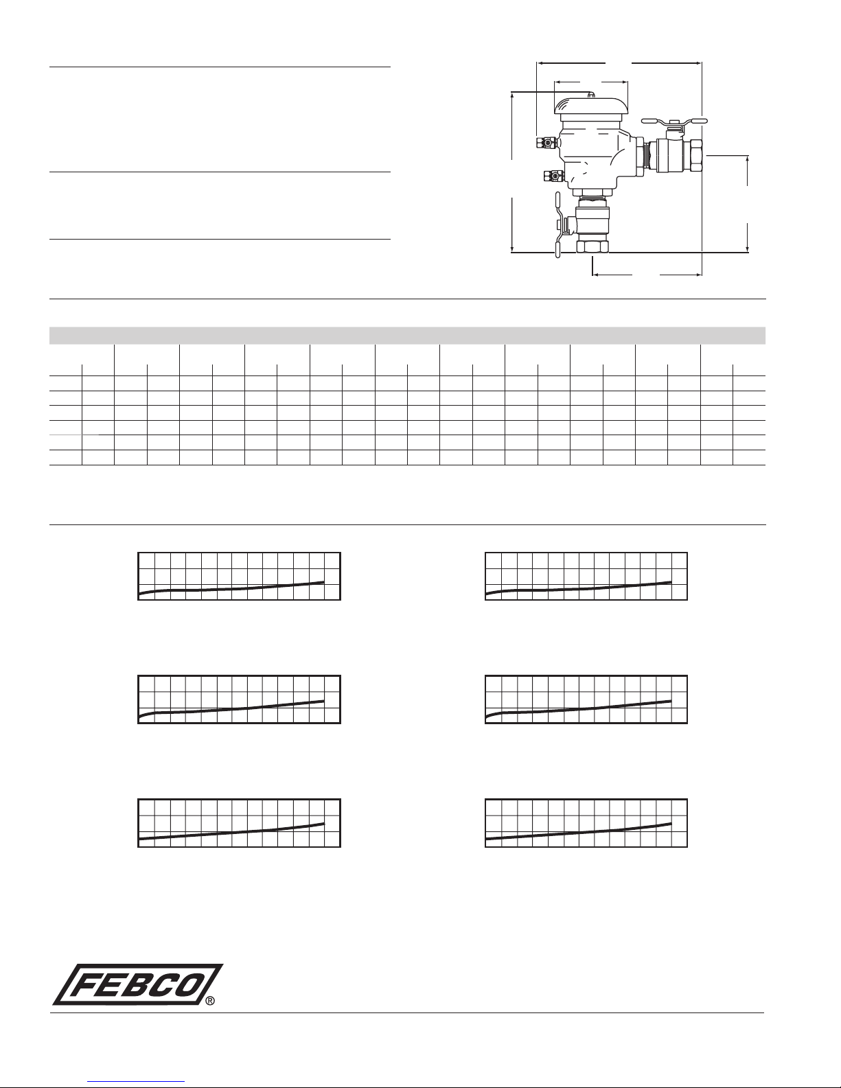
SIZE (DN) DIMENSIONS WEIGHT
A A1 (union) B B1 (union) C D D1 (union) E E1 (union)
in. mm in. mm in. mm in. mm in. mm in. mm in. mm in. mm in. mm in. mm lbs. kgs.
1⁄215 61⁄4159 7 178 63⁄4172 71⁄2197 21⁄264 33⁄495 41⁄211 4 4 1⁄4108 5 127 2.6 1.2
3⁄420 61⁄2165 73⁄8187 7 178 77⁄8200 21⁄264 4 102 47⁄8124 41⁄2114 5 3⁄8137 2.9 1.3
1258
3⁄4222 95⁄8245 9 229 915⁄16 252 4 102 51⁄4133 63⁄16 15761526
15⁄16 176 5.9 2.7
1
1⁄432 91⁄4235 101⁄4260 10 254 11 279 4 102 61⁄4159 71⁄4184 7 178 8 203 7.0 3.2
1
1⁄240 113⁄4299 127⁄8327 11
1⁄2292 125⁄8321 61⁄2165 71⁄4184 83⁄8213 73⁄4197 83⁄4225 14.8 6.7
25012
1⁄2318 133⁄4349 121⁄4311 131⁄2343 61⁄2165 8 203 91⁄4235 81⁄2216 93⁄4248 16.5 7.5
Note: Weights shown do not include union end ball valves and are approximate. Dimensions shown are nominal, allowance must be made for normal manufacturing tolerances.
Dimensions – Weights
Size: 1⁄2" - 2" (15 - 50mm)
Pressure – Temperature
Max. Working Pressure: 150psi (10.3 bar)
Hydrostatic Test Press: 300psi (20.7 bar)
Temperature Range: 32°F to 140°F (0°C to 60°C)
Materials
Main Valve Body: Bronze
Elastomers: Nitrile
Models
• Union End Ball Valves
• Bronze Bonnet, 1" & 11⁄4" (25 & 32mm)
A
B
C
E
D
B1
A1
E1
D1
Capacity
3⁄4" (20mm)
kPa psi
103 15
69 10
34 5
0 0
HEADLOSS
1⁄2" (15mm)
kPa psi
103 15
69 10
34 5
0 0
0 2 4 6 8 10 12 gpm
0 8 15 23 30 38 45 lpm
5 7.5 10 fps
1.5 2.3 3.1 mps
HEADLOSS
0 5 10 15 20 25 30 gpm
0 19 38 57 76 95 114 lpm
5 7.5 10 15 fps
1.5 2.3 3.1 4.6 mps
1" (25mm)
kPa psi
103 15
69 10
34 5
0 0
HEADLOSS
0 10 20 30 40 50 60 gpm
0 38 76 114 151 190 227 lpm
5 7.5 10 15 20 fps
1.5 2.3 3.1 4.6 6.1 mps
11⁄4" (32mm)
kPa psi
103 15
69 10
34 5
0 0
0 20 40 60 80 gpm
0 76 151 227 304 lpm
5 7.5 10 15 fps
1.5 2.3 3.1 4.6 mps
HEADLOSS
11⁄2" (40mm)
kPa psi
103 15
69 10
34 5
0 0
HEADLOSS
0 20 40 60 80 100 120 gpm
0 76 151 227 304 379 454 lpm
5 7.5 10 15 fps
1.5 2.3 3.1 4.6 mps
2" (50mm)
kPa psi
103 15
69 10
34 5
0 0
HEADLOSS
0 40 80 120 160 gpm
0 151 304 454 606 lpm
5 7.5 10 15 fps
1.5 2.3 3.1 4.6 mps
A Division of Watts Water Technologies, Inc. USA: 3816 S. Willow Ave. • Fresno, CA • 93725 • Tel. (559) 441-5300 • Fax: (559) 441-5301 • www.FEBCOonline.com
Canada: 5435 North Service Rd. • Burlington, ONT. • L7L 5H7 • Tel. (905) 332-4090 • Fax: (905) 332-7068 • www.FEBCOonline.ca
ES-F-765 0651 © FEBCO, 2006
Table of contents
Other FEB Power Tools manuals


