fec heliports equipment HP0832 User manual

Powered by eAGLe Light Engines ™ Interleader Limited
Remote Lighting Controller
FEC Type: HP0832
User Manual –Specification –Diagnostics
RLC Version 4 Issue: 1 26th August 2020
Note that this manual relates to
System V4.0 and Software V4.00 onwards

FEC Remote Lighting Controller V4 HP0832
User Installation and Operation Manual
© Interleader Ltd 2020 2 of 64 26/08/2020
Table of Contents
1Compliance Statement - USA.............................................................................5
2Compliance Statement –Europe........................................................................6
3Overview.............................................................................................................7
3.1 Key Features ......................................................................................................7
3.2 Part Numbers......................................................................................................7
4Architecture of Remote Lighting Controller.........................................................8
5Principles of Operation........................................................................................9
5.1 Keypad and LCD Display - Overview..................................................................9
5.2 Systems Management Software –Overview....................................................10
5.3 User Types .......................................................................................................11
5.4 Modes of Operation ..........................................................................................11
5.5 Channels...........................................................................................................11
5.6 Activation Options.............................................................................................12
6Setup through the Keypad and LCD Screen.....................................................13
6.1 Entering Menu Mode.........................................................................................14
6.2 Setup Control Unit.............................................................................................15
6.2.1 Radio 15
6.2.2 Cellular Radio 19
6.3 Input and Output Testing Menu ........................................................................20
6.3.1 Test Relays 20
6.3.2 BMS Input and Output Tests 21
6.4 Setup Systems..................................................................................................22
6.4.1 Set Channel Timeouts 22
6.4.2 Set Real Time Clocks 23
6.4.3 Reset and Reload (Software) 24
7Operation..........................................................................................................25
7.1 Activated via Start-Up.......................................................................................25
7.2 Activated by Input .............................................................................................26
7.3 Activated by keypad..........................................................................................26
7.4 Activated by VHF..............................................................................................27
7.5 Activated by SMS..............................................................................................27
8System Management Software (SMS)..............................................................28
8.1 Preparing for Installation...................................................................................28
8.2 Materials on the Supplied Media (USB or CD)..................................................28
8.3 Installing Systems Management Software (SMS).............................................28
8.4 Selecting the Communication Channel and Device..........................................30
8.5 Product Menu ...................................................................................................31
8.6 Security.............................................................................................................32
8.7 Unit Build Commands.......................................................................................33
8.8 Program............................................................................................................36
8.9 Unit History and Status.....................................................................................38
8.10 Reset & Restore ...............................................................................................39
8.11 Test...................................................................................................................40
8.12 Control..............................................................................................................41
9Installation.........................................................................................................42
9.1 Locating the Controller......................................................................................42
9.2 Things you will need .........................................................................................42
9.3 Preparing for Installation...................................................................................42

FEC Remote Lighting Controller V4 HP0832
User Installation and Operation Manual
© Interleader Ltd 2020 3 of 64 26/08/2020
9.4 Installing the Base Unit.....................................................................................43
9.5 Installing the Cell aerial.....................................................................................43
9.6 Electrical Installation.........................................................................................44
9.7 Circuit Connectors and Cable Entry (V4 enclosure) .........................................44
9.8 Relays...............................................................................................................44
9.9 Mains wiring......................................................................................................45
9.10 Basic Wiring Diagram .......................................................................................46
9.11 Basic Circuit Testing.........................................................................................47
9.11.112V DC PSU 47
9.11.2Manually checking the mains switched circuit 47
9.12 Final Assembly .................................................................................................47
10 Summary Specification.....................................................................................48
11 Cellular Radio...................................................................................................49
12 Power Supply Unit Specification.......................................................................50
13 Spare Parts.......................................................................................................50
13.1 Relays...............................................................................................................50
13.2 Other.................................................................................................................50
14 Factory Default Settings....................................................................................51
15 Diagnostics and Fault Finding...........................................................................52
16 Appendix 1 –Software Updater........................................................................53
17 Appendix 2 –Aux Input and BMS Input/Output and MetPak Interface..............55
17.1 Auxiliary Cable Harness - HP0827....................................................................56
17.2 Example Switch –Twilight Switch.....................................................................57
18 Appendix 3 –Aerials and Cables......................................................................58
18.1 Mains Cables, Switches and Fuses..................................................................58
18.2 Cell Aerial .........................................................................................................58
18.3 VHF Aerial ........................................................................................................58
19 Appendix 4 –Bluetooth Radio –EU Declaration of Conformity........................61
20 Appendix 6 –Mounting Template .....................................................................63
FEC Remote Lighting Controller V4 HP0832
User Installation and Operation Manual
© Interleader Ltd 2020 4 of 64 26/08/2020
Document Revision Sheet
Version
- Issue
Date
Changes
4 - 1
26th June 2020
New Document for RLC V4 Production model
Notes
1) this manual covers all commands available to the Manager and User. Additional
commands available to FEC, System and the OEM are contained in separate
documents.
2) Optionally, the RLC contains a Cellular Radio. Throughout this document this is refered
to as the ‘Cell’.
Optional Meteorological Pack
(Pole Mounted)

FEC Remote Lighting Controller V4 HP0832
User Installation and Operation Manual
© Interleader Ltd 2020 5 of 64 26/08/2020
1 Compliance Statement - USA
FCC Compliance WARNING
Changes or modifications to the transmitter not expressly approved by the manufacturer could
void the user's authority to operate this RF device.
FCC Compliance Statement
This device complies with Part 15 of the FCC Rules. Operation is subject to the following two
conditions:
1. This device may not cause interference, and
2. This device must accept any interference, including interference that may cause undesired
operation of the device.
USA-Federal Communications Commission (FCC)
This equipment has been tested and found to comply with the limits for a Class B digital device,
pursuant to Part 15 of FCC Rules. These limits are designed to provide reasonable protection
against harmful interference in a residential installation. This equipment generates, uses, and can
radiate radio frequency energy. If not installed and used in accordance with the instructions, it may
cause harmful interference to radio communications. However, there is no ensured specification
that interference will not occur in a particular installation. If this equipment does cause harmful
interference to radio or television reception, which can be determined by tuning the equipment off
and on, the user is encouraged to try and correct the interference by one or more of the following
measures:
• Reorient or relocate the receiving antenna.
• Increase the distance between the equipment and the receiver.
• Connect the equipment to outlet on a circuit different from that to which the receiver is
connected.
• Consult the dealer or an experienced radio/TV technician for help.
Any changes or modifications not expressly approved by the party responsible for compliance
could void the user’s authority to operate the equipment.

FEC Remote Lighting Controller V4 HP0832
User Installation and Operation Manual
© Interleader Ltd 2020 6 of 64 26/08/2020
2 Compliance Statement –Europe
This product has been marked with the CE mark to show it is compliant with the relevant
standards.
FEC Remote Lighting Controller V4 HP0832
User Installation and Operation Manual
© Interleader Ltd 2020 7 of 64 26/08/2020
3 Overview
The Remote Lighting Controller (RLC) is a fully digital design that combines ease of installation
and use with sophisticated yet simple and secure configuration via the IP65 rated keypad and LCD
display or via SMS. This manual relates to the RLC Version 4.
3.1 Key Features
•Traditional VHF Pilot Controlled Lighting (PLC) configuration
•Simple 25kHz/8.33kHz frequency setting through front panel –no fiddly switches
•Defined number of presses to activate Channels 1, 2 or 3
•Programmable timeout for VHF, keypad and Cellular activation
•Each channel has fully independent time-out (10 seconds to 60 minutes)
•VHF and Cellular operation can be remotely enabled/disabled for extra security
•FCC/EU approved, Integrated Bluetooth module for local SMS control
•Optional FCC/EU approved universal Cellular Radio Module for remote SMS control
•Secure PIN code protected SMS commands to monitor and control your installation
•Secure status reporting –check out your installation before taking off
•Remotely activate Channels 1, 2 or 3
•3 Status relay contact outputs for BMS interface
•4 Auxiliary and 1 BMS input for switching or BMS control of VHF receiver
•Five 20 Amp heavy duty relays (3 Channels, Windsock & Beacon)
•Local and remote test and diagnostics integrated into the unit
•Very low power consumption –Approx. 3W (idle) and less than 30W max. (including
internal winter heater)
•Operates from 110-240V AC 50-60Hz or 12V DC (ideal for solar and batteries)
•Weather station interface for meteorological information from your helipad
3.2 Part Numbers
Standard Equipment
RLC V4 Base System
HP0832
Optional Extras
Meteorological Station
HP0659
Interface Harness
HP0827
Cellular Radio V2
HP0839
.
FEC and Interleader Ltd have a policy of continuous product improvement and reserve the
right to change specifications of products. See website for latest details.
FEC Remote Lighting Controller V4 HP0832
User Installation and Operation Manual
© Interleader Ltd 2020 8 of 64 26/08/2020
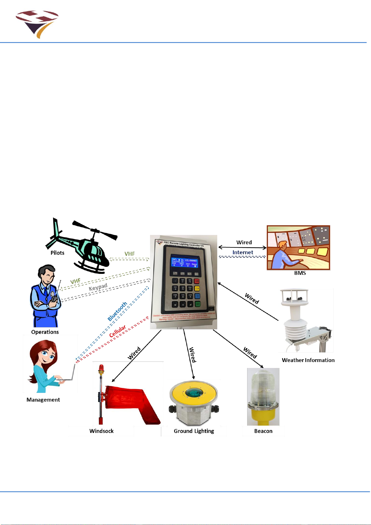
4 Architecture of Remote Lighting Controller
Effective operator or pilot control of Helipad Lighting is critical to the safe operation of an
installation. Traditional radio Pilot Controlled Lighting (PCL) solutions using the VHF radio is a tried
and trusted method.
Now there is a new way to control your lighting and peripheral circuits using FEC’s new RLC
which integrates both traditional VHF PCL and adds Systems Management Software (SMS)
control and monitoring with the option of automatic weather reporting (wind speed/direction,
temperature, dew point and pressure) right from your helipad.
FEC’s RLC sits at the heart of a monitoring and control capability bringing together for the first
time remote lighting control, helipad weather and system reporting.
The architecture can be used simply to control lights or, with additional meterological sensors, to
provide richer monitoring and reporting both by helipad operators and other agencies.
All of these features are under the full and secure control of the owner/operator and are the basic
building blocks on which future FEC developments will be built.
RLC V4 Architecture

FEC Remote Lighting Controller V4 HP0832
User Installation and Operation Manual
© Interleader Ltd 2020 9 of 64 26/08/2020
5 Principles of Operation
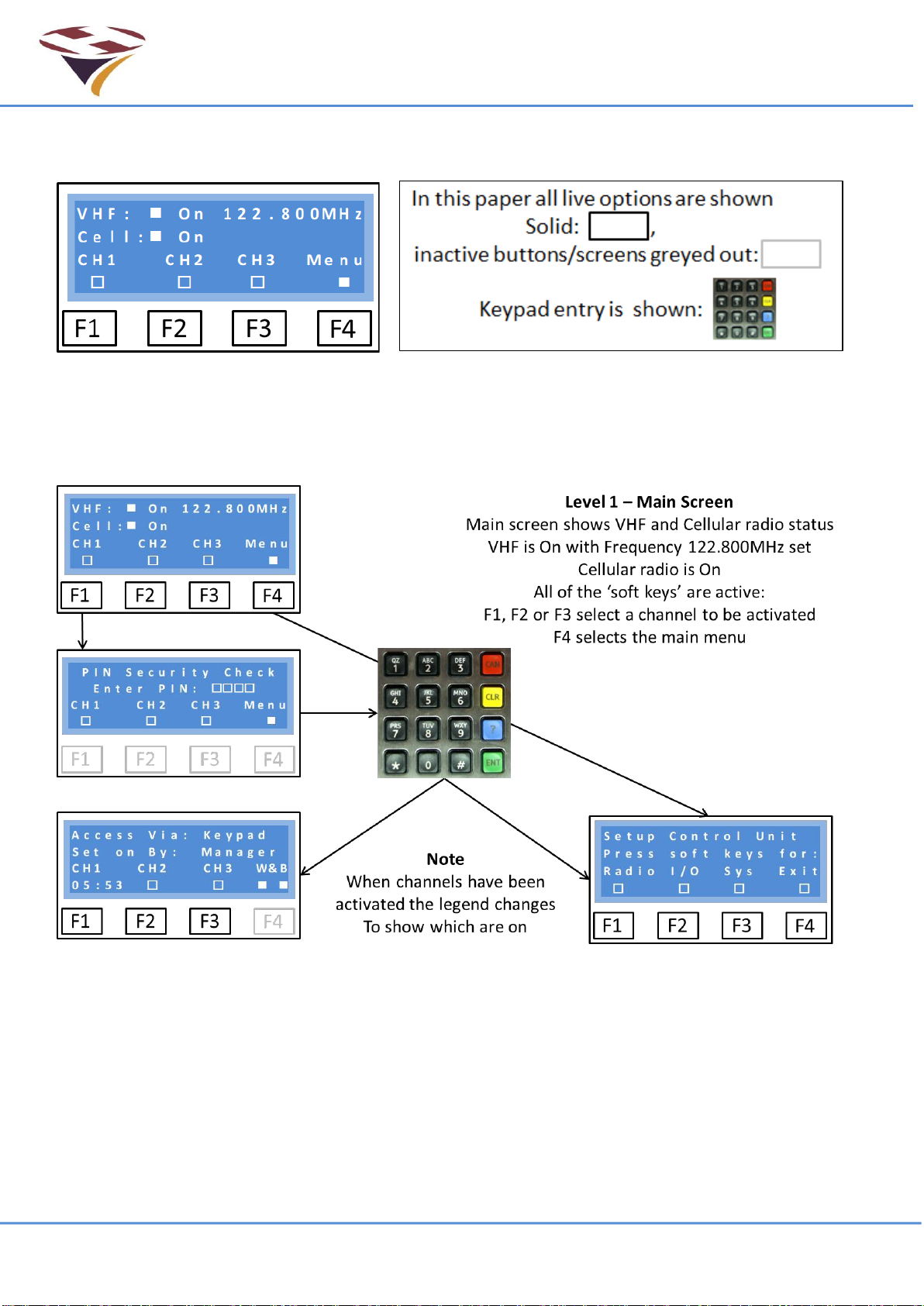
5.1 Keypad and LCD Display - Overview
The basic functions of the RLC are configurable via the front panel keypad and screen.
Basic setup, test and monitoring of the controller is carried out via the front panel keypad and LCD
display. There are no controls inside the case.
The menus are arranged in an hierarchical structure with a consistent presentation format and key
operation. Extensive use is made of the 4 ‘Function Keys’ above the main 16 key keypad and, in
conjunction with changing legends on the screen, intuitively guide the user through the various
steps. Key features of the interface are shown below.
In the example to the left:
The 1st line indicates VHF Radio on 122.800MHz.
The 2nd line indicates Cell Radio on.
The 3rd line confirms the function of each key.
The 4th line represents the Function Keys.
Note that in some menus the boxes in the 4th line also give the current status of that function. For
example, in the Test Output (O/P) test mode, the relays can be set and unset individually. As they
change state the squares change from open to solid to indicate the active state.
Note that in some menus more information is provided and hence the exact layout above not
followed. The approach is the same and where there are differences instructions provided.
F4, usually marked ‘Exit’, returns to the previous level in the menu and in many screens accepts
the conditions set in that menu. If Marked ‘Quit’ then that screen is discarded before return.
Repeatedly pressing F4 will bring you back to the main menu.
LCD Screen Common Layout
Line 1 indicates the menu level
Line 2 provides instruction
Line 3 Indicates the ‘Function Keys’ function
Line 4 identifies the keys and their status
Function Keys 1-4 (left to Right)
Data Entry Keypad
FEC Remote Lighting Controller V4 HP0832
User Installation and Operation Manual
© Interleader Ltd 2020 10 of 64 26/08/2020
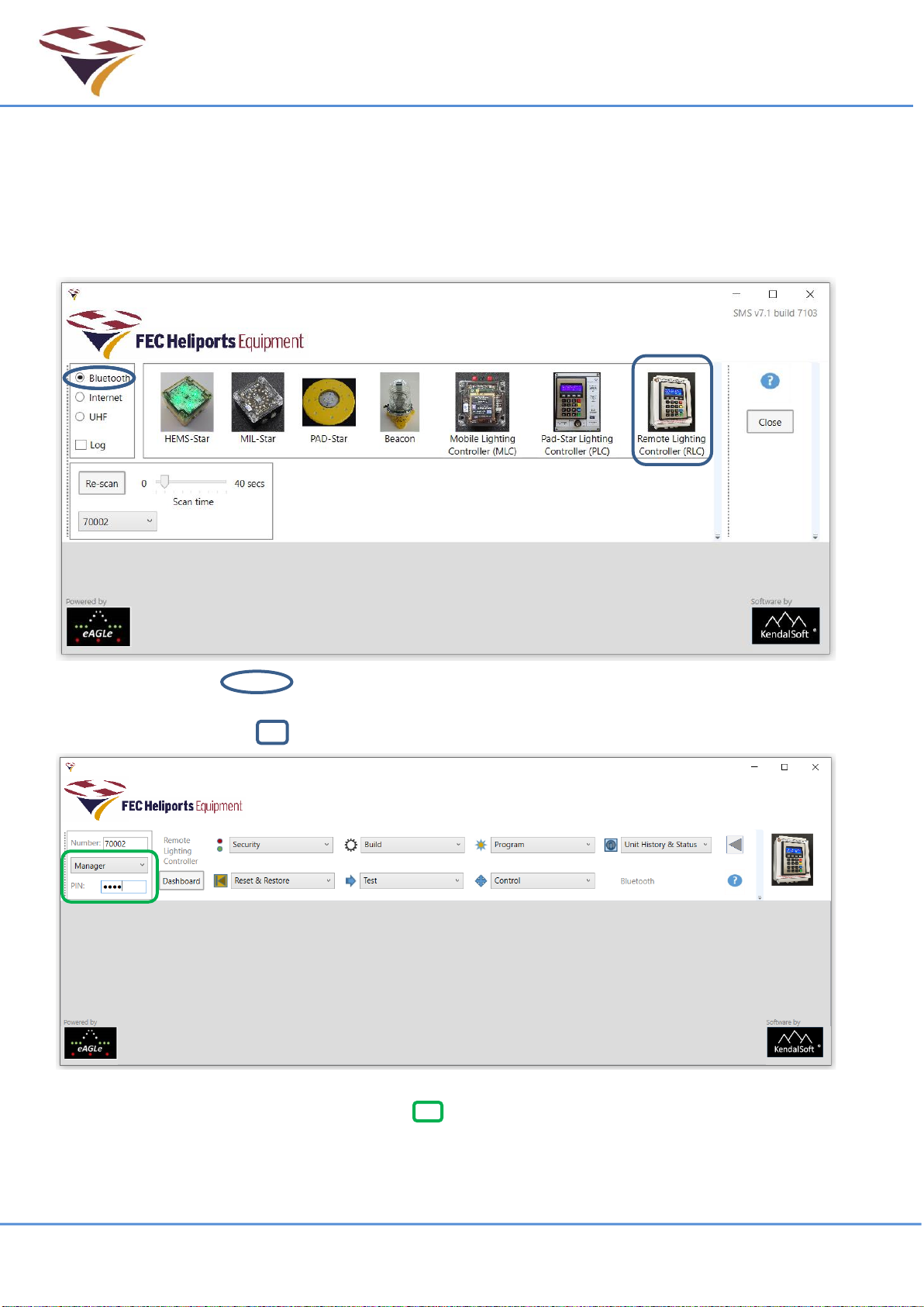
5.2 Systems Management Software –Overview
All FEC products can be configured, tested, controlled and monitored with the Systems
Management Software (SMS) via either a Bluetooth (included in all products) or Cellular Radio
Module (Optional extra) link.
SMS is run on any PC, Laptop or Tablet running MS Windows 10 and which supports Bluetooth
LE (V4.X). The main menu displays the products supported:
Select the link type (default is Bluetooth) and SMS will find all of the FEC products in
range and turned on. In this case it has found device serial number 70002 which is an RLC.
Click on the RLC image and SMS will connect to the desired device:
This is the main RLC Menu. To access the device through the menus, select your User Type
(example is Manager) and the relevant PIN . The Sub-menus are covered in later sections.

FEC Remote Lighting Controller V4 HP0832
User Installation and Operation Manual
© Interleader Ltd 2020 11 of 64 26/08/2020
5.3 User Types
Users of the system are classified by User Type. For security, each User Type has a unique PIN
code associated with it and different levels of access. User Types and their basic attributes are:
User –This is generally the pilot who has been given permission to use the system.
Manager –This is the owner or operator of the facility.
FEC –FEC have defined access to certain options (e.g. reset the Operators PIN).
System –Machine to Machine system interface for data logging
OEM –The Original Equipment Manufacturer has defined access to perform diagnostic and
support options.
Each type of user has a PIN access code and are arranged in an hierarchical manner –User has
the fewest privileges, OEM the most, to perform a variety of tasks on the system.
5.4 Modes of Operation
After the initial start-up sequence, when the system checks out its sub-systems, the RLC enters its
operational state continuously monitoring all of the triggers that can activate channels or provide
responses to either the Bluetooth or Cellular Radio Module interfaces.
The exception to this is when a user enters the menu mode from the keypad to perform setup or
testing operations. During this access all other inputs are ignored.
To avoid the RLC becoming ‘stuck’ in this state, after 10 minutes the RLC will return to its main
operational state. As an additional security measure, if PINs are not entered within 5 seconds of
each other, the screen times out and returns to the main menu. Also, if the wrong code is given
this is advised and a return made to the main programme.
Warning - Once the Menu Mode is selected, the system no longer monitors the VHF or Cell
receivers and will not respond to remote commands. All setups should be performed when it is
known that no movements requiring the lighting controller are required
5.5 Channels
The RLC uses the concept of ‘Channels’. Channels are activated via Start-Up, Inputs, the Keypad,
VHF or SMS. Channels are then mapped to control which relays are activated.
The default settings are as follows:
Keypad Action 1
VHF Action
SMS
Default Relay Activated
Function Key # 1 Pressed
3 ‘clicks’
Channel 1
Relay 1 activated
Function Key # 2 Pressed
5 ‘clicks’
Channel 2
Relay 2 activated
Function Key # 3 Pressed
7 ‘clicks’
Channel 3
Relay 3 activated
<CAN> Manager only
6 or 8 ‘clicks’
Channels Off
All relays de-activated
Notes:
1) 3, 5 & 7 clicks are the default but can be changed to any desired unique number per
channel
2) Any combination of relays can be activated instead of the defaults (see later section)
3) If Timeout Alert is active, The Winsock is flashed according to the parameters set through
SMS (default 10 minutes).
1
By default, no PIN is required to activate channels via the keypad. This can be changed via SMS

FEC Remote Lighting Controller V4 HP0832
User Installation and Operation Manual
© Interleader Ltd 2020 12 of 64 26/08/2020
5.6 Activation Options
There are five ways to activate channels:
•Start-up and Wired Inputs trigger channels to stay on until turned off, and
•Keypad, VHF and SMS all start timers to de-activate the channel after a defined period for
each channel.
1) Start-up The RLC can be configured so that at start-up (or after a power-cut) a specified
channel is activated.
The RLC remains in this state until another trigger. This is a ‘fail-safe’ option of operation.
Start-up channels are inactive by default and are configured via SMS.
2) Wired Inputs The RLC has 3 inputs (which can be activated by a switch or relay) which turn
on the channels with no time-out.
Wired Inputs have the highest priority of all triggers and once set cannot be cancelled
unless the switch/relay is opened.
3) Keypad All channels can be triggered by selecting Fn1 –Fn3 keys. The relevant channel will
be activated with the time-out timer running.
By default no PIN is required to activate channels via the keypad but this is configurable via
SMS.
4) VHF All channels can be activated by a pilot using a series of ‘Clicks’ - pressing the Push To
Talk (PTT) transmit switch in the aircraft. The relevant channel is activated with the time-out
timer running.
Each of the channels 1 -3 have a default number of clicks of 3, 5 & 7 respectively. The
number of clicks, including the option to cancel via VHF, are configured via SMS
5) SMS Channels can be controlled On (with timer running) or Off via SMS and either the
Bluetooth or Cellular Radio links.
As well as activating the 3 channels, both the Windsock and Beacon interfaces are activated by
default.
How channels control these, including a Windsock Alert is configurable via SMS.
Note that in this version of software channels are activated sequentially and only one channel can
be active at a time (although it can control up to 3 relays).
For example, if channel 1 is active and channel 3 is triggered, channel 1 will be immediately
cancelled and channel 3 activated.

FEC Remote Lighting Controller V4 HP0832
User Installation and Operation Manual
© Interleader Ltd 2020 13 of 64 26/08/2020
V H F :
n
O n 1 2 2 . 8 0 0
M
H z
C e l l :
n
O n
C H 1 C H 2 C H 3
M
e n u
n
6 Setup through the Keypad and LCD Screen
The top menu is not really a menu but rather the main status display page with two main options:
1) Select the menu, or
2) Directly activate a Channel.
If a cellular radio module is fitted the start-up
process includes checking, configuring and
connecting to the network. There are more
start-up screens showing this progress and it
takes 10 seconds. once the system has
performed its start-up checks the screen will
appear as shown right. A Cell Module is fitted,
the receiver is ON - shown by both the filled
box and the word ‘On’.
If a no cellular radio module is fitted the start-up
checks are skipped and the process is quicker.
The screen will appear as shown right. No Cell
Module is fitted
The screen provides the essential information to show the status of the system. Including:
Line 1: The VHF receiver is ON –shown by both the filled box and the word ‘On’ and the
operating frequency is shown –in this example a US UNICOM frequency.
Line 2: Cell Radio Module.
Line 3: Is the legend and functional description of the function keys
Line 4: Indicates the status of the channels. In this example, none are active (open boxes) and
the Menu is available via the Function Key 4 below it. The Menu box will flash
open/solid every second.
By default, the screen remains back-lit all of the time.
To save power (particularly useful in battery powered installations) the LCD screen back-light can
be set to ‘Auto’ in which case it goes out 30 seconds after the last key was pressed or the screen
was refreshed. To re-activate the backlight, simply momentarily touch any key and the screen will
light up for another 30 seconds.
During an Active Period (when the controller has been activated to turn on the lights) the screen is
regularly updated with a down-count to the end of the Active Period and so the screen remains on.
See section on SMS system setup.
V H F :
n
O n 1 2 2 . 8 0 0
M
H z
C e l l :
N o n e
C H 1 C H 2 C H 3
M
e n u
n
FEC Remote Lighting Controller V4 HP0832
User Installation and Operation Manual
© Interleader Ltd 2020 14 of 64 26/08/2020
6.1 Entering Menu Mode
To enter the Menu mode, simply press the function key (F4).
Note that the function key representation above is used consistently throughout the manual.
On pressing F4 (for the main menu) you will be taken immediately to the PIN challenge screen to
enter your security PIN. If successful, the Setup Control Unit menu will be displayed.
FEC Remote Lighting Controller V4 HP0832
User Installation and Operation Manual
© Interleader Ltd 2020 15 of 64 26/08/2020
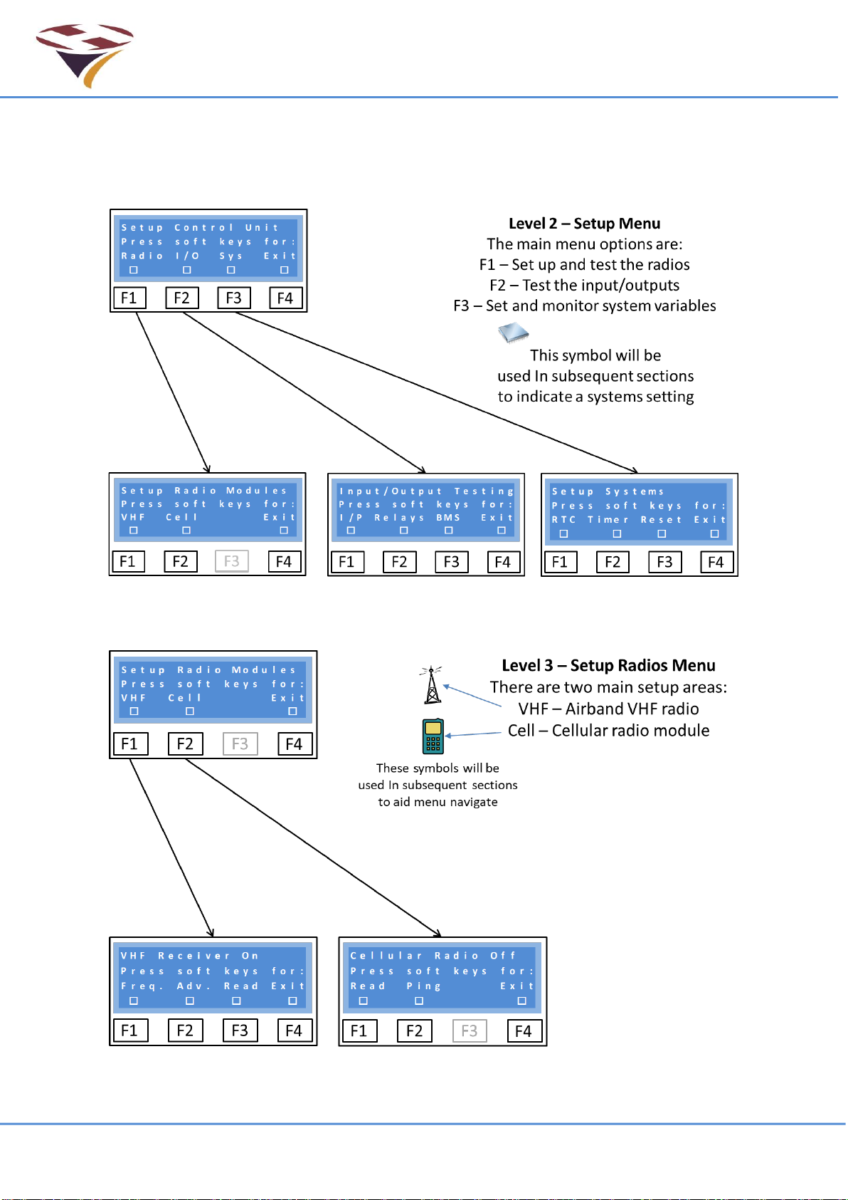
6.2 Setup Control Unit
The Setup Control Menu gives access to basic Radio, Input & Output and system settings. All of
these basic functions and many more sophisticated functions are also available via SMS which is
the advised method of system configuration and testing.
6.2.1 Radio
The Radio menu gives access to the VHF receiver and Cellular Radio module.

FEC Remote Lighting Controller V4 HP0832
User Installation and Operation Manual
© Interleader Ltd 2020 16 of 64 26/08/2020
6.2.1.1 VHF Receiver
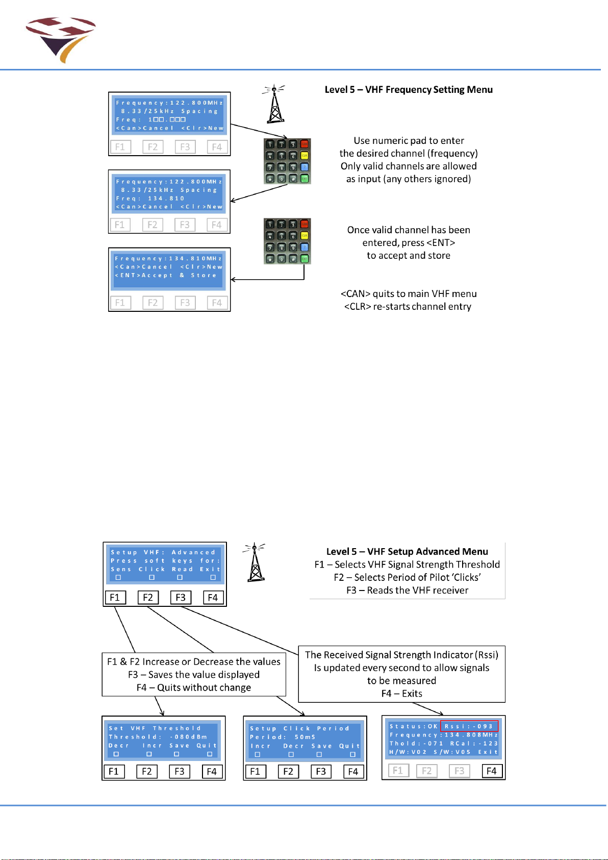
6.2.1.2 VHF Frequency Setting
The international channel convention of 8.33kHz provides 16 channels per 100kHz of bandwidth
and as a consequence not all frequencies are available. For example, 134.810 is valid but 134.815
is not.
Frequency reading
Note that in the screen (over the page) the frequency is displayed as 134.808MHz even though
the channel selected is 134.810. This is because the channels are a simplified and rounded (down
or up) representation of the frequency used.
A table showing the first 16 channels versus their frequency is shown below. The user does not
need to know any of this detail.
Channel
Frequency
Channel
Frequency
Channel
Frequency
Channel
Frequency
118.000
118.0000
118.025
118.0250
118.050
118.0500
118.075
118.0750
118.005
118.0000
118.030
118.0250
118.055
118.0500
118.080
118.0750
118.010
118.0083
118.035
118.0333
118.060
118.0583
118.085
118.0833
118.015
118.0166
118.040
118.0416
118.065
118.0666
118.090
118.0916
Note that the 25kHz spacing channels (italics) are an exact frequency but that the 8.33kHz
channels are not.
This pattern is repeated every 100kHz for all 3,040 channels.
FEC Remote Lighting Controller V4 HP0832
User Installation and Operation Manual
© Interleader Ltd 2020 17 of 64 26/08/2020
Frequency (Channel) Setting –as each number is entered it is checked to ensure that the
frequency (channel) is valid. If valid the number entered is displayed and the cursor moves to the
next space. Any invalid entries are ignored, nothing is displayed and the cursor does not move.
Once all numbers have been entered the system has ensured a correct and unique channel. The
full frequency is displayed (screen 3) and confirmation requested (<ENT>).
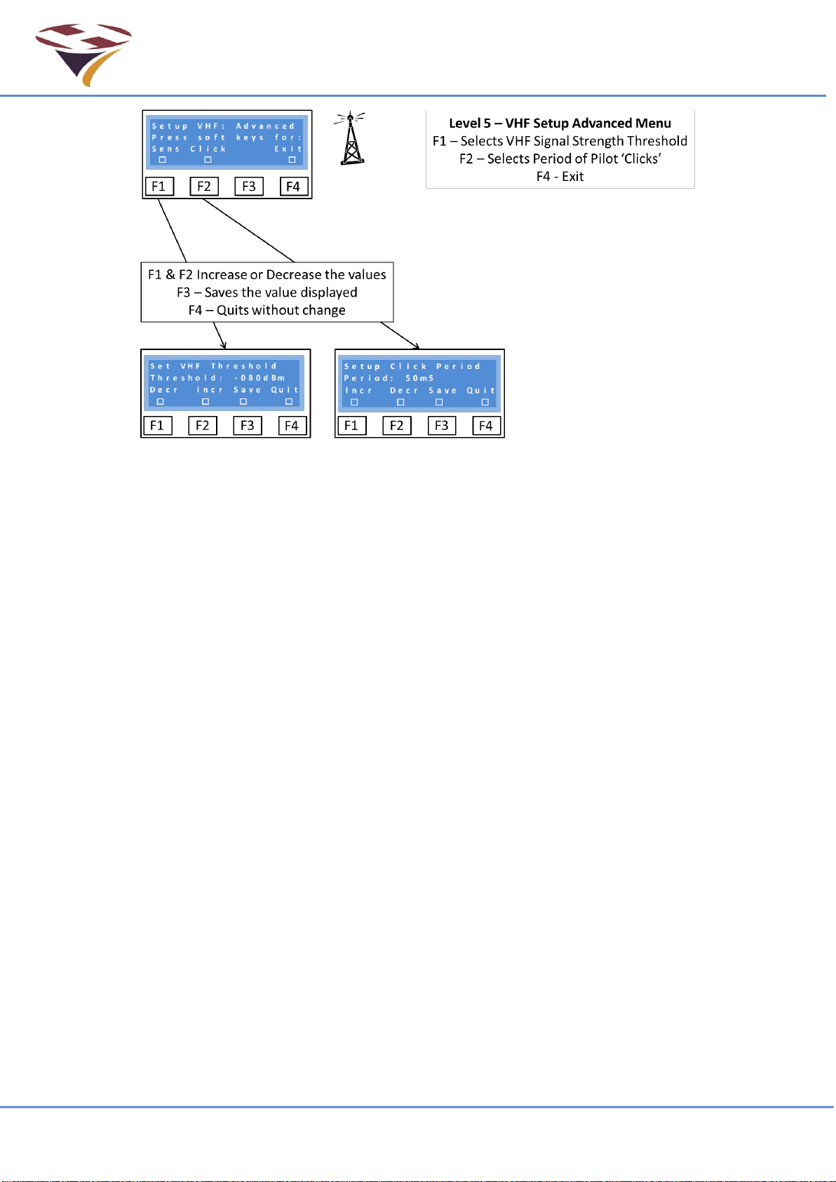
6.2.1.3 Setup VHF Receiver –Advanced
There are currently three menu options to:
1) Set the sensitivity of the VHF receiver threshold detection level (this is analogous to a
‘squelch’ on earlier systems)
2) Set the minimum period of the Pilot ‘Clicks’ (presses of the Push To Talk – PTT button),
which will trigger the system, and
3) Read the radio parameters in real time. This is an essential part of the setup process.
FEC Remote Lighting Controller V4 HP0832
User Installation and Operation Manual
© Interleader Ltd 2020 18 of 64 26/08/2020
Sensitivity –Setting the threshold
The Threshold is the level of Received Signal Strength at which the receiver is set to detect the
carrier signal (so called Carrier Detect) and is expressed as the power at the aerial socket.
By default it is set to -75dBm and can be varied between 0dBm and -125dBm (where 0dBm is the
highest level and -125dBm the lowest).
Great care should be exercised in setting the threshold too low (less than -80dBm) as noise may
cause false triggers. Equally if very high signal levels are experienced, an attenuator may need to
be introduced to the aerial feed.
Before changing the threshold level, read the section about the display of RSSI (Read command
below) as this will give good information about the local conditions.
Click –Setting the minimum PTT press period
As well as setting the signal level at which the system will trigger, the minimum length of time that
the Push To Talk (PTT) switch is activated can also be set.
This ‘Click’ period helps mitigate against the effects of ‘noisy’ switches which can otherwise cause
problems of false activations.
The system employs digital filtering of the received signal and waits for the signal to be stable
above the threshold level for the ‘Click’ time before it counts as a genuine PTT press.
Each click is counted in a 5 second period and if 3, 5 or 7 clicks successfully received, channels 1,
2 or 3 are set (see later section on mapping of channels to relays).
The default setting for Click is 100ms (100 milliseconds) and can be set between 1 and 250mS.
Some experimentation may be necessary to ensure correct operation in any particular installation.

FEC Remote Lighting Controller V4 HP0832
User Installation and Operation Manual
© Interleader Ltd 2020 19 of 64 26/08/2020
Reading the VHF receiver status
Selecting ‘Read’ retrieves and displays all of the relevant
status registers from the VHF receiver.
Of importance to the operator are:
1) That the status is OK
2) The Rssi level of the received signal
3) That the Frequency is as set and expected
4) That the Threshold level is as set and expected
Once this command is invoked, the receiver will be continuously re-read every 1 second and the
Rssi figure will be updated. This is extremely useful in checking the installation (aerials, down-feed
etc.) and setting up the receiver.
6.2.2 Cellular Radio
If a cellular module is fitted the basic module details, signal strength and quality can be obtained
and a network ‘ping’ to test the network connection are available.
These simple routines are useful in fault finding and diagnostics.
Read returns the basic information about the module and the network characteristics. In the
example above the module is attached to the UK O2 network with a reasonable signal strength
and low Bit Error Rate (BER) which is a measure of network quality.
Ping performs a network access ping to the service provider network. This test will take a few
seconds to complete.

FEC Remote Lighting Controller V4 HP0832
User Installation and Operation Manual
© Interleader Ltd 2020 20 of 64 26/08/2020
6.3 Input and Output Testing Menu
The 4 inputs, BMS input and 3 relays, 3 channel, Windsock and Beacon relays can all be tested
through the Input/Output Testing menu.
These tests are extremely useful during installation to check that all of the interface
In the lower left screen above input 1 has been made active and is shown in line 4 as ‘On’.
6.3.1 Test Relays
From the Test Relays Menu either the Channel relays or the Windsock and Beacon relays can be
tested.
6.3.1.1 Test Channel Relays
Pressing F1, F2 or F3 toggle the three relays 1 –3 respectively. As the relays are activated a
‘clunk’ should be heard from the unit. The coil currents of these relays are measured to ensure
there is continuity in the circuit. A figure of 100 +/-10mA should be displayed for the active relays.
When de-activated they can be heard disengaging.
This manual suits for next models
1
Table of contents
Popular Controllers manuals by other brands

Outback Power Systems
Outback Power Systems MX60 Installation, programming, and user's manual

MSTRONIC
MSTRONIC SOL10A12-56D-BT user manual

Pololu
Pololu Jrk G2 21v3 user guide

NZXT
NZXT SENTRY 3 user manual

JLCooper Electronics
JLCooper Electronics TransportPro RS422 user manual

DOA
DOA AH 15 Safety and maintenance manual


