4
MOVIDRIVE
®
Synchronous Operation DRS11A
1Introduction
1 Introduction
1.1 Description
The "synchronous operation" process permits a group of motors to be operated with synchronous
angular rotation or else with an adjustable proportional relation (electronic gear unit).
The master drive is the one which specifies the position. It can also be an incremental encoder. The
slave drive is the one which has to follow this position specification.
Synchronous operation is based on a constant comparison between the motor rotor angular posi-
tion of the master and that of the slave. The master and slave motors have to be equipped with
incremental encoders (DT/DV motors) or resolvers (DY motors) for this purpose. MOVIDRIVE®
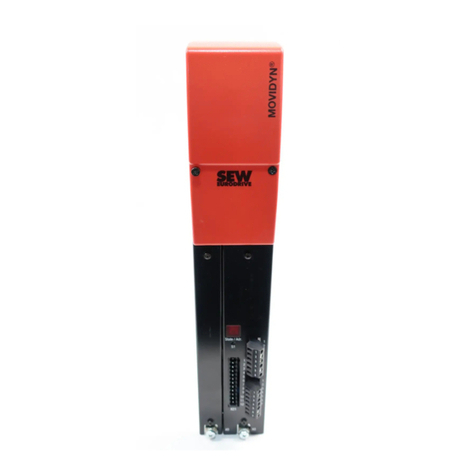
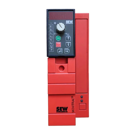
with the synchronous operation card type DRS11A is used as the slave drive. The DRS11A option
can only be used with MOVIDRIVE®
types MDV and MDS; it cannot be used with MOVIDRIVE®
type MDF (due to the lack of encoder or resolver feedback!).
The DRS11A option is plugged into the OPTION1 or OPTION2 slot in accordance with the pre-
scribed option combinations ( →MOVIDRIVE®
operating instructions).
For synchronous operation of master and slave, it is necessary to equip the slave inverter with a
braking resistor. Depending on the drive a braking resistor may also be required for the master
inverter during regenerative operation.
Using the P221 and P222 parameters (master and slave gear factor), the master and slave pulses
counted are converted for the output side of the gear. They are a measure of the pulses counted
per unit of travel distance.
The system determines the difference in the distance information between the master and the slave
and stores this value in the form of incremental encoder signals in an internal difference counter.
Binary indications such as "DRS SLAVE IN POS", "LAG ERROR", etc. are set depending on this dif-
ference.
This counter is evaluated differently for the different operating modes (P223).
•In synchronous operation (X40:1 = "0", for all 1 – 8 modes), the internal difference counter is
used for correcting to anglular deviation ∆α = 0.
• A "1" signal on X40:1 causes synchronous operation to be switched off and free-running opera-
tion to become effective. Free-running operation means that the slave no longer receives its set-
point from the master but that the setpoint source set in P100 is effective. Master and slave do
not run in angular synchronization to each other. In mode 1, the difference counter is switched
off during free-running, the angular difference cannot be reduced to zero.
In modes 2-8, the angular difference arising during free-running operation is recorded and
processed according to the selected mode.
•Mode 2/4: The angular difference resulting from free-running operation is reduced to zero in
synchronous operation, the slave runs again with the previous position synchronously to the
master.
In mode 2, a "0" signal on terminal X40:1 switches free-running to synchronous operation. In
mode 4, free-running operation switches automatically to synchronous operation when the
angular difference has reached the value of "slave counter" P224.
•Mode 3/5/8: The angular difference resulting from free-running operation is not reduced to zero
during synchronous operation, but the value of "slave counter" P224 becomes the new reference
point of the slave to the master.
In mode 3, a "0" signal in terminal X40:1 switches from free-running operation to synchronous
operation. In mode 5, free-running operation automatically switches over to synchronous oper-
ation when the angular difference resulting from free-running operation reaches the value of
"slave counter" P224. In mode 8, a "0" signal on terminal X40: 1 also switches free-running oper-
ation to synchronous operation and the internal difference counter with the 1 →0 edge to X40:1
is additionally set to zero.
