Federal Pump BGP Series Instruction manual
••••••••••••••
iIMPORTANT
READ ALL INSTRUCTIONS IN THIS MANUAL BEFORE OPERATING AND SERVING A PUMP
••••••••••••••
••••••••••••••
•••••••••••••• ••••••••••••••
••••••••••••••
INTRODUCTION
Compatible with Federal Pump’s OS, FSS, SBS,
TCS, and NPC simplex, and duplex control
system, these series can support 24/7 automatic
operation for standard pump service in
residential and commercial buildings.
Available in free standing and quick disconnect,
the product offering are also conveniently pre-
packaged in systems that provide the end user
with trouble and maintenance free operation
when designed, installed, and maintained
properly.
Sewage pumps provide for the lifting and
disposal of sewage and sewage related fluids
from retaining basins or concrete pits and are
pumped to city water disposal lines where these
fluids cannot drain under gravity conditions
alone. Typically located below grade, sewage
pumps provide building owners the ability to
design and locate restroom or other facilities
below ground that are serviced by these sewage
lift stations.
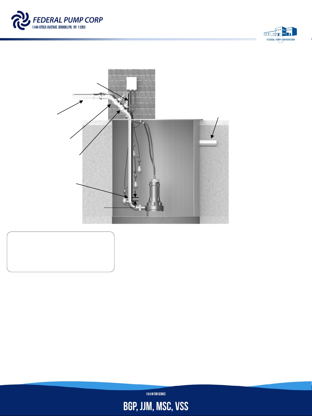
TYPICAL PRE-PACKAGED DUPLEX
SEWAGE SYSTEM SHOWN WITH
FRAME, COVER AND BASIN.
(VALVING AND NOT INCLUDED)
2
DISCHARGE
VENT
INLET
GATE VALVE
CHECK VALVE
Drill 1/8” Dia. Vent hole
to prevent air lock
6.00”

3
Before installation, read the following instructions
carefully. Failure to follow instruction and safety
information could cause serious bodily injury,
death and/or property damage. Each Federal
Pump product is carefully inspected to insure
proper performance. Closely following these
instructions will eliminate potential operating
problems, assuring years of trouble-free service.
IDANGER: "Danger" indicates an imminently
hazardous situation which, if not avoided, WILL
result in death or serious injury.
IWARNING: "Warning" indicates an imminently
hazardous situation which, if not avoided, MAY
result in death or serious injury.
ICAUTION: "Caution" indicates a potentially
hazardous situation which, if not avoided, MAY
result in minor or moderate injury.
IMPORTANT!!! –Federal Pump is not responsible
for losses, injury or death resulting from failure to
observe these safety precautions, misuse, abuse
or misapplication of the pump(s) or equipment.
ALL RETURNED PRODUCTS MUST BE
CLEANED, SANITIZED, OR
DECONTAMINATED PRIOR TO SHIPMENT, TO
INSURE EMPLOYEES WILL NOT BE EXPOSED TO
HEALTH HAZARDS IN HANDLING SAID MATIERAL.
ALL APPLICABLE LAWS AND REGULATIONS SHALL
APPLY.
IWARNING: Installation, wiring, and junction
connections must be in accordance with the
National Electric Code and all applicable state and
local codes. Requirements may vary depending on
usage and location.
IWARNING: Installation and servicing is to be
conducted by qualified personnel only.
Keep clear of suction and discharge
openings. Do not insert fingers in pump
suction with power connected; the rotating cutter
and /or impeller can cause serious injury.
Always wear eye protection when working
on pumps. Do not wear loose clothing that
may become entangled in moving parts.
IDANGER: Pump build up heat
and pressure during operation.
Allow time for pumps to cool before handling or
servicing the pump or any accessory items
associated with or near the pump.
This pump is not intended for use in
swimming pools or water installations
where there is human contact with pumped fluid.
There is a risk of electric shock. To reduce risk of
electric shock, always disconnect pump from
power source before handling any aspect of the
pumping system. LOCK OUT POWER AND TAG.
GENERAL SAFETY INFORMATION
U
`
`
ab
H
••••••••••••••

4
IWARNING: Do not use this pump in water over
104˚F. Do not exceed manufacturer’s
recommended maximum performance, as this
could cause the motor to overheat.
IDANGER: Do not lift, carry or hang pump by the
electrical cables. Damage to the electrical cables
can cause shock, burns, or death. Never handle
connected power cords with wet hands. Use
appropriate lifting device.
IWARNING: Ground Fault Circuit Interrupter
(GFCI) to be used with plug-in type power cord.
IWARNING: Sump and sewage pumps often
handle materials which could cause illness or
disease. Wear adequate protective clothing when
working on a used pump or piping. Never enter a
basin after it has been used.
IDANGER: Failure to permanently ground the
pump, motor and controls before connecting to
power can cause shock, burns, or death.
IDANGER: These pumps are not to be installed
in locations classified as hazardous in accordance
with the National Electric Code, ANSI/NFPA 70.
IWARNING: The Uniform Plumbing Code (UPC)
states that sewage systems shall have an audio
and visual alarm that signals a malfunction of the
systems, that are required to reduce the potential
for property damage.
IMPORTANT!!! –Prior to installation, record
Performance(GPM,TDH), Model Number, Record
Number, Full Load Amp, Voltage, Phase, and HP
from the pump name plate for future reference.
Also record the site voltage and current readings
at equipment startup. Use the table below for
record keeping. Refer to the pump series for
performance data and dimension. The series can
be found as the first group of letters in the “Model
Number”. Contact the factory or local
representative with Record Number for assistance
if needed.
NAME PLATE
GPM: TDH:
Model Number:
Record Number:
Full Load Amp:
Voltage: Phase: HP:
□Oil Fill Motor Design
□Air Fill Motor Design
STARTUP
Voltage:
Amp Draw:
1 Phase L-N:
3 Phase L 1-2:
L 2-3:
L 3-1:
GENERAL SAFETY INFORMATION
••••••••••••••

5
RECOMMENDATIONS
RECEIVING: Immediately upon receipt of the
shipment, inspect and check with the packing list
and report to the transportation company’s local
agent of any damage or shortage. Inspect carton
and wrappings before discarding. Parts and
accessories may sometimes be wrapped
individually and packed in the carton. Should you
find the plastic wrapping removed or damaged
upon the arrival of the equipment, note the
incident on the carrier’s Bill of Lading.
STORAGE: The plastic wrapping is not meant as
mean to protect the equipment from the
environment during storage. If the pump is
received sometime in advance of when it can be
put into use, it should be inspected, rewrapped or
re-boxed and stored in a dry location. If the pump
is to be stored for a long period of time, rotate the
pump shaft periodically to protect the bearings.
Units should not be stored where temperatures
will be below 20˚F or above 100˚F.
CONTROLS: 3 Phase, pump only, and non-115Volt
pump models require a separate approved pump
control device or panel for automatic operation.
Be sure that the electrical specification of the
control selected properly match the electrical
specifications of the pump.
SUBMERGENCE: The pump should always be
operated in the submerged condition. The
minimum liquid level should never be less than
above the pump’s volute. The recommended
liquid level would be the height of the pump to
assist with motor cooling.
VENT HOLE: The discharge piping of the pump
should always be drilled with a vent hole(⅛”Ø) at
a height of 6”above the pump discharge to
prevent air locking.
••••••••••••••

6
INSTALLATION
IWARNING: Under no circumstances should
power or sensing cable be pulled while the pump
is being transported or installed. Attach a chain or
rope to the grip or lugging bolt to install the
pump. (certain models of pump will be provided
with stainless steel lift cable)
1. This pump must not be installed on its side or
operated in a dry condition. Ensure that it is
installed upright on a secure base.
2. Install the pump at a location in the tank
where there is the least turbulence.
3. If there is a flow of liquid inside the tank,
support the piping where appropriate. Install
piping so that air will not be entrapped. If
piping must be installed in such a way that
air pockets are unavoidable, install an air
release valve wherever such air pockets are
most likely to develop.
INSTALLATION: These pumps are recommended
for use in a concrete pit or basin. The basin or lift
station shall be sealed and vented in accordance
with local plumbing codes. This pump is designed
to pump grey water, non-explosive and non-
corrosive liquids, and shall NOT be installed in
locations classified as hazardous in accordance
with the National Electrical Code (NEC)
ANSI/NFPA 70 or Canadian Electric Code (CEC).
The minimum depth should be at least 42”. Check
the pump catalog for minimum basin diameter.
These are the minimum requirements. The pump
should never be installed in a trench, ditch, or
hole with a dirt bottom. The legs will into the dirt
and the suction will become plugged.
1. EXCAVATION: Excavate the hole large enough
to accommodate basin, back fill material, &
adequate working space. A minimum of 8”
diametrical clearance around the tank is
recommended. Never place basin directly in
contact with rocks or other sharp objects.
Prepare the bottom of the excavated hole
with at least 6”of back fill material or
concrete pad. Place only fine ⅛” to ¾” pea
gravel or ⅛” to ½” washed, crushed stone as
back fill material. Do not use sand or native
soil as backfill. Properly compact underneath
the basin to provide a solid level base that can
support the weight of the filled basin. Check
base to insure it is level. Anchor if necessary.
2. INLET CONNECTION & INITIAL BACKFILL: Only
fine pea gravel or washed, crushed stone
should be used around the bottom of the
basin to hold it in place. Concrete may be
poured around basin bottom if ballast is
required for buoyancy. Do not use sand or
native soil as backfill. Make the inlet
connection as required for your basin. Do not
install more than 1 inlet connection per basin.
3. FINAL BACKFILL: Fill basin with water before
backfilling. Only fine pea gravel or washed,
crushed stone is recommended. Do not use
sand or native soil as backfill. Back fill to 4”to
6”around the entire periphery of the basin.
Compact back fill material in 12”lifts.
ICAUTION: If burial depth is greater than basin
height, consult factory representative to assure
structural integrity is not compromised.
Reinforcement may be required
ICAUTION: In freezing conditions, back fill
material must be dry and free of ice.
••••••••••••••

7
INSTALLATION
DISCHARGE PIPING: Discharge piping should be as
short as possible and sized no smaller than the
pump’s discharge size. Do not reduce the
discharge pipe size below that which is provided
on the pump. Both check valves and a shut-off
valve are recommended for each pump. The
check valve is used to prevent backflow into the
pit. If a swing check valve is used, it is
recommended to be installed at a 45°agree with
the pivot pin on top. The shut-off valve is used to
manually stop system flow during pump testing
and servicing.
ELECTRICAL CONNECTIONS:
1. POWER CABLE: The power cable mounted to
the pump must not be modified in any way
except for shortening or splicing to a specific
applications. 1 Phase pumps are provided with
a 3 wire power cord, and 3 Phase pumps are
provided with a 4 wire power cord. Connect
the green wire to ground. Under no
circumstances should the green wire be
connected to the power supply. Every pump
must be grounded. DO NOT USE THE POWER
CABLE TO LIFE PUMP. Do not use an
extension cord for 1 Phase pump(s). Always
wire the pump as indicated on the wiring
diagram inside the control panel
2. OVERLOAD PROTECTION: On submersible
motors, an in-panel overload protector is
needed to act as an overheating protector and
operates on the combined effect of
temperature and current. This means that the
overload protector will trip out and shut the
pump off if the windings become too hot, or
the load current passing through them
becomes too high. (IMPORTANT!!! –The
overload in the panel should NOT
automatically reset and start the pump up
after the motor cools.) In the event of an
overload, the source of this condition should
be determined and corrected immediately.
IWARNING: Never let the end of the cable
contact water
IWARNING: If the cable is extended, do not
immerse the splice in water
ICAUTION: Fasten the cable to the discharge
piping with zip tie
ICAUTION: Install the power cable so that it will
not overheat. Overheating is typically caused by
coiling the cable and exposing it to direct sunlight.
IMPORTANT!!! Always rely on a Certified
Electrician for installation
••••••••••••••

8
INSTALLATION
LIQUID LEVEL CONTROL (1Ph/230V & 3Ph):
Refer to the figure 1 which shows a typical
installation of (2) 1 phase 230 volt and 3 Phase
pump at all voltage using (3) level control switches
(SW1, SW2, SW3) and (1) high water alarm switch
(SW4) mounted to the style 1 pilot device with a
duplex control panel. The level control and high
water alarm float should have adequate clearance
so they cannot hang up in their swing and that the
pump is completely submerged when the level
controls are in the “OFF” mode. By adjusting the
cord tether the control levels can be changed.
Figure 1
••••••••••••••

9
OPERATION
PRE-OPERATION: After completing installation,
perform the following prior to contacting Federal
Pump’s local representative for equipment start
up:
1. CHECK VOLTAGE AND PHASE: Compare the
voltage and phase information stamped on
the pump name plate.
2. CHECK PUMP ROTATION: Improper motor
rotation can result in poor pump performance
and can damage the motor and/or pump.
Incorrect rotation for 1Phase pumps is
unlikely. If the rotation is incorrect contact
factory.
3. NAME PLATE: Record the information from
the pump name plate for future reference.
4. INSULTATION TEST: An insulation (megger)
test should be performance on the motor
before the pump is put into service. The
resistance values, voltage, and current should
be recorded.
5. PUMP-DOWN TEST: Be sure pump has been
properly wired, lowered into the basin or lift
station. Check the system by filling the pit with
liquid and allowing the pump to operate
through its pumping cycle if control system is
ready. Otherwise, test the pump on “HAND”
or manual position (make sure the liquid level
does not get pump below the top of the pump
volute. The time needed to empty the system
(pump-down time) along with the volume of
water, should be recorded. Pump are typically
designed to operate up to 20 cycles an hour.
SEQUENCE OF OPERATION: For Federal Pump’s
Since Federal Pump offers a multitude of liquid
level controls, please refer to their (OS, FSS, SBS,
TCS, NPC) corresponding IOM manual for
sequence of operation
••••••••••••••
10
OPERATION
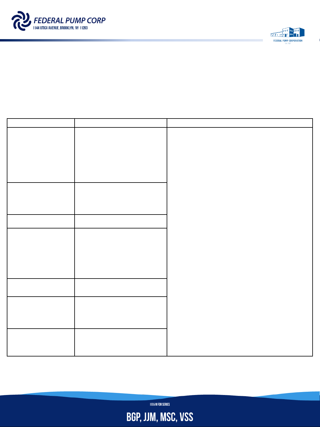
TROUBSHOOTING CHART: Always disconnect the pump from the power source before handling
inspections or repairs .
HCAUTION: Risk of electric shock
`DANGER: Keep clear of suction and discharge openings. Do not insert fingers in pump with power
connected; the rotating cutter and /or impeller can cause serious injury.
SYMPTOM
POSSIBLE CAUSE(S)
CORRECTIVE ACTION
Pump will not run
1.
Poor electrical connection, blown fuse(s), tripped
breaker or other interruption of power; improper
power supply
2.
Motor or switch inoperative (go to manual
operation)
2a.
Float movement restricted
2b.
Switch will not activate pump or is defective
2c.
Defective or damaged motor
3.
Insufficient liquid level
16.
Liquid temperature exceeding pump operation
range
1.
Check all electrical connections for security. Have electrician measure current in
motor leads, if current is within ±20% of locked rotor Amps, impeller is probably
locked. If current is 0, overload may be tripped on a single phase pump. Remove
power, allow pump to cool, then re-check current
2a.
Reposition pump or clean basin as required to provide adequate clearance for float
2b.
Disconnect level control. Set ohmmeter for low range, such as 100 ohms full scale
and connect to level control leads. Actuate level control manually and check to see
that ohmmeter shows zero ohms for closed switch, and full scale for open switch.
2c.
Check winding insulation and winding resistance. If check is outside of range, dry and
re-check. If still defective, replace per maintenance instruction for the pump series.
3.
Mark sure liquid level is above the pump
4. Re
-check all sizing calculations to determine proper pump sizing
5. Check discharge line for restrictions, including ice if line passes through or into cold
areas.
6.
Remove and examine check valve for proper installation and freedom of operation
7. Open valve
8. Check impeller for free of operation, security and condition. Clean impeller cavity
and inlet of any obstruction
9.
Loosen flange or union slightly to allow trapped air to escape at the discharge piping
slowing while the pump is on “HAND”. Clean vent hole
10.
Check rotation. If power supply is three phase, reverse any (2) of (3) power supply
leads on the motor end of the starter or VFD to ensure proper impeller rotation
11.
Repair fixtures as required to eliminate leakage
12.
Check pump temperature limits and fluid temperature
13.
Replace portion of discharge pipe with flexible connector or tighten existing piping
14.
Turn to automatic position
15.
Check for leaks around basin inlet and outlets
16.
Check temperature of the liquid inside the pit. Quench the basin with a hose to 70˚F,
and let it cool down before turning the pump on. Add a dedicated quench line to the
system to keep the pump from overheating
Pump
will not turn off
2a.
Float movement restricted
2b.
Switch will not activate pump or is defective
4.
Excessive inflow or pump not properly sized for
application
9.
Pump may be air locked causing pump not to flow
14.
H-O-A switch on panel is in “HAND” position
Pump hums but doesn’t run
1.
Incorrect low voltage
8.
Impeller jammed or loose on shaft, or inlet plugged
Pump delivers
insufficient capacity
1.
Incorrect low voltage
4.
Excessive inflow or pump not properly sized for
application
5.
Discharge restricted
6.
Check valve partially closed or installed backwards
7.
Shut-off valve closed
8. Impeller jammed or loose on shaft, or inlet plugged
9.
Pump may be air locked causing pump not to flow
10.
Piping fixtures leaking or discharge before the
nozzle
Pump cycles too frequently or runs
periodically when fixtures are not in use
6.
Check valve partially closed or installed backwards
11.
Fixtures are leaking
15. Ground water entering basin
Pump shuts off and
turns on
independent of switch, (trips thermal
overload protector). CAUTION! Pump
may start unexpectedly. Disconnect
power supply.
1.
Incorrect low voltage
4.
Excessive inflow or pump not properly sized for
application
8. Impeller jammed or loose on shaft, or inlet plugged
12. Excessive water temperature (internal protection
only)
Pump operates noisily or vibrates
excessively
2c.
Worn bearings, motor shaft bent
5.
Debris in impeller cavity or broken impeller
10.
Pump running backwards
13.
Piping attachments to building structure too loose
or rigid.
NOTE: Federal Pump assumes no responsibility for damage or injury due to disassembly in the field. Disassembly of the pumps or supplied accessories other than at Federal Pump or its
authorized service centers, automatically void warranty on the equipment
••••••••••••••

11
MAINTENANCE
INSPECTION: Schedule to check pressure, output,
voltage, current, and other specifications on a bi-
annual basis. If unusual readings are found, and
correct as soon as possible.
1. DAILY INSPECTIONS: Check current daily. If the
amp draw fluctuation is great, even though its
within the limits of pump rating, foreign
objects may be clogging the pump. If the
amount of liquid discharged falls suddenly,
said objects may block the suction inlet.
2. MONTHLY INSPECTIONS: Measure the
insulation resistance. The value should be
more than 1M ohm. If resistance starts to fall
rapidly even with an initial indication of over
1M ohm, this may be an indication of damage
or defect and repair work would be required.
3. ANNUAL INSPECTIONS: To extend the service
life of the mechanical seal, replace the oil in
the mechanical seal chamber (for applicable
SERIES) once a year. Water mixed with the oil
or cloudy textures are indications of a
defective mechanical seal requiring
replacement. When replacing the oil, lay the
pump on its side with filler plug on top. Inject
suitable amount of oil. Not every pump has an
oil chamber. Refer to sectional view for
details.
4. 3-5 YEAR INSPECTIONS: Conduct an overhaul
on the pump. These intervals will preclude the
possibility of future trouble.
5. COOLING OIL INSPECTION: Anytime the pump
removed from operation, the cooling oil in the
motor housing should be checked visually for
oil level and contamination. To check oil, set
unit upright, remove pipe plug from housing,
and inspect the oil in the housing to make
sure it is clean and clear (light amber in color
and free from suspended particles). Milky
white oil indicates the presence of water. Oil
level should be just above the motor when
pump is in vertical position.
SERVICE: No periodic lubrication is required.
Perform the following checks every time a pump
is removed from operation or when pump
performance deteriorates:
1. Inspect motor chamber for oil level and
contamination
2. Inspect impeller and body for excessive build-
up of clogging
3. Inspect motor, bearings, and shaft seal for
wear or leakage
OIL TESTING: Test the cooling oil using the
following steps
1. Drain oil into a clean, dry container by placing
pump on its side, and removing pipe plug from
housing.
2. Check oil for contamination using an oil tester
with a range to 30kV breakdown.
3. If oil is found to be clean and uncontaminated
(measuring above 15kV), refill the housing
with the same oil
4. If oil is found to be contaminated (measuring
15kV or below), the pump must be carefully
inspected for leaks at the shaft seal, cable
assembly, gaskets, and pipe plug. To help
locate the leak(s), perform a “soap bubble”
leak test
5. After leak is repaired, dispose of old oil
properly, and refill with new oil.
••••••••••••••

12
MAINTENANCE
PRESSURE TEST (IF OIL HAS BEEN DRAINED):
Remove pipe plug from housing. Apply pipe
sealant to pressure gauge assembly and tighten
into hole. Pressure motor housing to 10 PSI. Use
solution around the sealed areas and inspect
joints for air bubbles
If, after five minutes, the pressure is still holding
contact, and no bubbles are observed, slowly
bleed the pressure and remove the gauge
assembly, and replace oil. All leak(s) must be
located and repaired if pressure does not hold.
PRESSURE TEST (IF OIL HAS NOT BEEN DRAINED):
Oil should be at normal level. Remove pipe plug
from housing. Apply pipe sealant to pressure
gauge assembly and tighten into hold. Pressurize
motor housing to 10 PSI. Use soap solution
around the sealed areas above the oil level and
inspect joints for air bubbles. For sealed areas
below oil level, leaks will seep oil. If, after five
minutes, the pressure is still holding constant, and
no bubbles, oil seepages is observed, slowly bleed
the pressure and remove the gauge assembly, and
replace oil. All leak(s) must be located and
repaired if pressure does not hold.
PRESSURE TEST (AIR FILL MOTOR)
Remove pipe plug from housing. Apply pipe
sealant to pressure gauge assembly and tighten
into hold. Pressurize housing to 10 PSI. Use soap
solution around the sealed areas to inspect joins
for air bubbles. If, after five minutes, the pressure
is still holding constant, and no bubbles, slowly
bleed the pressure and remove the gauge
assembly, and replace pipe plug. All leak(s) must
be located and repaired if pressure does not hold.
ICAUTION: Pressure builds up extremely quickly
due to the limited space inside the pump housing.
Too much pressure will damage mechanical seal.
DO NOT exceed 10 PSI
OIL REPLACEMENT: Set unit upright and refill with
new cooling oil as per table below. Fill to just
above motor, but below capacitor(1Phase motor)
as an air must remain in the top of the housing to
compensate for oil’s thermal expansion. Apply
pipe thread compound to threads of pipe plug
then assemble it to housing.
DANGER: DO NOT overfill oil.
Overfilling of housing with oil will
create excessive and dangerous hydraulic pressure
which can destroy the pump and create a hazard.
Overfilling oil voids equipment warranty
ib
Cooling Oil
Recommended Supplier/Grade
BP Enerpar SE100
Conoco Pale Parafin 22
Mobile D.T.E Oil Light
Shell Transformer-10
Texaco Diala-Oil-AX
••••••••••••••

13
MAINTENANCE
DISASSEMBLY: When disassembling pump, have a
piece of cardboard or wooden board ready to
place the different parts on as you work. Do not
pile parts on top of each other. They should be
laid out neatly in rows. The O-ring and gasket
cannot be reused once they are removed. Have
replacement parts ready prior to disassembly.
Disassemble in the order shown below, while
referring to the sectional view in the equipment
catalog. Always disconnect power prior to
dissembling the pump.
1. IMPELLER & VOLUTE:
a) Remove cap screws, volute and gasket.
b) Clean and examine impeller for cracks
or chips, and replace if required. To
remove impeller, place a flathead
screwdriver in the slot at the end of
the shaft to hold the shaft stationary
while unscrewing.
c) Where applicable, check v-ring and
remove if damaged.
2. POWER CORD & MOTOR:
a) Place pump upright on blocks to avoid
resting unit on shaft.
b) Remove pipe plug and drain oil from
housing.
c) Remove gland nut and washer from
the motor housing, and slide power
cord up along with washers and
grommet.
d) Pull cord through and disconnect the
wires from the terminals on power
cord. Be sure to note wire connections
for reassembly.
e) Disconnect cable leads from motor
leads and remove motor housing and
O-ring. Always replace O-ring and
gasket once removed.
f) For single phase motors, check motor
capacitor with an Ohmmeter by first
grounding the capacitor by placing a
screwdriver across both terminals. If
the Ohmmeter reading moves to
infinity then drifts back, the capacitor
is in working condition. Otherwise,
replace the capacitor.
g) Inspect motor winding for shorts, and
check resistance valves. Check rotor for
wear and damages. If rotor or the
stator windings are defective or
damaged, the complete motor must be
replaced.
3. MECHANICAL SEAL:
a) Where applicable, remove seal plate.
b) Carefully remove mechanical seal
without scratching sliding surface
c) Inspect for signs of uneven wear
pattern on stationary members, chips
and scratches on either seal faces.
Replace the complete seal if any part is
damaged. DO NOT interchange seal
components. Replace the entire shaft
seal.
4. BEARING:
a) Examine bearing and replace if worn.
Remove bearing from shaft using a
wheel puller, if replacement is
required.
••••••••••••••

14
MAINTENANCE
ASSEMBLY: All parts must be clean before
reassembly. Handle seal parts with extreme care.
DO NOT damage lapped surfaces. Reassemble in
reverse order of disassembly. Be careful of the
following:
1. During reassembly, periodically. rotate the
impeller by hand and check for smooth
rotation. If rotation is not smooth, check for
alignments in the bearing, and scratches on
the seal faces.
2. Upon completion of reassembly, rotate the
impeller by hand from the pump suction, and
check that it rotates smoothly without
touching the suction plate before operating
the pump.
O-rings, shaft seals, gaskets, and other pump
components are available as kits from the factory
and representatives.
••••••••••••••

15
NOTES
••••••••••••••

Federal Pump Corporation
Factory Warranty
Equipment or parts manufactured by Federal Pump Corporation (“Seller”) which fail to function
properly because of defects in material or workmanship and which are returned to Seller with
shipping charges prepaid, within one year from date of shipment (invoice date) will be repaired
or replaced by Seller, FOB the factory, at Seller’s expense. Equipment or parts furnished by
Seller, but manufactured by others (such as motors, switches, control panels, etc.) are the
responsibility of the manufacturer under its warranty, if any, and Buyer’s sole recourse will be
to such manufacturer. If Seller determines that the failure to function properly (of equipment
or parts returned) is not due to defective material or workmanship but rather to misapplication
or mishandling after receipt by Buyer, Seller will repair or replace the equipment or parts upon
Buyer’s authorization, and bill Buyer for material and labor required for the repair or
replacement. The forgoing sets forth Seller’s only warranty with respect to, and Seller’s entire
liability, for any claim or damages whatsoever arising out of the supplying of the equipment
hereunder or its use. The foregoing warranty is made by Seller and accepted by the person to
whom Seller’s applicable invoice is directed (“Buyer”) in lieu of all other warranties, express or
implied, of Seller and in lieu of all other obligations or liabilities of Seller. No other
representation or warranty on the part of seller, express or implied, shall apply to the
equipment supplied hereunder or referred to herein, or to its performance, all such other
warranties (including any warranty of merchantability or fitness for any purpose) being hereby
disclaimed. In no event will Seller be responsible for loss of business or profits or any other
similar or dissimilar consequential or incidental damages or losses. If warranty repairs or
replacements of parts are to be accomplished locally in lieu at Seller’s factory, they must be
agreed to in writing, by Seller in advance of the work being done, and with the exact cost of the
work stated in a letter of authorization from Seller. No expenses incurred will be paid by Seller
unless so agreed to in advance. Seller’s standard warranty extends for twelve months from
date of shipment. If the standard warranty is to be extended to eighteen months from date of
shipment, add 6% to the purchase price of the equipment. If the standard warranty is to be
extended to twenty-four months from the date of shipment, add 12% to the purchase price of
the equipment. If the standard warranty is to be extended to thirty months from date of
shipment, add 18% to the purchase price of the equipment. If the standard warranty is to be
extended to thirty-six months from date of shipment, add 24% to the purchase price of the
equipment. Extended warranties are effective only if the equipment is properly stored and
adequately protected from weather, excessive condensation, atmospheric conditions and
physical damage, and only if the equipment has been properly installed and not misused or
mishandled.
If you have a claim under the provision of the warranty, contact Federal
Pump Corporation or your local authorized representative.
This manual suits for next models
7
Table of contents
Popular Water Pump manuals by other brands


Giant
Giant MP Series Operating instructions/ repair and service manual

Burks
Burks BPV Series Installation and operation manual

BOC Edwards
BOC Edwards STP-A2203 Series instruction manual

Agilent Technologies
Agilent Technologies TPS-mobile 9698400 user manual

Warren rupp
Warren rupp WR10 operating instructions

Becker
Becker VXLF 2.200 operating instructions