Federal Signal Corporation 154XST Quick guide

MODEL 154XST
INSTALLATION AND SERVICE INSTRUCTIONS FOR MODEL 154XST
STROBE LIGHT FOR USE IN HARSH ENVIRONMENTS/
HAZARDOUS LOCATIONS
2561762B
REV. B 210
Printed in U.S.A.

INSTALLATION AND SERVICE INSTRUCTIONS FOR MODEL 154XST STROBE LIGHT
FOR USE IN HARSH ENVIRONMENTS/HAZARDOUS LOCATIONS
SAFETY MESSAGE TO INSTALLERS, USERS AND MAINTENANCE PERSONNEL
It is important to follow all instructions shipped with this product. This device is to be installed by a
trained electrician who is thoroughly familiar with the National Electrical Code and will follow the
NEC Guidelines as well as local codes.
The selection of the mounting location for the device, its controls and the routing of the wiring is to
be accomplished under the direction of the facilities engineer and the safety engineer. In addition,
listed below are some other important safety instructions and precautions you should follow:
•Readandunderstandallinstructionsbeforeinstallingoroperatingthisequipment.
•Donotconnectthislighttothesystemwhenpowerison.
•Afterinstallation,ensurethatthesetscrewisproperlytightenedandthatthreadedjointsarefully
engaged.
•Afterinstallation,testthelightsystemtoensurethatitisoperatingproperly.
•Aftertestingiscomplete,provideacopyofthisinstructionsheettoalloperatingpersonnel.
•Establishaproceduretoroutinelycheckthelightinstallationforintegrityandproperoperation.
Failure to follow all safety precautions and instructions may result in property damage, serious
injury,ordeathtoyouorothers.
I. GENERAL.
The Model 154XST Strobe Light is a UL listed visual signal for hazardous and marine locations
and has been investigated by UL as meeting Type 4X (water tight and corrosion resistant) enclo-
surerequirements.Itprovidesabout80high-intensityashesperminute.Theeffectivecandle-
power (ECP) of the light is 165 with a clear globe installed. The unit is available for 12 through
24VDC.
II. INSTALLATION.
A.Unpacking.
WARNING
Damagedglobescanleadtoexplosionswhichcouldresultinseriousinjuryordeath.
AfterunpackingtheModel154XST,examineitfordamagethatmayhaveoccurredintransit.If
theequipmenthasbeendamaged,donotattempttoinstalloroperateit,leaclaimimmediately
withthecarrierstatingtheextentofthedamage.Carefullycheckallenvelopes,shippinglabels
and tags before removing or destroying them.
B. Mounting.
CAUTION
Toreducetheriskofreorexplosion,donotinstallinahazardouslocationiftheoperatingtempera-
ture(seetable1)exceedsthehazardousatmosphere’signitiontemperature.
Beforeproceeding,usetable1asaguideanddeterminethattheunit’soperatingtemperature
DOESNOTexceedthehazardousatmosphere’signitiontemperature.
For marine applications, all wiring including supply wire must be stranded wire and meet the
USCG(CFR46)Sections(110-113).
TheModel154XSThasprovisionsformountingto3/4"pipeandmaybemountedinany
position. Before mounting, ensure that mating threads are clean. To prevent the ingress of water
and dust, apply conductive sealant to the conduit threads prior to mounting. If non-conductive
sealantisused,theenclosuremustbeearthedviatheprovidedinternalgroundingwire/ground-
ing screw to ensure proper grounding continuity. In high-humidity environments when units are
-1-

mounted dome down, condensation may occur in the conduit system. Use properly rated conduit
seals/drainstopreventmoisturefromenteringthexture.Threadthextureontothe3/4"pipe
and secure with the set screw.
Thedomeguard(Part#K8449090)maybeusedasanaccessory.Itismountedonthe154XST
usingthetwosupplied#8-32screws.Adjustthetensiononthescrewsuntilthedomeguardis
squarewiththehousing.
C. Electrical Connections.
WARNING
This is a four-wire device, and when installed, all four wires must be terminated. Failure to terminate
bothredandbothblackwireswillresultinashockorrehazard.
The 154XST unit is provided with four leads; two red, and two black. To achieve electrical
supervision, connect one red (+) lead to the positive side of the incoming power source and the
other red (+) lead to the outgoing power source. Likewise, connect one black (–) lead to the
negative side of the incoming power source, and the other black (–) lead to the negative side of
the outgoing power source.
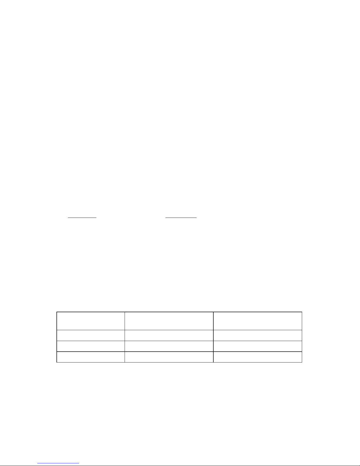
Ifrequired,thegreenscrewinthehousingisprovidedforconnectiontoanearthground(see
gure1).Togainaccesstothescrew,thepowersupplyassemblycanberemoved.Globe
removalisdescribedinparagraphIII.A.1.
NOTE
This unit is polarity sensitive, and may be damaged by incorrect electrical hookup. Polarity must be
observedforproperoperation.Inaddition,damagewillresultifthevoltageratingisexceeded.
III. MAINTENANCE.
WARNING
Topreventignitionofhazardousatmospheres,disconnectthexturefromthesupplycircuit
before opening. Keep tightly closed when in operation.
SAFETY MESSAGE TO MAINTENANCE PERSONNEL
Listed below are some important safety instructions and precautions you should follow:
• Readandunderstandallinstructionsbeforeoperatingthissystem.
• Anymaintenancetothelightsystemmustbedonewiththepowerturnedoff.
• Anymaintenancetothelightsystemmustbeperformedbyatrainedelectricianinaccordancewith
NEC Guidelines and local codes.
• Neveraltertheunitinanymanner.Safetyinhazardouslocationsmaybeendangeredifadditional
openingsorotheralterationsaremadeinunitsspecicallydesignedforuseintheselocations.
• Thenameplate,whichmaycontaincautionaryorotherinformationofimportancetomaintenance
personnel,shouldnotbeobscuredifexteriorofhousingsusedinhazardouslocationsarepainted.
• Brokenglobescanleadtoexplosionswhichcouldresultinseriousinjuryordeath.Iftheglobeis
damaged in any way, the complete globe assembly MUST be replaced.
• Theonlyelectricalcomponentstobereplacedbythecustomeraretheashtubeandthecircuit
board assembly.
A. Flash Tube Replacement.
Asstrobelightsareused,theashtubesbegintodarken,causingthelightoutputtodecrease.
Thisdarkeningischaracteristicofashtubes.Darkeningwillbeginnearthebaseofthetube
andprogressupward.Also,asashtubesage,theymayhaveatendencytomisre(notre
periodically).
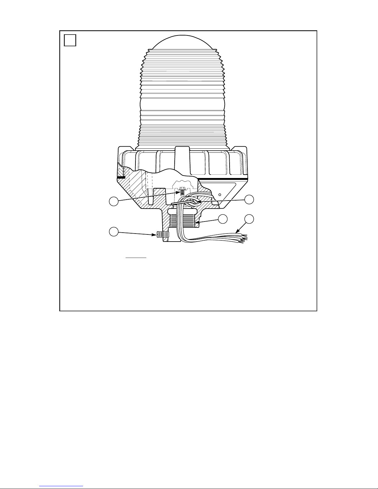
Afterextendedoperation,occasionallycheckforashtubedegradation.Shouldtheashtube
misre,haveanoticeabledecreaseinlightoutput,glowcontinuouslyordarkentoapoint
beyondthatshowningure2,itshouldbereplaced.
-2-

WARNING
High voltages are present inside the light assembly. Wait at least 5 minutes after shutting off
the power before servicing this unit.
Tochangetheashtube,proceedasfollows:
1. To remove the globe assembly, grasp the metal ring attached to the globe and turn it counter-
clockwise. If the globe assembly will not unscrew, place a screwdriver blade against one of
the four bosses on the metal ring attached to the globe. Gently tap the screwdriver handle to
loosen the globe assembly from the base casting.
WARNING
To maintain effectiveness of hazardous location enclosure, do not damage globe or threads while
disassemblingorreassemblingunit.Lubricatedthreadedjointsexposedforlongperiodsoftimemay
attractsmallparticlesofdirtorotherforeignmaterials.Bodyandcoverjointsshouldbereassembled
immediately, with all threads fully engaged.
2. Withthegloberemoved,gentlypulltheashtubefromitssocket.Arockingmotionismost
helpful when installing or removing the tube.
3. ReplacetheashtubewithFederalSignalPartNo.K149122.Ensurethatthereplacement
tube is fully seated in the socket.
4. Replacetheglobeassembly.Ensurethattheglobeassemblyisseatedsecurelyagainstthe
gasket.
5. Test the light for proper operation.
B. Power Supply Replacement.
WARNING
High voltages are present inside the light assembly. Wait at least 5 minutes after shutting off the
power before servicing this unit.
1.RemovetheglobeassemblyasdescribedinparagraphIII.A.1.
2.Removeandretainthescrewwhichsecuresthepowersupplycircuitboardtothehousing.
3.Disconnectthepowerconnectorfromtheoldpowersupplyandconnectittotheconnectoron
the new power supply.
NOTE
Ensure that the connector is fully seated on the circuit board connectors.
4. Secure the new power supply to the housing with the previously removed screw.
5. Installthenewashtubeinthesocket.Ensurethattheashtubeisfullyseatedinthesocket.
6. Replacetheglobeassembly.Ensurethattheglobeassemblyisseatedsecurelyagainstthe
gasket.
7. Test the light for proper operation.
C. Cleaning Enclosure.
NOTE
Maintenanceproceduressometimesrequirexturestobehoseddownforgoodhousekeeping.
Thextureshouldbecleanedperiodicallytomaintainmaximumlightoutput.Onlymild,non-
abrasivecleaningagentsshouldbeused.Thewaterforceappliedbyahosemustnotexceed65
gallonsperminutefroma1"diameterhoseatadistanceof10feet.Theglassglobeshouldbe
regularly inspected for scratches and chips, and, if damaged, must be replaced.
D. Lubrication.
Threadedjointsshouldbewelllubricatedwithpetroleumorasoap-thickenedmineraloil.If
corrosiveproductshaveaccumulatedonjointsandcannotreadilyberemovedwithsolvents,the
parts should be discarded and replaced.
-3-

WARNING
Neveruseanabrasivematerialorletoremovecorrosiveproductsfromthreadedsurfaces.In
extremelycorrosivelocations,equipmentshouldbeperiodicallyinspectedtoguardagainstunusual
deterioration and possible porosity, since this may weaken the enclosure structurally.
E. Service.
TheFederalfactorywillserviceyourequipmentorprovidetechnicalassistancewithanyprob-
lems that cannot be handled locally.
AnyunitsreturnedtoFederalSignalforservice,inspection,orrepairmustbeaccompanied
byaReturnMaterialAuthorization.ThisR.M.A.canbeobtainedfromthelocalDistributoror
Manufacturer’sRepresentative.
Atthistimeabriefexplanationoftheservicerequested,orthenatureofthemalfunction,should
be provided.
Addressallcommunicationsandshipmentsto:
FEDERAL SIGNAL CORPORATION
Industrial Systems
ServiceDepartment
2645FederalSignalDrive
UniversityPark,IL60484-3167
708-534-4858(Service)
708-534-3424,extension5823(TechnicalAssistance)
F. Replacement Parts.
Description Part Number
DomeAssembly,Red K8449078
DomeAssembly,Amber K8449078-01
DomeAssembly,Blue K8449078-02
DomeAssembly,Green K8449078-03
DomeAssembly,Clear K8449078-04
Gasket K8449080
PowerSupplyAssy.,12-24VDC K2001173
FlashTube K149122
DomeGuard K8449090
-4-
Table 1.
Hazardous
Environment
Max.Temperature/ULTempera-
tureCodeat40°CAmbient
Max.Temperature/ULTempera-
tureCodeat66°CAmbient
ClassI,Division2 260°C/T2B 300°C/T2
Class II, Groups E, F, G 100°C/T5 100°C/T5
Class III 100°C/T5 100°C/T5

English
A. Groundscrew(green)
B. 1/4-20setscrew
C. 3/4-14N.P.T.
D. Fieldwiring
E. Wrap power leads once
around washer then pull through casting.
-5-
290A4344
B
A
C D
E
1

English
A.Newashtube(K149122)
B.Usedashtubetendstodiscolorinareasshown,andshouldbereplaced.
290A4375
B
A
2
Industrial Systems
2645 Federal Signal Drive • University Park, IL 60484-3167
Tel: 708-534-4756 • Fax: 708-534-4852
Email: [email protected] • www.federalsignal-indust.com
Table of contents
Other Federal Signal Corporation Floodlight manuals
Popular Floodlight manuals by other brands

PB Lighting Company
PB Lighting Company F180 Series installation manual

Dymond
Dymond BLF-100 instruction manual

RASHA PROFESSIONAL
RASHA PROFESSIONAL Kryos Quick user manual

DIMON TECHNOLOGY
DIMON TECHNOLOGY HAAE instruction manual

Chauvet
Chauvet COLORado Ridge IP Quick reference guide

OmniSistem
OmniSistem Spark 7 Zoom user manual

VIZULO
VIZULO Premium Eagle Mounting instruction

Essential Garden
Essential Garden solar dog specification

Ledj
Ledj Slimline 36 RGBW user manual

Larson Electronics
Larson Electronics HAL-PRM-150W-LED instruction manual

Eterna
Eterna POLY10PIR installation instructions

Integral LED
Integral LED ILEMTS035 Installation instruction sheet