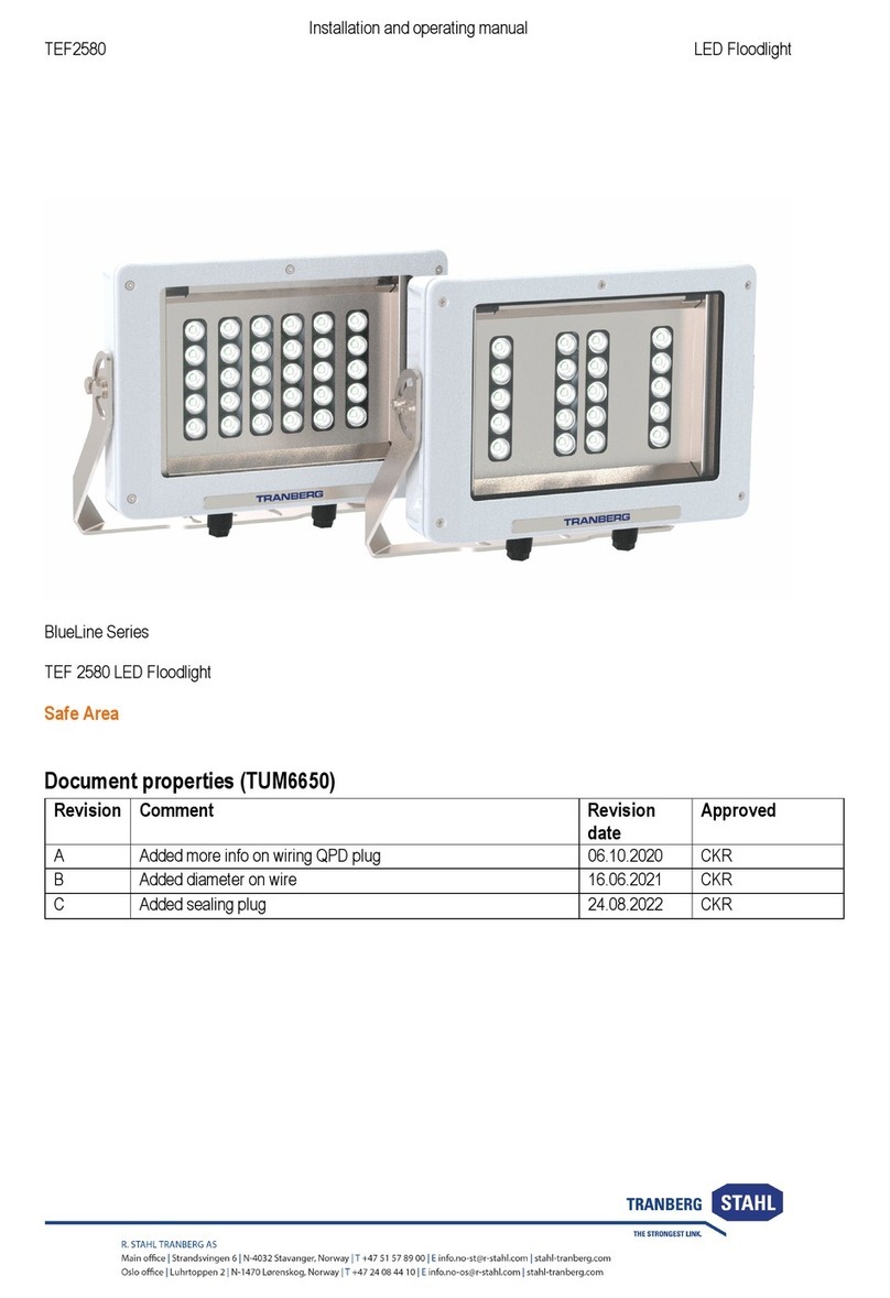
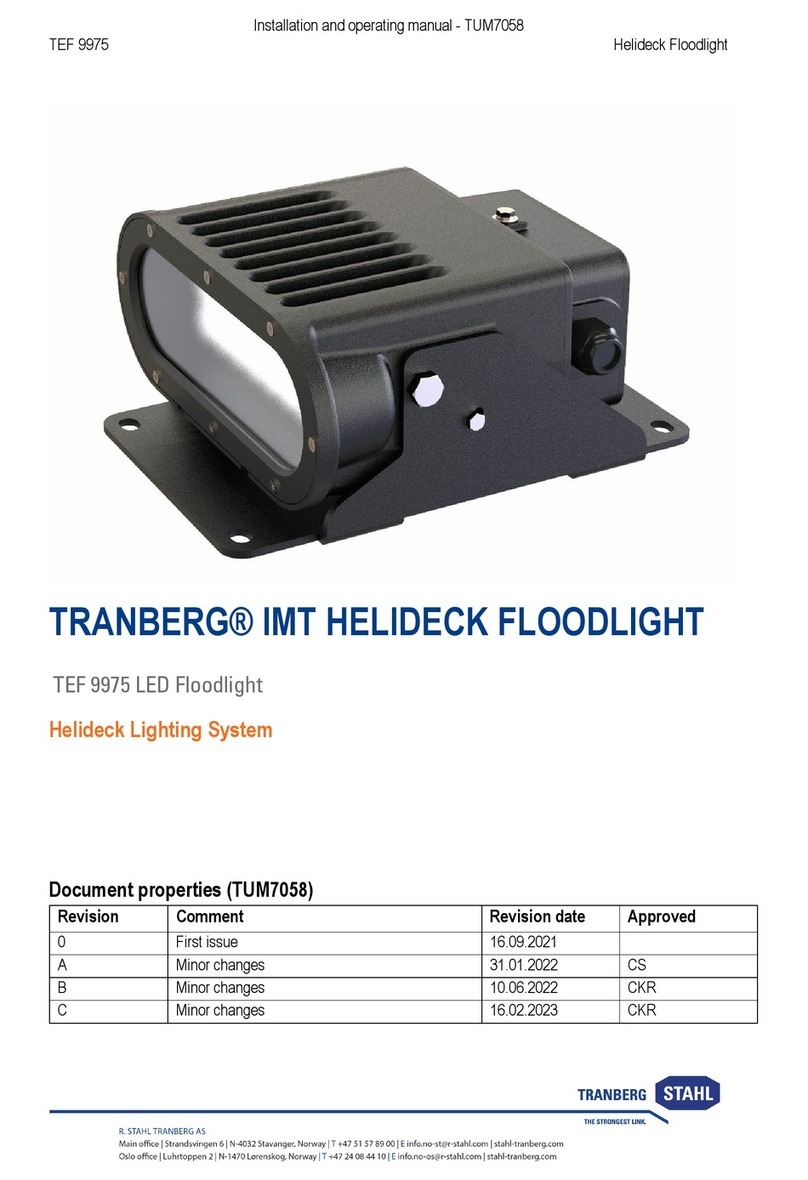
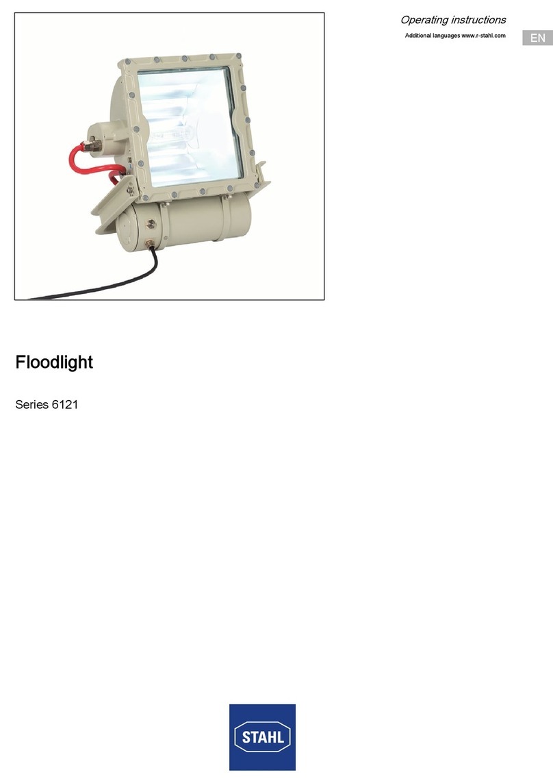
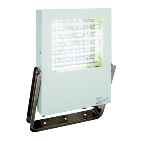
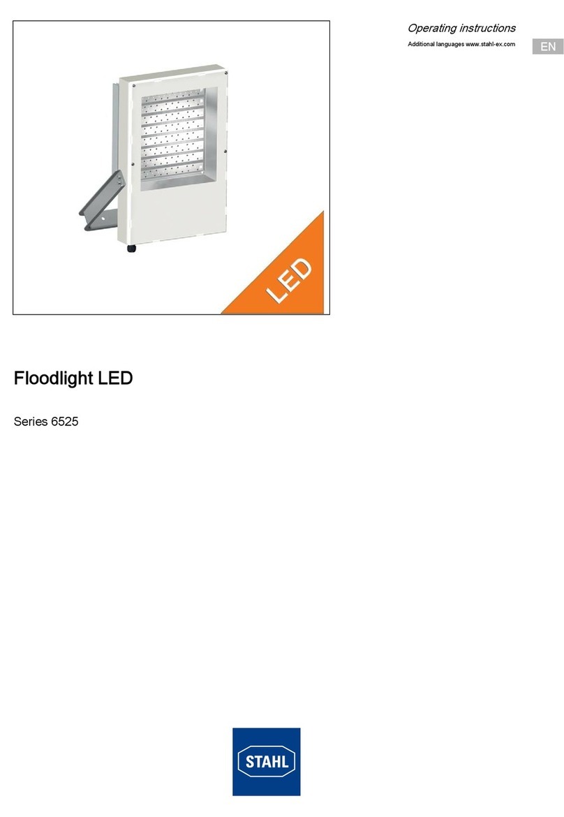
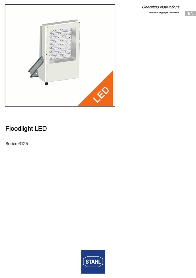
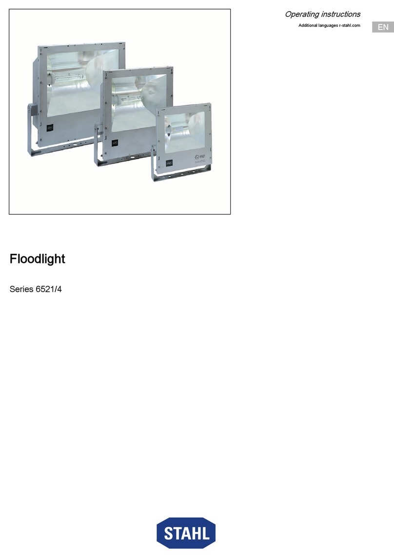
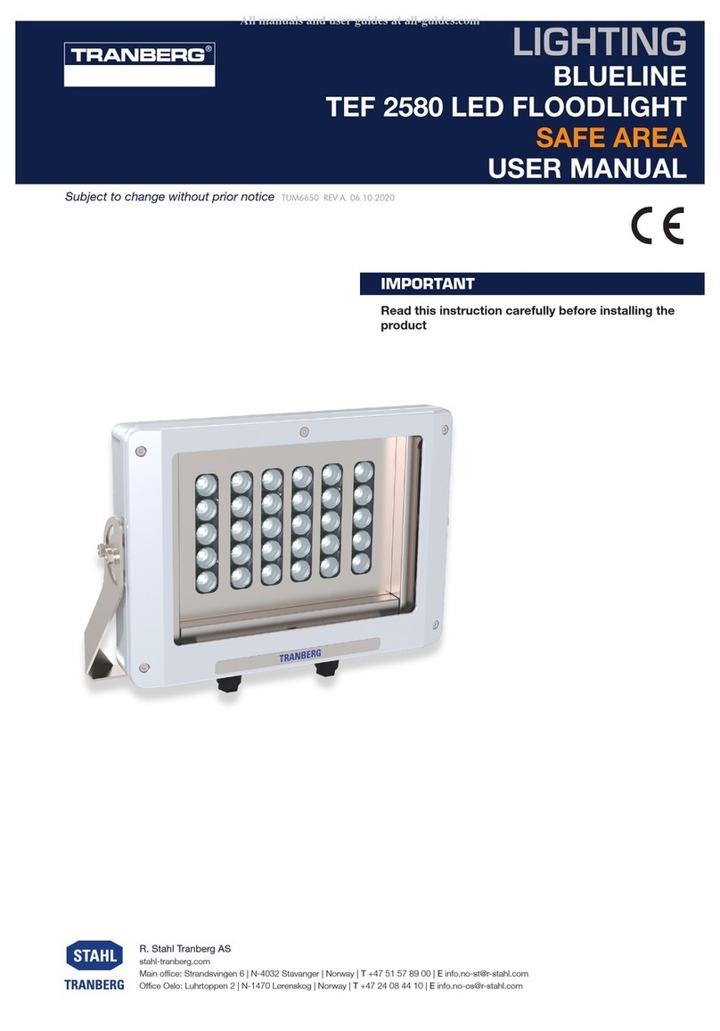
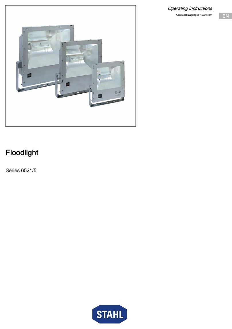
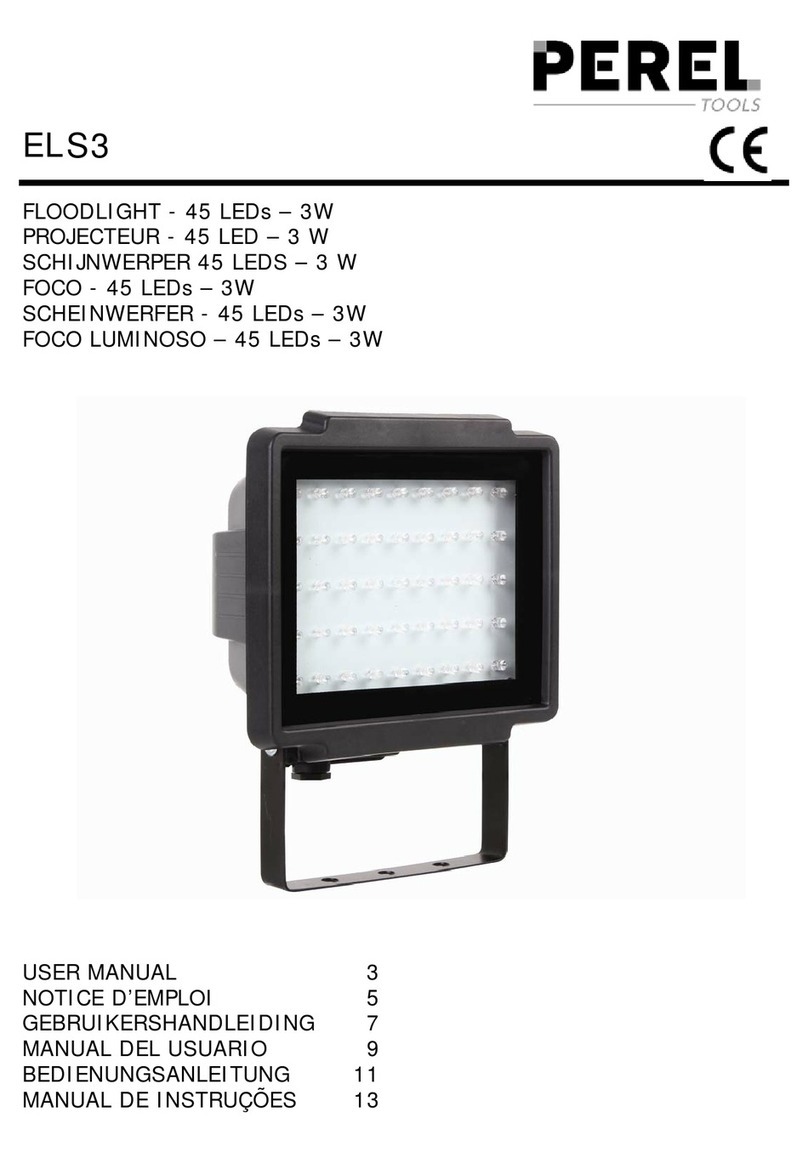
Stahl 6521/4 Series User manual

EN
EN
EN
EN
EN
EN
EN
EN
EN
EN
EN
EN
EN
EN
EN
EN
EN
EN
EN
EN
EN
EN
EN
EN
EN
Operating instructions
Additional languages www.stahl-ex.com
EN
Floodlight
Series 6521/4

General Information
2Floodlight
Series 6521/4
EN
EN
EN
EN
EN
EN
EN
EN
EN
EN
EN
EN
EN
EN
EN
EN
EN
EN
EN
EN
EN
EN
EN
EN
EN
Contents
1 General Information ............................................................................................2
1.1 Manufacturer .......................................................................................................2
1.2 Information regarding the operating instructions .................................................3
1.3 Conformity with standards and regulations .........................................................3
2 Explanation of the symbols .................................................................................3
2.1 Symbols in these operating instructions .............................................................3
2.2 Warning notes .....................................................................................................4
2.3 Symbols on the device ........................................................................................4
3 Safety notes ........................................................................................................4
3.1 Operating instructions storage ............................................................................4
3.2 Safe use ..............................................................................................................4
3.3 Intended Use .......................................................................................................5
3.4 Modifications and alterations ..............................................................................5
4 Function and device design ................................................................................5
4.1 Function ..............................................................................................................5
4.2 Device design .....................................................................................................6
5 Technical data .....................................................................................................7
6 Transport and storage .......................................................................................11
6.1 General .............................................................................................................11
7 Mounting and installation ..................................................................................12
7.1 Dimensions / fastening dimensions ..................................................................12
7.2 Mounting / dismounting, operating position ......................................................13
7.3 Installation .........................................................................................................14
8 Commissioning .................................................................................................15
9 Operation ..........................................................................................................16
9.1 Troubleshooting ................................................................................................16
10 Maintenance and repair ....................................................................................17
10.1 Maintenance .....................................................................................................17
10.2 Repair ...............................................................................................................20
10.3 Returning the device .........................................................................................20
11 Disposal ............................................................................................................21
12 Accessories and Spare parts ...........................................................................21
1 General Information
1.1 Manufacturer
R. Stahl Schaltgeräte GmbH
Am Bahnhof 30
74638 Waldenburg
Germany
R. STAHL (P) LTD., Plot No. - 5
Malrosapuram Road, Sengundram Indl. Area
Singaperumal Koil, Kancheepuram Dist.,
Tamil Nadu Ð 603 204, INDIA
Phone:
Fax:
Internet:
E-mail:
+49 7942 943-0
+49 7942 943-4333
www.stahl-ex.com
Phone:
Fax:
Internet:
E-mail:
+91 44-30 600 600
+91 44-30 600 700
www.rstahl.net

250341 / 6521615300
2015-12-04·BA00·III·de·00
Explanation of the symbols
3
Floodlight
Series 6521/4
EN
EN
EN
EN
EN
EN
EN
EN
EN
EN
EN
EN
EN
EN
EN
EN
EN
EN
EN
EN
EN
EN
EN
EN
EN
1.2 Information regarding the operating instructions
ID-No.: 250341 / 6521615300
Publication Code: 2015-12-04·BA00·III·de·00
The original instructions are the English edition.
They are legally binding in all legal affairs.
1.3 Conformity with standards and regulations
See certificates and EC Declaration of Conformity: www.stahl-ex.com.
The device has IECEx approval. See IECEx homepage: http://iecex.iec.ch/
Further national certificates can be downloaded via the following link:
http://www.r-stahl.com/downloads/certificates.html.
2 Explanation of the symbols
2.1 Symbols in these operating instructions
Symbol Meaning
Tips and recommendations on the use of the device
General danger
Danger due to explosive atmosphere
Danger due to energised parts

Safety notes
4250341 / 6521615300
2015-12-04·BA00·III·de·00
Floodlight
Series 6521/4
EN
EN
EN
EN
EN
EN
EN
EN
EN
EN
EN
EN
EN
EN
EN
EN
EN
EN
EN
EN
EN
EN
EN
EN
EN
2.2 Warning notes
2.3 Symbols on the device
3 Safety notes
3.1 Operating instructions storage
• Read the operating instructions carefully.
• Store the operating instructions at the mounting location of the device.
• Observe applicable documents and operating instructions of the devices to be
connected.
3.2 Safe use
• Read and observe the safety notes in these operating instructions!
• Observe characteristic values and rated operating conditions on the rating and data
plates!
• Observe additional information plates on the device!
• Use the device in accordance with its intended and approved purpose only!
• We cannot be held liable for damage caused by incorrect or unauthorized use or by
non-compliance with these operating instructions.
• Before installation and commissioning, make sure that the device is not damaged!
• Work on the device (installation, maintenance, overhaul, repair) may only be carried
out by appropriately authorized and trained personnel.
DANGER
Danger to persons
Non-compliance with the instruction results in severe or fatal injuries to
persons.
WARNING
Danger to persons
Non-compliance with the instruction can result in severe or fatal injuries to
persons.
CAUTION
Danger to persons
Non-compliance with the instruction can result in light injuries to persons.
NOTICE
Avoiding material damage
Non-compliance with the instruction can result in material damage to the device and / or
its environment.
Symbol Meaning
05594E00
CE marking according to the currently applicable directive.
02198E00
According to marking, device approved for hazardous areas.

250341 / 6521615300
2015-12-04·BA00·III·de·00
Function and device design
5
Floodlight
Series 6521/4
EN
EN
EN
EN
EN
EN
EN
EN
EN
EN
EN
EN
EN
EN
EN
EN
EN
EN
EN
EN
EN
EN
EN
EN
EN
3.3 Intended Use
The luminaire is equipment
The floodlight 6521 is equipment
• for lighting areas, work spaces and objects
• can be used indoors and outdoors
• for stationary mounting
• for use in Zones 21, 2, 22 and in the safe area
• for use in the safe area
3.4 Modifications and alterations
4 Function and device design
4.1 Function
• for lighting areas, work spaces and objects
DANGER
Explosion hazard due to modifications and alterations to the device!
Non-compliance results in severe or fatal injuries.
• Do not modify or alter the device.
No liability or warranty for damage resulting from modifications and
alterations.
DANGER
Explosion hazard due to improper use!
Non-compliance results in severe or fatal injuries.
• Use the device only in accordance with the operating conditions
described in these operating instructions.
• Use the device only for the intended purpose specified in these
operating instructions.

Function and device design
6250341 / 6521615300
2015-12-04·BA00·III·de·00
Floodlight
Series 6521/4
EN
EN
EN
EN
EN
EN
EN
EN
EN
EN
EN
EN
EN
EN
EN
EN
EN
EN
EN
EN
EN
EN
EN
EN
EN
4.2 Device design
17215E00
1 - Lamp enclosure 4 - Mounting bracket
2 - Cable gland 5 - Lamp holder
3 - Opening for restricted breathing test 6 - Connection terminal

250341 / 6521615300
2015-12-04·BA00·III·de·00
Technical data
7
Floodlight
Series 6521/4
EN
EN
EN
EN
EN
EN
EN
EN
EN
EN
EN
EN
EN
EN
EN
EN
EN
EN
EN
EN
EN
EN
EN
EN
EN
5 Technical data
Explosion Protection
Global (IECEx)
Gas and dust IECEx TUR 10.0014
Ex nRc IIC T1)
Ex tb IIIC T1) IP66
Europe (ATEX)
Gas TÜV 11 ATEX 7008
E II 3 G Ex nRc IIC T1)
Dust TÜV 10 ATEX 7875
E II 2 D Ex tb IIIC T1) °C IP66
1) See selection table
Certifications and certificates
Certificates IECEx, ATEX, India (PESO)
Temperature class at Ta = To max at Ta =
Type Lamp Power 40 °C 50 °C 40 °C 50 °C
6521/41 QT ( 150 W T3 T3 156 °C 166 °C
QT ( 250 W T2 T2 202 °C 222 °C
HIT / HST ( 70 W T4 T3 121 °C 131 °C
HIT ( 100 W T3 T3 140 °C 150 °C
HIT ( 150 W T3 - 165 °C -
6521/42 QT ( 500 W T3 T3 180 °C 190 °C
HST ( 150 W T4 T3 130 °C 140 °C
HIT / HST ( 250 W T3 T3 156 °C 166 °C
6521/43 QT ( 500 W T3 T3 147 °C 157 °C
QT ( 1000 W T2 T2 230 °C 240 °C
HIT / HST ( 250 W T4 T3 125 °C 135 °C
HIT / HST ( 400 W T3 T3 160 °C 170 °C
HST ( 600 W T3 T2 190 °C 200 °C
QT Haloge lamps
HIT Metal halide lamps
HST High-pressure sodium lamps

Technical data
8250341 / 6521615300
2015-12-04·BA00·III·de·00
Floodlight
Series 6521/4
EN
EN
EN
EN
EN
EN
EN
EN
EN
EN
EN
EN
EN
EN
EN
EN
EN
EN
EN
EN
EN
EN
EN
EN
EN
Technical Data
Electrical data
Rated operational
voltage
220 ... 240 V AC / DC ±6%; 0, 50, 60 Hz
230 V AC ±6%; 50 Hz
240 V AC ±6%; 50 Hz
Power Type
Rated
operating
current
Inrush
current
Power factor
500 W QT 2.17 A 2.17 A 1
1000 W QT 4.35 A 4.35 A 1
compensated uncompensated
Power Type
Rated
operating
current
Inrush
current
Power
factor
Rated
operating
current
Inrush
current
Power
factor
70 W HST / HIT 0.38 A 0.50 A 0.96 1.00 A 1.30 A 0.37
100 W HST / HIT 0.56 A 0.80 A 0.90 1.20 A 1.70 A 0.41
150 W HST / HIT 0.79 A 1.50 A 0.95 1.80 A 2.70 A 0.40
250 W HST / HIT 1.30 A 2.00 A 0.92 3.00 A 4.20 A 0.40
400 W HST / HIT 2.10 A 2.50 A 0.91 4.45 A 6.00 A 0.43
600 W HST 2.95 A 3.80 A 0.92 6.20 A 8.50 A 0.44
compensated uncompensated
Power Type
Rated
operating
current
Inrush
current
Power
factor
Rated
operating
current
Inrush
current
Power
factor
70 W HST / HIT 0.36 A 0.50 A 0.97 1.00 A 1.30 A 0.37
100 W HST / HIT 0.53 A 0.80 A 0.91 1.20 A 1.70 A 0.41
150 W HST / HIT 0.76 A 1.50 A 0.96 1.80 A 2.70 A 0.40
250 W HST / HIT 1.23 A 2.00 A 0.94 3.00 A 4.20 A 0.40
400 W HST / HIT 2.00 A 2.50 A 0.92 4.45 A 6.00 A 0.43
600 W HST 2.80 A 3.80 A 0.93 6.20 A 8.50 A 0.44

250341 / 6521615300
2015-12-04·BA00·III·de·00
Technical data
9
Floodlight
Series 6521/4
EN
EN
EN
EN
EN
EN
EN
EN
EN
EN
EN
EN
EN
EN
EN
EN
EN
EN
EN
EN
EN
EN
EN
EN
EN
208 V AC ±6%; 60 Hz
220 V AC ±6%; 60 Hz
240 V AC ±6%; 60 Hz
Technical Data
compensated uncompensated
Power Type
Rated
operating
current
Inrush
current
Power
factor
Rated
operating
current
Inrush
current
Power
factor
70 W HST / HIT 0.39 A 0.50 A 0.92 1.00 A 1.30 A 0.37
150 W HST / HIT 0.80 A 1.50 A 0.94 1.80 A 2.70 A 0.42
400 W HIT 1.90 A 2.50 A 0.97 4.20 A 5.80 A 0.44
400 W HST 2.30 A 2.80 A 0.96 4.45 A 6.00 A 0.44
compensated uncompensated
Power Type
Rated
operating
current
Inrush
current
Power
factor
Rated
operating
current
Inrush
current
Power
factor
70 W HST / HIT 0.36 A 0.50 A 0.95 1.00 A 1.30 A 0.37
100 W HST / HIT 0.62 A 0.80 A 0.91 1.20 A 1.70 A 0.44
150 W HST / HIT 0.75 A 1.50 A 0.96 1.80 A 2.70 A 0.42
250 W HST / HIT 1.50 A 2.00 A 0.90 3.00 A 4.20 A 0.40
400 W HIT 1.80 A 2.40 A 0.98 4.20 A 5.80 A 0.44
400 W HST 2.20 A 2.70 A 0.98 4.45 A 6.00 A 0.44
600 W HST 2.95 A 3.80 A 0.96 6.20 A 8.50 A 0.46
compensated uncompensated
Power Type
Rated
operating
current
Inrush
current
Power
factor
Rated
operating
current
Inrush
current
Power
factor
70 W HST / HIT 0.33 A 0.50 A 0.97 1.00 A 1.30 A 0.37
100 W HST / HIT 0.58 A 0.80 A 0.93 1.20 A 1.70 A 0.44
150 W HST / HIT 0.68 A 1.50 A 0.97 1.80 A 2.70 A 0.42
250 W HST / HIT 1.35 A 2.00 A 0.91 3.00 A 4.20 A 0.40
400 W HIT 1.60 A 2.30 A 0.97 4.20 A 5.80 A 0.44
400 W HST 2.00 A 2.60 A 0.98 4.45 A 6.00 A 0.44

Technical data
10 250341 / 6521615300
2015-12-04·BA00·III·de·00
Floodlight
Series 6521/4
EN
EN
EN
EN
EN
EN
EN
EN
EN
EN
EN
EN
EN
EN
EN
EN
EN
EN
EN
EN
EN
EN
EN
EN
EN
Inrush current maximum number of light fittings per miniature circuit breaker:
Ambient conditions
Ambient temperature -40 ... +40 °C / +50 °C (observe the temperature class)
-50 ... +40 °C / +50 °C (QT lamps, observe the temperature class)
Mechanical data
Degree of protection IP66 to EN 60598
Protection class I (with internal / external PE connection)
Material
Enclosure
Window Safety glass; resistant to thermal shocks
Seal Silicone
Reflector Aluminium, anodised
Enclosure lock Pan head screw, M6, stainless steel
Hinged enclosure cover
Technical Data
compensated
Type QT QT HIT / HST HST
500 W 1000 W 70 W 100 W 150 W 250 W 400 W 600 W
B10A 42 875321
B16A 73 13118532
B20A 9 4 16 14 10 6 4 2
B25A 115 201712853
C10A 42 12107532
C16A 7 3 18 16 11 7 4 2
C20A 9 4 13 20 14 9 5 3
C25A 115 292517117 4
uncompensated
Type HIT / HST HST
70 W 100 W 150 W 250 W 400 W 600 W
B10A 54211--
B16A 864211
B20A 985322
B25A 12106422
C10A 764211
C16A 1196321
C20A 14117432
C25A 17149542
6521/4...-...-...-1-...-.. Sheet steel powder coated RAL 7032
(pebble-grey)
6521/4...-...-...-3-...-.. Stainless steel 1.4301 (V2A)
6521/4...-...-...-4-...-.. Stainless steel 1.4404 (V4A)

250341 / 6521615300
2015-12-04·BA00·III·de·00
Transport and storage
11
Floodlight
Series 6521/4
EN
EN
EN
EN
EN
EN
EN
EN
EN
EN
EN
EN
EN
EN
EN
EN
EN
EN
EN
EN
EN
EN
EN
EN
EN
6 Transport and storage
6.1 General
• Transport and store the device only in the original packaging.
• Store the device in a dry place (no condensation) and vibration-free.
• Do not drop the device.
Mounting / Installation
Operating position Horizontal lamp axis
Cable entry
Standard 1 x M20 x 1.5 cable gland, clamping area d 4 ... 13 mm
1 x M20 x 1.5 stopping plug
1 x M20 x 1.5 cable entry (with blind plugs - as test holes)
Special specific costumer order possible
Connection option Spring clamp terminals, 2 clamping positions
Standard:
L1 + N + PE, for 0.5 ... 4 mm2 single-wire and finely stranded
Optional:
L1 + N + PE, for 0.5 ... 6 mm2 single-wire and finely stranded
Mounting U-shaped holding bracket made of stainless steel, continuously swivelable
around the rotary axis of the flood lights.
Technical Data

Mounting and installation
12 250341 / 6521615300
2015-12-04·BA00·III·de·00
Floodlight
Series 6521/4
EN
EN
EN
EN
EN
EN
EN
EN
EN
EN
EN
EN
EN
EN
EN
EN
EN
EN
EN
EN
EN
EN
EN
EN
EN
7 Mounting and installation
7.1 Dimensions / fastening dimensions
DANGER
Explosion hazard due to incorrect installation of the device!
Non-compliance results in severe or fatal injuries.
• Carry out installation strictly according to the instructions and national
safety and accident prevention regulations to maintain the explosion
protection.
• Select and install the electrical device so that explosion protection is not
affected due to external influences, i.e. pressure conditions, chemical,
mechanical, thermal and electric impact such as vibration, humidity and
corrosion (see IEC/EN 60079-14).
• The device must only be installed by trained qualified personnel who is
familiar with the relevant standards.
Dimensional Drawings (All Dimensions in mm) - Subject to Alterations
09721E00 09722E00
Size 1, 6521/.1 1) Size 2, 6521/.2 1)
09723E00
1) Shown with baffle sreen and light
visor, both parts are accessories and
are not included in the standard
scope of delivery
Size 3, 6521/.3 1)
340 [13,39]
382 [15,04]
140,50
165,50
305,50 [12,03]
380 [14,96]
449,50 [17,70]
[6,52]
150 [5,91]
ØØ29 [ 1,14]
82
[3,23]
Ø9
[Ø0,35] [Ø0,51]
Ø13
[5,53]
467 [18,39]
513 [20,20]
189,50 [7,46]
214,50
305,50 [13,80]
515 [20,28]
580 [22,83]
[8,44]
82
[3,23]
150 [5,91]
Ø29 [Ø1,14]
[Ø0,51]
Ø9
360 [14,17]
Ø13
[Ø0,35]
583 [22,95]
629 [24,76]
237 [9,33]
261
398 [15,67]
565 [22,24]
630 [24,80]
[10,28]
82
[3,23]
150 [5,91]
Ø29 [Ø1,14]
450 [17,72]
Ø9
[Ø0,35] [Ø0,51]
Ø13

250341 / 6521615300
2015-12-04·BA00·III·de·00
Mounting and installation
13
Floodlight
Series 6521/4
EN
EN
EN
EN
EN
EN
EN
EN
EN
EN
EN
EN
EN
EN
EN
EN
EN
EN
EN
EN
EN
EN
EN
EN
EN
7.2 Mounting / dismounting, operating position
The mounting position of the floodlight is optional. The lamp axis must be horizontal.
09725E00 09724E00
Mounting base (rotatable) Pole mounting attachment
Accessories
DANGER
Explosion hazard due to inadmissible heating!
Non-compliance results in severe or fatal injuries.
• Avoid external heat sources and/or direct sunlight (risk of change of
temperature class or change of maximum permissible surface
temperature).
• Do not exceed the maximum ambient temperature due to external heat
sources (premature failure of equipment).
Dimensional Drawings (All Dimensions in mm) - Subject to Alterations
ØØ250 [ 9,84]
ØØ
9 [ 0,35]
R115
[R4,53]
4 [0,16]
12 [0,47]
47 [1,85]
Ø
d
Ø
D
175 [6,89]
210 [8,27]
Dd
97 89
89 76
75 60

Mounting and installation
14 250341 / 6521615300
2015-12-04·BA00·III·de·00
Floodlight
Series 6521/4
EN
EN
EN
EN
EN
EN
EN
EN
EN
EN
EN
EN
EN
EN
EN
EN
EN
EN
EN
EN
EN
EN
EN
EN
EN
7.3 Installation
7.3.1 Electrical connections
DANGER
Risk of electric shock due to improper opening!
Non-compliance results in severe or fatal injuries.
• Open luminaires without switch only in de-energized state
(see information plate on the lock)!
17216E00
• Loosen the M6 cover screws
• Open the cover
• Insert the cable
17217E00
• Connect the conductor to the spring clamp
terminal
• Check that the cable is clamped properly
• Close the cover
• Firmly tighten the cover screws (torque 2.5 Nm)
Terminal Stripping length
0.5 ... 4 mm210 ... 11 mm
0.5 ... 6 mm213 ... 15 mm
• The unit must be connected to a good quality earth.
• The internal Earth connection is the primary point. The external connection is for a
supplementary bonding connection and is used where local code or authorities
permit or require such connection.

250341 / 6521615300
2015-12-04·BA00·III·de·00
Commissioning
15
Floodlight
Series 6521/4
EN
EN
EN
EN
EN
EN
EN
EN
EN
EN
EN
EN
EN
EN
EN
EN
EN
EN
EN
EN
EN
EN
EN
EN
EN
7.3.2 Cable entries
Cable glands and stopping plugs must be approved for the following types of protection:
a) restricted breathing (nR) and dust (IIIC)
b) increased safety (e)
Please observe the following, if cable glands and stopping plugs are used, but not
provided by R. STAHL Schaltgeräte GmbH:
• Permissible cable diameter range, torques, temperature range of use
• IP level of protection, at least IP 65 or according to details on rating plate
• Operating instructions of the cable glands and stopping plugs
additionally, observe the following for cable glands and stopping plugs of the type of
protection "increased safety" (e):
• valid EC type examination certificate and
• confirmation of the manufacturer for the combination of the cable and screw
connection
8 Commissioning
Before commissioning, ensure the following:
• Check the mounting and installation.
• Inspect enclosure for damage.
• If necessary, remove foreign bodies.
• If necessary, clean the connection chamber.
• Check if the conductors have been inserted correctly.
• Check if all screws and nuts have been tightened firmly.
• Check whether all the cable entries and stopping plugs have been tightened firmly.
• Check if all conductors have been clamped firmly.
WARNING
Not approved cable glands and stopping plugs.
Explosion protection is impaired!
• Only use separately certified cable glands and stopping plugs.
Recommendation:
Use of cable glands and stopping plugs supplied by
R. STAHL Schaltgeräte GmbH.
• see data sheet on our homepage www.stahl-ex.com.
DANGER
Explosion hazard due to incorrect installation!
Non-compliance results in severe or fatal injuries.
• Check the device for proper installation before commissioning.
• Comply with national regulations.

Operation
16 250341 / 6521615300
2015-12-04·BA00·III·de·00
Floodlight
Series 6521/4
EN
EN
EN
EN
EN
EN
EN
EN
EN
EN
EN
EN
EN
EN
EN
EN
EN
EN
EN
EN
EN
EN
EN
EN
EN
• Check if the line voltage and the rated operational voltage are consistent.
• Check if the permissible conductor diameter for the corresponding cable entries have
been used.
• Check if the device is closed according to regulations.
9 Operation
9.1 Troubleshooting
If the error cannot be eliminated using the mentioned procedures:
• Contact R. STAHL Schaltgeräte GmbH.
For fast processing, have the following information ready:
• Type and serial number of the device
• Purchase information
• Error description
• Intended use (in particular input / output wiring)
DANGER
Explosion hazard due to incorrect installation!
Non-compliance results in severe or fatal injuries.
• Carry out the restricted breathing test prior to first commissioning.
(See chapter "Restricted breathing test")
NOTICE
Malfunction or device damage caused by condensation.
Non-compliance can result in material damage!
• operate the luminaire continuously or periodically over extended periods of time.
• avoid thermal bridges.
Cause Measure
The lamp was incorrectly inserted. Insert the lamp correctly.
The lamp is defective. Replace the lamp.
The ballast is defective. Replace the ballast.

250341 / 6521615300
2015-12-04·BA00·III·de·00
Maintenance and repair
17
Floodlight
Series 6521/4
EN
EN
EN
EN
EN
EN
EN
EN
EN
EN
EN
EN
EN
EN
EN
EN
EN
EN
EN
EN
EN
EN
EN
EN
EN
10 Maintenance and repair
10.1 Maintenance
• Determine the type and extent of inspections in compliance with the relevant national
regulations.
• Adapt inspection intervals to the operating conditions.
WARNING
Risk of electric shock or malfunctioning of the device due to unauthorized
work!
Non-compliance can result in severe injuries and material damage.
• Work performed on the device must only be carried out by appropriately
authorized and qualified electricians.
Observe the relevant national regulations in the country of use.
DANGER
Explosion hazard due to hot built-in components!
Accidents or fatal injury are almost certain to happen!
• Only open the enclosure in switched-off state.
• The device must be allowed to cool down for at least 15 minutes before
opening it.

Maintenance and repair
18 250341 / 6521615300
2015-12-04·BA00·III·de·00
Floodlight
Series 6521/4
EN
EN
EN
EN
EN
EN
EN
EN
EN
EN
EN
EN
EN
EN
EN
EN
EN
EN
EN
EN
EN
EN
EN
EN
EN
The following tests and measures must be carried out during regular maintenance.
• Restricted breathing of enclosure (see chapter "Restricted breathing test").
Check Measures
the permissible ambient temperature If exceeding the permissible ambient
temperature or falling below the device
must be taken out of operation.
the enclosure components for formation of
cracks and damage.
Replace the exchangeable enclosure
components. If the enclosure components
are non-exchangeable, the device must be
taken out of operation.
its intended use If the device is not used according to its
intended use, it must be taken out of
operation.
if the conductors are clamped properly clamp loose conductors tightly.
the cables for ageing and damage replace damaged or aged cables.
the seals for ageing and damage replace damaged, aged and porous seals
and completely change enclosure
components with foamed seal.
the inside and outside of the luminaire for
pollution
clean the luminaire.
If the restricted breathing test has failed, take the device out of operation!
NOTICE
Moisture inside the light fitting
can result in damage to electric and electronic components.
• Remove moisture with a cloth!
• Determine the source and eliminate the cause!
• Avoid condensation and thermal bridges!

250341 / 6521615300
2015-12-04·BA00·III·de·00
Maintenance and repair
19
Floodlight
Series 6521/4
EN
EN
EN
EN
EN
EN
EN
EN
EN
EN
EN
EN
EN
EN
EN
EN
EN
EN
EN
EN
EN
EN
EN
EN
EN
10.1.1 Cleaning
• Clean the device only with a cloth, brush, vacuum cleaner or similar items.
• When cleaning with a damp cloth, use water or mild, non-abrasive, non-scratching
cleaning agents.
• Do not use aggressive detergents or solvents.
10.1.2 Restricted breathing test
The luminaire is equipped with a test device for restricted breathing.
Restricted breathing must be checked after installation and during regular maintenance
acc. to IEC/EN 60079-15.
Inspection according to IEC/EN 60079-15, para. 23.2.3.2.1.1
In order to test restricted breathing (pressure test), the luminaire is equipped with a cable
entry with red stopping plugs.
• Remove the red stopping plug.
• Insert the hose of the test device into the cable entry for testing restricted breathing.
• Hand-tighten the cable entry.
• Use the hand pump to create a vacuum of 0.3 kPa (3 mbar).
The test has been passed if after 90 seconds a vacuum of at least 0.15 kPa (1.5 mbar)
is still present in the luminaire.
DANGER
Explosion hazard due to electrostatic discharge!
Accidents or fatal injury are almost certain to happen!
• Clean the device with a damp cloth only.
17218E00
• Opening for restricted breathing test
Recommendation
Check the luminaire by using the handheld testing instrument for restricted
breathing from R. Stahl Schaltgeräte GmbH (see data sheet).
The test should only be carried out at constant temperature conditions.

Maintenance and repair
20 250341 / 6521615300
2015-12-04·BA00·III·de·00
Floodlight
Series 6521/4
EN
EN
EN
EN
EN
EN
EN
EN
EN
EN
EN
EN
EN
EN
EN
EN
EN
EN
EN
EN
EN
EN
EN
EN
EN
After inspection:
• Remove the hose of the test device for testing restricted breathing from the cable en-
try.
• Close the luminaire using the red stopping plug.
Alternative pressure and time specifications:
10.2 Repair
10.3 Returning the device
Use the "Service form" to return the device if repair or service is required. On the internet
site "www.stahl-ex.com" under "Downloads > Customer service":
• Download the service form.
• Fill out the service form.
• Send the device along with the service form in the original packaging to R. STAHL
Schaltgeräte GmbH.
Alternative 1 Alternative 2
Vacuum at start of test 3.0 kPa (30 mbar) 0.3 kPa (3 mbar)
Test duration 14 seconds 14 seconds
Vacuum after testing 2.7 kPa (27 mbar) 0.27 kPa (2.7 mbar)
If the luminaire is only marked with the type of protection for dust (IIIC), the
cable entries and stopping plugs do not need to meet the requirements for
restricted breathing (nR).
DANGER
Explosion hazard due to improper repair!
Non-compliance results in severe or fatal injuries.
• Repair work on the devices must be performed only by
R. STAHL Schaltgeräte GmbH.
Other manuals for 6521/4 Series
1
Table of contents
Other Stahl Floodlight manuals

Stahl
Stahl 6525 Series User manual

Stahl
Stahl 6121 Series User manual

Stahl
Stahl 6121 Series User manual

Stahl
Stahl 6125 Series User manual

Stahl
Stahl 6525/2 Series User manual

Stahl
Stahl TRANBERG BlueLine Series User manual

Stahl
Stahl Tranberg TEF 9975 User manual

Stahl
Stahl 6121 Series User manual

Stahl
Stahl 6521/4 Series User manual

Stahl
Stahl 6125/2 Series User manual