10
General Description
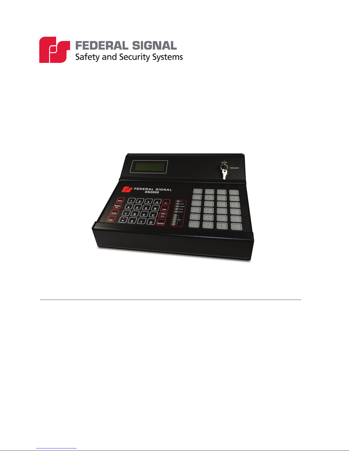
SS2000+ Encoder/Decoder
• Monitor Speaker to Monitor Incoming and Outgoing Trafc
• Powered from 12 to 30 Vdc, runs on standard 12 or 24 V backup power
Encoding
Program up to three codes under each activation input. There are sixty programmable
functions available. These codes can be Two-Tone, Single-Tone, EAS, DTMF, Federal
Signal Digital Codes (FSK) and activating the three Relay Outputs, or calling another
activation key. Send each activation code from one to three times.
Modes of Operation
You can set the SS2000+ in either standalone or computer mode. In either mode, any
poll requests or activation commands from Commander Software, updates the clock in
the SS2000+ to match the Commander Software time and date. In computer mode, all
reports, status, and activations are logged within the Commander Software.
The SS2000+ can also receive streamed audio and encode activations from Commander
Software or the SE3000 Software and transmit it out as audio.
Standalone Two-way Operation
Use the SS2000+ in standalone mode; that is, without a host computer application. When
in standalone mode, the SS2000+ does not function as a two-way radio modem for the
SE3000 Software or Commander Software applications.
In standalone mode, the SS2000+ acknowledges and prints incoming status reports and
alarms from remote devices. Acknowledgments conrm message receipt and keeps
remote devices from repeating transmissions.
The SS2000+ is congured with two lists of unit numbers: one for digital units and
one for DTMF units. Both types can exist in the same system. When a Report – All is
executed, the SS2000+ polls the active units in the digital list rst, logging each poll and
response. When complete, the SS2000+ polls the units in the DTMF list, logging each
poll and response. The DTMF status or alarm messages are converted to the same format
as the digital information. The incoming DTMF and digital messages are decoded and
displayed on the LCD.
Computer Mode Operation
The SS2000+ keypad and display are still operational in computer mode, but the
SS2000+ does not acknowledge incoming digital messages. It passes all messages to the
host computer application.
Automatic Logging
The SS2000+ displays all incoming and outgoing messages on its LCD display.
The SS2000+ prints all status reports on a line printer if the printer is enabled in the
conguration. If Com port 2 is congured for printer messages, the statuses and alarms
are sent there as well. The SS2000+ also logs each time it is powered up, all manual
encode activations, outgoing poll requests, and the results of each step in the self test
procedure.