FeelElec FY6800 Series User manual

FeelElec
FY6800 Series Fully Numerical Control
Dual Channel Function/Arbitrary Waveform Generator
User’s Manual
Rev1.1 April,2018

I
Guaranty and Declaration
Copyright
© 2017 FeelElec Technology Co. Ltd. All Rights Reserved.
Declaration
● FeelElec reserves the right to modify or change parts of or all the
specifications and pricing policies at company’s sole decision.
●Information in this publication replaces all previously corresponding material.
● FeelElec shall not be liable for losses caused by either incidental or
consequential in connection with the furnishing, use or performance of this
manual as well as any information contained.
●Any part of this document is forbidden to be copied or photocopied or
rearranged without prior written approval of FeelElec.
Contact Us
If you have any problem or requirement when using our products or this
manual, please contact FeelElec.
Website:www.feelelec.com

Contents
Guaranty and Declaration.............................................................................................I
Product Introduction..................................................................................................... 4
Quick Start ....................................................................................................................... 7
General Inspection.................................................................................................... 7
Front Panel Overview............................................................................................... 8
Back Panel Overview...............................................................................................11
Power On and Inspection....................................................................................... 12
User Interface .......................................................................................................... 13
Appearance and Dimensions...................................................................................... 15
Front Panel Operations .............................................................................................. 16
Waveform Output.................................................................................................. 16
Select Output Channel.......................................................................................................16
Select Waveform ................................................................................................................17
Set Frequency.....................................................................................................................18
Set Amplitude......................................................................................................................19
Set Offset.............................................................................................................................20
Set Duty Cycle (Square)....................................................................................................21
Set Phase............................................................................................................................22
Enable Output.....................................................................................................................23
Example:Output Sine Waveform...................................................................................24
Turn on burst function......................................................................................... 28
Frequency Meter/Counter................................................................................... 29
Enable the Counter............................................................................................................29
Set the Counter...................................................................................................................30
Sweep....................................................................................................................... 31
Sweep Object......................................................................................................................31
Sweep Start Position..........................................................................................................32
Sweep End Position...........................................................................................................33
Sweep Time.........................................................................................................................34
VCO (Voltage Control Output) Sweep.............................................................................34
Sweep Type.........................................................................................................................35
Enable Sweep Function.....................................................................................................36
System Configuration and Auxiliary Functions............................................ 37
Save and Load....................................................................................................................38
Configuration.......................................................................................................................39
Uplink ...................................................................................................................................40
Synchronization..................................................................................................................41
Troubleshooting........................................................................................................... 42
Technical Specification .............................................................................................. 43
Appendix ........................................................................................................................ 47

4FY6800 Series User’s Manual
Product Introduction
This manual applies to each model of FY6800series Function/Arbitrary
Waveform Signal Generator. The last three characters of the model indicate the
up limit output of Sine Wave (MHz). For example, the “60M”of the Model Number
“FY6800-60M”indicates the Sine wave maximum output frequency is up to
60MHz.
FY6800series Dual-channel Function / Arbitrary waveform generator is a set
of Function Signal Generator, Arbitrary Waveform Generator, Pulse Generator,
Analog / Digital modulator, VCO, Sweep, Counters and Frequency Meter and
other functions in a high Performance, cost-effective, multi-function signal
generator. Abundant shortcut keys and graphical user interface simplifies every
operation. Users do not have to spend a lot of time to learn and familiar with the
operation of the instrument, you can be skilled use. For education, research and
development, production, testing, maintenance and other industries to provide a
new choice.
The instrument adopt the Direct Digital Synthesizer (DDS) technology
and provide stable, precise, pure and low distortion signals. Surface mounting
technology improves interference immunity and operational life span. Can output
up to 97 groups of functions / arbitrary waveform, contains 33 groups of preset
waveforms and 64 groups of user-defined waveforms. Preset waveforms: Sine,
Square (Duty Cycle adjustable), Pulse (Pulse width and cycle time can be set
accurately), Triangle/Ramp, CMOS(0~10V), Four channels TTL, Exponential
Rise, Exponential Fall, Noise, ECG, DC etc.

FY6800 Series User’s Manual 5
Main Features:
Adopt the Direct Digital Synthesizer (DDS) technology and provide stable,
precise, pure and low distortion signals.
Desktop design with ABS plastic housing, AC 100 - 240V (AC) wide voltage
supply;
2.4 inch TFT Color LCD with 320×240 resolution, displaying parameters and
graphics of the two channels at the same time.
The instrument uses 14-bit high-speed D/A converter chip (5Vpp output
quantization error is less than 1mV), 250MSa/s sample rate, 14bits vertical
resolution.
Fully independent dual-channel output (equivalent to two independent signal
sources), able to work synchronously, and the phase difference can be
accurately adjusted;
Equipped with channel tracking function, when the tracking function is turned
on, all parameters of both channels can be updated according to the user's
configuration at the same time;
Two or more instruments can synchronize multiple instruments through the
SYNC port;
Up to 98 sets of function/arbitrary waveforms can be output, including 34 sets
of preset waveforms and 64 sets of user-defined waveforms. Preset
waveforms include: sine wave, square wave (duty ratio adjustable), triangle
wave, pulse wave (preset pulse width and frequency can be precisely set),
rise sawtooth wave, ramp sawtooth wave, staircase wave, trapezoidal pulse
wave, Sink Pulse, narrow pulse, noise, exponential rise, exponential drop,
electrocardiogram, Lorentz pulse, multiple audio waves, CMOS (0~10V),
four-channel TTL level and DC voltage;
Enable to store 64 arbitrary waveform data files, each one of waveform
storage depth 8192 points * 14bits;
High frequency accuracy: Frequency accuracy can reach 10-6 orders of
magnitude;
The frequency resolution is relatively high: the full-range frequency resolution
is 1uHz (0.000001Hz);
Amplitude resolution is higher:Amplitude resolution can be as low as 1mV
(0.001V);
With -10V~+10V DC bias function (<20MHz), resolution up to 1mV;

6FY6800 Series User’s Manual
The duty cycle of both channels can be adjusted independently, with an
accuracy of 0.01%;
The phase adjustment range of the two channels is 0~359.99°, and the
adjustment accuracy is 0.01°;
No range limit: The full range of frequency is not divided into gear switches,
program-controlled settings;
With digital signal output function, it can realize any CMOS level with 0~10V
amplitude;
Scanning function: It can scan the four properties of the signal: frequency,
amplitude, offset, and duty cycle. It has two scanning modes: linear scan and
logarithmic scan. The scan time can reach 999.99S. The start and end of the
scan can be set arbitrarily ;
Burst Output Function: There has Manual Trigger, internal CH2 Trigger, and
External Trigger for your options. It can output 1~1048575 pulse trains.
VCO function: Support VCO voltage control signal output function (such as
voltage controlled oscillator).
Various modulation types: AM, FM, PM, ASK, FSK and PSK modulations.
100M Frequency meter function: It can measure frequency, period, pulse
width and duty cycle. Max. frequency workable is 100MHz and Min.
frequency workable is 0.01 Hz.
Counter Function: It has 2 coupling measure modes including DC coupling
and AC coupling. This design can solve inaccuracy problem of AC coupling.
All parameters can be calibrated by internal procedures;
Equipped with powerful arbitrary waveform editing function, it can edit
arbitrary waveform on PC and download to instrument output waveform;
Powerful communication features that can be controlled using a PC. Open
communication protocol makes secondary development very simple;
Standard dual full functional channels which are equivalent to two
independent generators.
High reliability: Large-scale integrated circuit, surface mount technology, high
reliability, long service life;
Output short-circuit protection: All signal outputs can work under load
short-circuit conditions 60S or more;
Can choose our FYA2000S series or FPA1000 series power amplifier to
output 20W~100W signal in DC-10MHz width without any distortion.

FY6800 Series User’s Manual 7
Quick Start
General Inspection
Please follow the items below when you receive a new FY6800series
Function/Arbitrary Waveform Generator.
1.Inspect the shipping container for damage
Keep the damaged shipping container or cushioning material until the
contents of the shipment have been checked for completeness and the
instrument has passed both electrical and mechanical tests. The consigner or
carrier shall be liable for the damage to instrument resulting from shipment.
2.Inspect the instrument
In case of any damage, or defect, or failure, notify your FeelElec sales
representative.
3.Check the accessories
Please check the accessories according to the Appendix C ( packing lists). If
the accessories are incomplete or damaged, please contact your FeelElec sales
representative.

8FY6800 Series User’s Manual
Front Panel Overview
The front panel is divided into several function areas for easy operation.
Front Panel
Item
Function
Description
1
LCD
2.4 inch TFT(320×240)color LCD. Operation instruction please check
chapter “User Interface”.
2
Manu
Buttons
Manu buttons are matched with Manu displayed on the LCD. Press
corresponding button to activate submenu represented.
3
Function
Buttons Area
Waveform selection button:
—You can switch between sine, square wave, triangle
wave, and any type of arbitrary wave.
—Change the selected channel signal type.
Trigger and modulation function buttons
—Can set a specific number of pulse train output
function(BURS)
—Modulation mode can be set :ASK、FSK、PSK、AM、
FM、PM
Sine, square, sawtooth and arbitrary waveforms can be
scanned.
—Supports scanning of four parameters of frequency,
amplitude, offset, and duty cycle.
Supports two linear and logarithmic scanning methods.
Can switch to frequency meter and counter function,
measure frequency, period, duty cycle, positive pulse
width of external input signal
—Supports DC and AC signal input.

FY6800 Series User’s Manual 9
—Supports 1 s, 10 s and 100 s gate time switching.
—Dual channel output can work with frequency meter
measurement.
VCO function can be set
—Support VCO voltage control signal generator's
frequency, amplitude, offset, duty cycle and other
parameter output functions (such as
voltage-controlled oscillator).
Used to set auxiliary function parameters and system
parameters.
—Supports storage of 20 sets of parameters such as
frequency, amplitude, offset, and phase
—Support Chinese and English switching
—Support tone off/on
—Supports multi-machine cascading
—Supports master/slave switchover in cascaded state
—Supports dual-channel power-on default output state
setting
4
Arrows
Press Arrow buttons to select figure which you want to edit when setting
values of each parameter.
5
ADJ Knob
When using the knob to set parameters, you can increase (clockwise)
or decrease (counterclockwise) the value at the current cursor.
6
Power
Button
The power indicator will remain on when it is turned on.
When the signal generator is turned off, the indicator light will enter the
breathing lamp state and CH1 and CH2 will stop outputting (the output will
remain at 0 volts).
7
CH1 channel
output
connector
BNC connector, nominal output impedance 50Ω.
When channel CH1 is on (the CH1 button indicator lights up), the connector
outputs the waveform in the current configuration of CH1.
8
Channel
control, OK
button
It is used to control the output of the CH1 channel and can be
switched to the CH1 parameter setting interface in any
interface.
—Press this button, the CH1 light will turn on, and the CH1
output will turn on. At this point, the [CH1] connector outputs
the signal in the current configuration.
—Press this button again, the indicator light goes off, and at
this point, the CH1 output is turned off.
Confirm button
—When editing frequency parameters, press this key to
change the frequency unit.
—When scanning the interface, press this button to start/stop
scanning.

10 FY6800 Series User’s Manual
It is used to control the output of the CH1 channel and can be
switched to the CH1 parameter setting interface in any
interface.
—Press this button, the CH2 light will turn on, and the CH2
output will turn on. At this point, the [CH2] connector outputs
the signal in the current configuration.
—Press this button again, the indicator light goes off, and at
this point, the CH2 output is turned off.
9
CH2 channel
output
connector
BNC connector, nominal output impedance 50Ω.
When channel CH2 is on (the CH2 button indicator lights up), the connector
outputs the waveform in the current configuration of CH2.
10
AC coupling
measuring
terminal
BNC connector, input impedance 100Ω. For inputting signal of meter or
counter.

FY6800 Series User’s Manual 11
Back Panel Overview
The back panel of FY6800is as picture 1-2 below. 4 BNC terminals on the left
are DC coupling measuring terminals Trig/FSK/ASK/PSK IN, external sweep input
VCO IN, Synchronization output connector SYNC OUT, and Synchronization
input connector SYNC IN. Then follows TTL output terminal, USB terminal, power
switch and power input socket.
1. BNC connector
Trig/FSK/ASK/PSK IN: DC coupling measuring terminal and ASK/PSK/FSK
modulation trigger input terminal.
VCO IN: External signal sweep input terminal can realize voltage controlling
frequency, voltage controlling amplitude, voltage controlling offset, voltage
controlling duty cycle and so on. Frequency of external signal input should be
lower than 500 Hz.
SYNC OUT: Synchronization signal output terminal.
SYNC IN: Synchronization signal input terminal.
2. TTL signal output
Frequency of Port A is same with frequency of CH1 output. Frequency of Port B
is same with frequency of Port A but with reverse phase (180°). Frequency of
Port C is same with frequency of CH2. Frequency of Port D is same with Port C
but with reverse phase (180°).
3. USB Device interface
It’s for communication with PC (This is a USB-TTL serial port and driver is
needed). Can programming by host computer.
4.Power switch&Power input socket(voltage range AC100V-AC240V).
Warning
To avoid instrument damage, voltage of signal input from EXT.IN
CANNOT exceed ±20Vac+dc.Voltage of signal input from
Trig/FSK/ASK/PSK IN CANNOT exceed DC5V.
Note
To ensure the normal work, please use 100-240V AC power
supply.
12 FY6800 Series User’s Manual
Power On and Inspection
Connect to Power
Please connect the generator to AC power supply using the Power cable
supplied in the accessories. The power supply use 100-240V AC power. The
power of this instrument is less than 5W.
Power On
Turn on the power switch after the power cord is connected. The generator
will execute self-inspection. The LCD will show welcome interface after the
inspection is over. If the generator cannot work normally, please check the
Chapter “Troubleshooting”for solution.
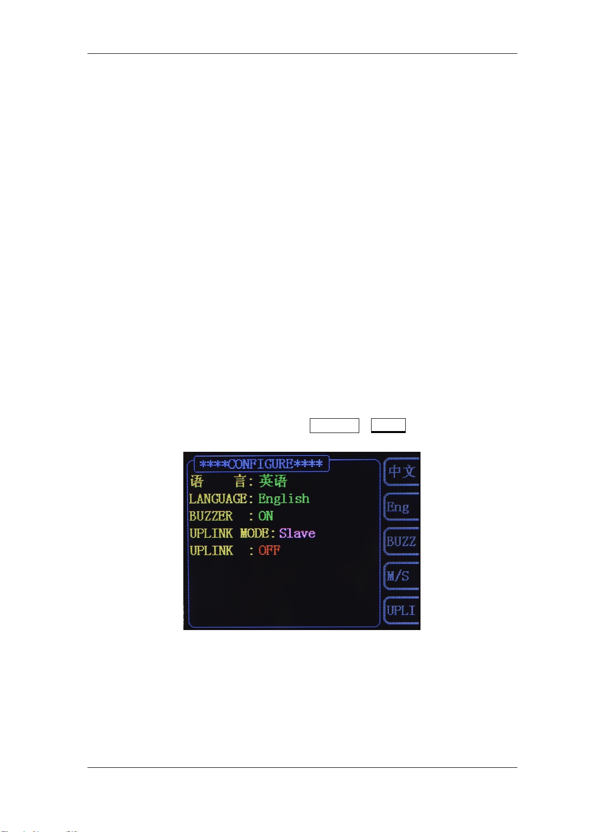
Set the System Language
FY6800series Function/Arbitrary Waveform Generator supports Chinese and
English system languages. You can press SYSTEM→CONF to switch the system
language.

FY6800 Series User’s Manual 13
User Interface
The user interface of FY6800provides four types of display modes: Dual
Channels Parameters (default), Single Channel Extension, Auxiliary Functions
and System Interface.
Dual Channels Parameters (default)
The upper half of LCD displays the channel selected currently and the
parameters can be set. Press CH1 or CH2 to change current channel selected.
1-4 User Interface (CH1 selected)
Item
Description
1
Current channel selected.
Display current channel selected for operation.
2
Current waveform selected.
Display the name of current waveform selected. For example,
“CH1=Sine”means current waveform selected of CH1 is
Sine Wave. It can be changed by press WAVE button.
Meanwhile, waveform can be changed quickly by rotating
ADJ Knob when waveform switch function is activated.
3
Output status of current channel.
Display On/Off status of current channel. It can be switched
by Press CH1 or CH2.
4
Waveform
Display diagram of current waveform(Including Arbitrary).
Yellow indicates CH1 and blue indicates CH2.
5
Manu Bar
Display current operable options .

14 FY6800 Series User’s Manual
6
Frequency
Display frequency value of current channel. Press FREQ
button to highlight it and use ADJ Knob and Arrows to change
the value.
7
Amplitude
Display amplitude value of current channel. Press AMPL
button to highlight it and use ADJ Knob and Arrows to change
the value.
8
Offset
Display DC Offset value of current channel. Press OFFS
button to highlight it and use ADJ Knob andArrows to change
the value.
9
Duty Cycle
Display Duty Cycle value of current channel. Press DUTY
button to highlight it and use ADJ Knob andArrows to change
the value.
10
Phase
Display Phase value of current channel. Press PHAS to
highlight it and use ADJ Knob and Arrows to change the
value.
11
Parameters of the channel unselected.
Display parameters of the channel unselected including
frequency, amplitude, offset, phase, duty cycle and output
status. These Parameters cannot be changed directly in this
interface. If you need to change them, Please switch the
channel to be selected.

FY6800 Series User’s Manual 15
Appearance and Dimensions

16 FY6800 Series User’s Manual
Front Panel Operations
Waveform Output
FY6800series can output waveforms (Sine, Square, Triangle/Ramp, Pulse
and Noise etc.) from one of the channels separately or from the two channels at
the same time. At start-up, the dual channels are configured to output a sine
waveform with 10kHz frequency and 5Vpp amplitude by default. Two channels
use default setting saved at Position 1 when power on. Users can configure the
instrument to output various waveforms.
Select Output Channel
CH1 and CH2 buttons are used to change current channel selected. At
start-up, CH1 is displayed on the top with yellow color and CH2 is displayed on
the bottom with blue color. Press CH1 or CH2 to select channel needed. When
selecting CH2 as output channel, CH2 parameters displays on the top for
configuration.
KEY POINT:
CH1 and CH2 can not be selected at the same time. Users can first select
CH1 and then select CH2 after configuring the waveform and parameters of
CH1. If you need to change the parameters of two channel at same time,
please refer to Chapter “Synchronization”.

FY6800 Series User’s Manual 17
Select Waveform
FY6800 can output Function/Arbitrary Waveform including:
Sine
Square
Triangle/Ramp
Rise Sawtooth
Fall Sawtooth
Lorenz Pulse
Multitone
Noise
Electrocardiogram (ECG)
Trapezoidal Pulse
Sinc Pulse
Narrow Pulse
Gauss White Noise
Step Triangle
Positive Step
Inverse Step
Positive Exponent
Inverse Exponent
Positive Falling Exponent
Inverse Falling Exponent
Positive Logarithm
Inverse Logarithm
Positive Falling Logarithm
Inverse Falling Logarithm
Linear FM
AM
FM
Positive Half Wave
Negative Half Wave
Positive Half Wave
Rectification
Negative Half Wave
Rectification
User-defined waveform
Press WAVE to change waveform selected. Or rotate ADJ Knob under waveform
switching status to change waveform. The waveform diagram displays on the
screen. Pressing the knob can change to arbitrary waveform directly when
choosing waveform. At start-up Sine is selected by default. (Users can also
configure start-up waveform. Please check Chapter “Save and Load”.
Waveforms
Sine
Square
Triangle
Sawtooth
Arbitrary
Function Name
SINE
SQUR
TRGL
Ramp
Arb
Parameters
Frequency
√
√
√
√
√
Amplitude
√
√
√
√
√
Offset
√
√
√
√
√
Phase
√
√
√
√
√
Duty Cycle
√
Note: Arbitrary waveforms can be edited and downloaded from PC software
provided by FeelElec. The relevant software and driver can be downloaded from
our website: www.feelelec.com .

18 FY6800 Series User’s Manual
Set Frequency
Frequency is one of the most important parameters of waveforms. For
different instrument models and waveforms, the setting ranges of frequency are
different. For detailed information, please refer to “Frequency” in
“Specifications”. The default frequency is 10kHz.
Press FREQ button to highlight value of Frequency. Then useArrow
buttons and ADJ Knob to set the value. Press Arrows button to move the cursor
and rotate ADJ Knob to set the value.
Under setting frequency status, pressADJ Knob to change frequency units
among MHz, KHz, Hz, mHz, μHz.

FY6800 Series User’s Manual 19
Set Amplitude
The amplitude setting range is limited by the “Attenuation” and “Frequency”
settings. Please refer to “Output Characteristics” in “Specifications”. The
default value is 5Vpp.
Press AMPL button to highlight amplitude value. Then use Arrows button
and ADJ Knob to set the value. Press Arrows button to move the cursor and
rotate ADJ Knob to set the value.
Key Points:
1.What’s the difference of amplitude in Vpp and the corresponding value in
Vrms?
Answer:
Vpp is the unit for signal peak-peak value and Vrms is the unit for signal effective value.
The default unit is Vpp.
Note:
For different waveforms, the relation between Vpp and Vrms is different. The
relation of the two units is as shown in the figure below (take sine waveform as
an example).
According to the figure above, the conversion relation between Vpp and Vrms
fulfills the following equation:
Vpp = 2
2
Vrms
For example, if the current amplitude is 5Vpp, For sine waveform, the
converted value is 1.768Vrms.

20 FY6800 Series User’s Manual
Set Offset
Press OFFS button to highlight offset value. Then use Arrows button and
ADJ Knob to set the value. Press Arrows button to move the cursor and rotate
ADJ Knob to set the value.
The offset accuracy is 1mV. i.e. 0.001V.
When frequency output is lower than 20MHz, the offset can be adjusted
during -10V~+10V.
When frequency output is higher than 20MHz, the offset can be adjusted
during -2.5V~+2.5V.
Table of contents


