bloom 25 GPM Installation manual
BLOOM 1.5 INSTALLATION AND STARTUP
GUIDE
REFER TO OPERATING MANUAL FOR IMPORTANT SAFETY
INFORMATION

- 2 -
PAGE INTENTIONALLY LEFT BLANK

- 3 -
CONTENTS
GENERAL INFORMATION .........................................................................................................4
LOCATION REQUIREMENTS.....................................................................................................4
PARTS AND ACCESSORIES......................................................................................................5
INSTALLATION GUIDELINES.....................................................................................................6
Installation Parts and Materials..................................................................................................6
Pipe Assembly..............................................................................................................................6
Gas Connection ..........................................................................................................................7
Flooded Suction Installation ......................................................................................................7
Suction Lift Installation.................................................................................................................8
Table 4. Recommended Suction and Discharge Pipe. .................................................................9
Frame Dimensions and Components Descriptions.......................................................................9
Suction Piping Installation..........................................................................................................10
Discharge Piping Installation......................................................................................................11
CIP Valve Installation (Optional) ................................................................................................12
Connect Power to Control Box. ..............................................................................................12
QUICK STARTUP GUIDELINES................................................................................................13
Flooded Suction Applications: Pump Priming Instruction............................................................13
Suction Lift Applications: Pump Priming Instructions...........................................................15
Suction and Discharge Operation............................................................................................17
Operating Parameter Ranges...................................................................................................17

- 4 -
PAGE INTENTIONALLY LEFT BLANK

- 4 -
GENERAL INFORMATION
Read instructions thoroughly prior to assembly and installation.
All Bloom products are factory adjusted for optimal nanobubble production. Do not
adjust factory setpoints.
LOCATION REQUIREMENTS
Carefully select the BLOOM installation location based on the requirements specified in this
section. Locate and secure the BLOOM on a concrete pad or other firm, level surface that is
at least 44 in long x 23 inches wide. Maintain a clearance of at least 30 inches on all sides to
allow access for servicing and maintenance to the front and back of the BLOOM. Select a
sheltered, (weatherproof), well-ventilated area that is protected from excess moisture (i.e.,
rain, splashing, washdown water, etc.), dust and flooding. Use the schematic shown in
Figure 1 for mounting hole placement.
Figure 1. Plan view of BLOOM frame showing mounting hole placement.
The BLOOM power, suction and discharge pipe requirements are summarized in Table 1 and
Table 4 respectively.
Failure to install BLOOM within the limits specified in Tables 1 and 4 may void the
system warranty and result in poor nanobubbles production and pump cavitation.
- 5 -
Table 1. Power Requirements
PARTS AND ACCESSORIES
The parts shown in Table 2 are offered as accessories available for purchase with all BLOOM
models.
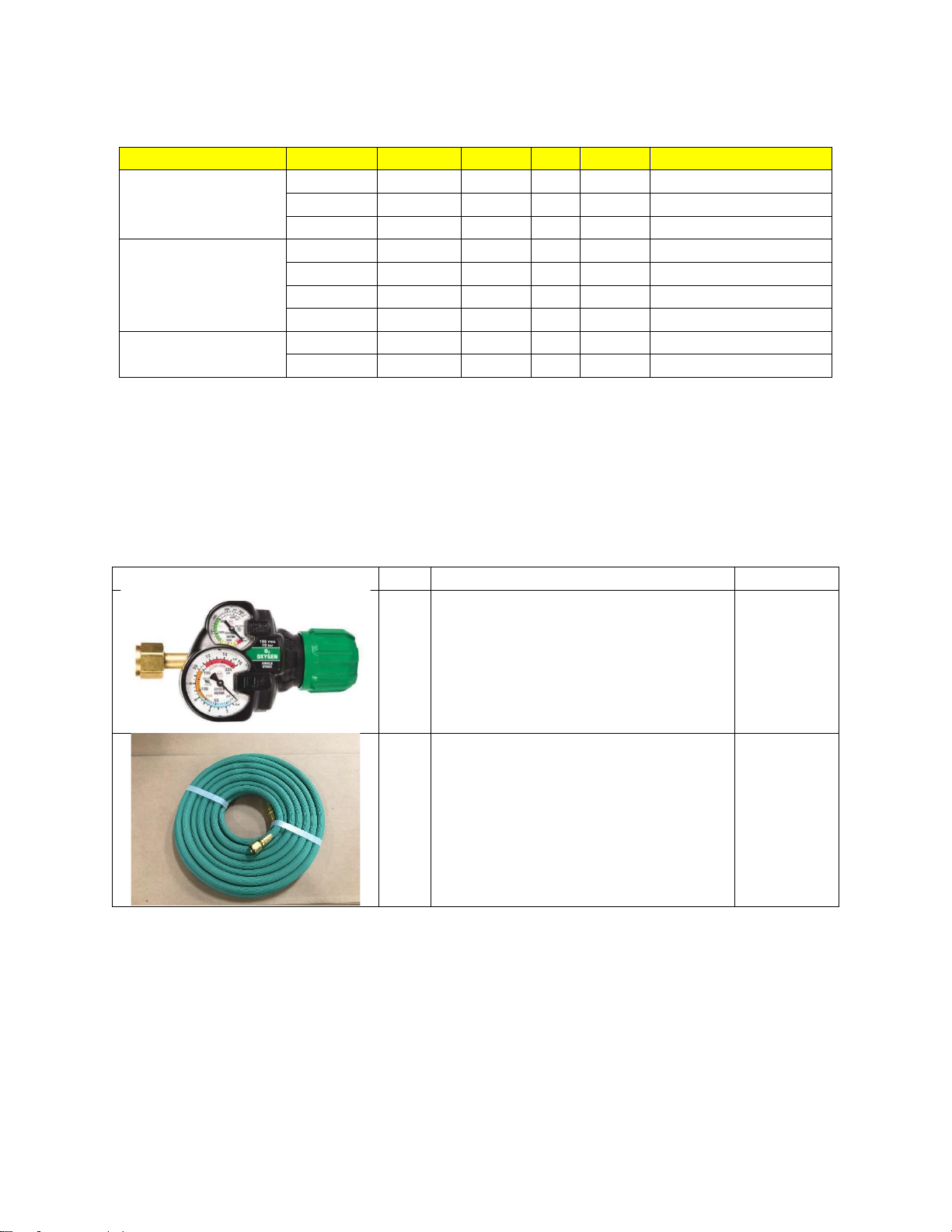
Table 2. High Pressure Oxygen Regulator Kit Parts List (P/N:99K0-001)
Image
QTY
Part Description
P/N
1
Regulator Oxygen
99J0-050
1
Hose, Welding Gas, Grade R, Green.
99C0-084
Unit
Version
Voltage
Phase
Hz
Amps
Pump Manufacturer
BLOOM 25 GPM
US
115
1
60
10.2
Pentair
US
230
1
60
6.0
Pentair
EU
230
1
50
6.9
Pentair
BLOOM 50 GPM
US
115
1
60
12.7
Pentair
US
230
1
60
6.8
Pentair
EU
230
1
50
16.9
Pentair
US
115
1
60
12.7
DAB
BLOOM 150 GPM
US
230
1
60
15.8
Pentair
EU
230
1
50
16.9
Pentair
- 6 -
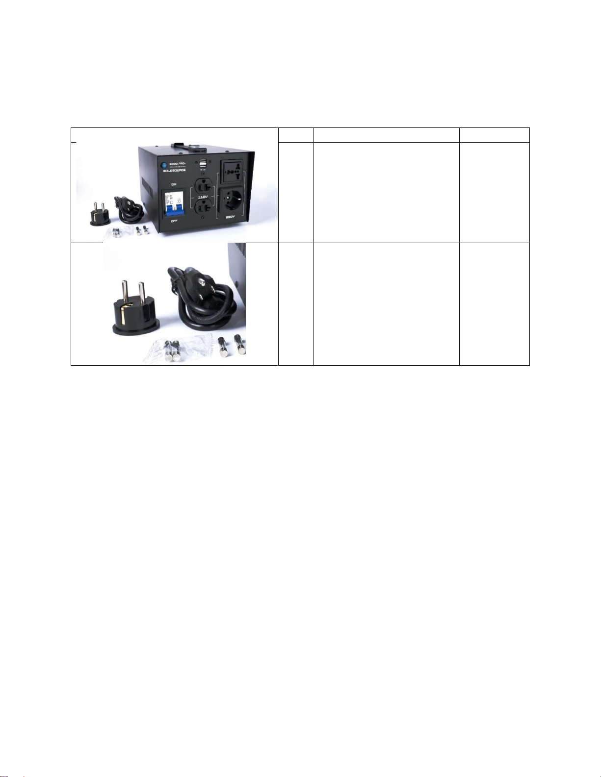
NOTE: The parts shown in Table 3 are offered as accessories to the DAB pump and are only
available for purchase with the US BLOOM 50.
Table 3. Power Converter
Image
QTY
Part Description
P/N
1
Step Up- Down Transformer
99E0-235
1
Adapter
99E0-234
INSTALLATION GUIDELINES
The site conditions unique to each irrigation reservoir, irrigation room, or commercial
greenhouse project, etc., should be carefully considered when identifying the BLOOM
installation location. Refer to the Location Requirements section for addition details.
The following guidelines are recommendations for tanks with intake structure submergence.
depths less than15 ft (4.5m).
Upon delivery, unscrew the shipping screws to remove the BLOOM unit from the shipping crate.
Inspect the BLOOM for any damage or loose parts that may have occurred during transport.
Hand tightens any loose parts, make sure don’t over tight.
Installation Parts and Materials
The parts and materials required to install the BLOOM include:
•3/8 in wrench (US models) or 14mm wrench (EU models).
•7/8 in wrench (US models) or 34mm wrench (EU models). Wrench required to install the
regulator kit.
Follow
Pipe Assembly
- 7 -
Use only Schedule 40 or Schedule 80 polyvinyl chloride (PVC) pipe and fittings. Use only PVC
cement formulated for wet condition and fast installation to ensure connection between PVC
pipe to PVC fittings. Follow PVC cement manufacturer’s recommendations on cure time before
wet testing the system. Do not use black, ABS piping or mix ABS pipe with PVC pipe or fittings.
All PVC pipe connections must be airtight and leakproof. Failure to provide airtight suction
pipe connections may negatively impact nanobubble generator performance. Large
bubbles visible at the pump strainer basket are an indication of suction pipe leaks. Difficulty with
pump priming may also be the result of suction pipe leaks.
Gas Connection
For BLOOM models without onboard gas generation, connect a high pressure rated oxygen gas
line to the standard CGA-022 fitting connection. Adjust the oxygen gas regulator on the gas
supply to 100 –120 PSIG.
DO NOT EXCEED 140 PSIG SUPPLY GAS PRESSURE. Excessive pressure may
void warranty and compromise gas seals resulting in a sudden drop in backpressure.
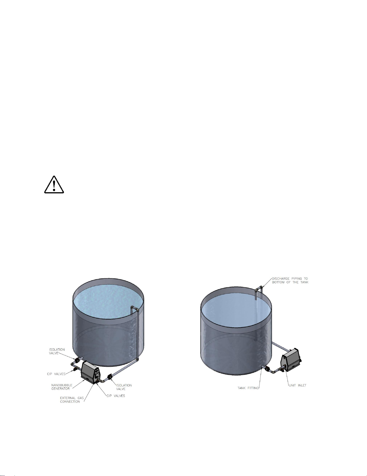
Flooded Suction Installation
Refer to Figures 2 and 3 to determine whether the installation has a flooded suction pipe. A
flooded suction exists when the pipe between the tank and the BLOOM pump completely fills
with water when the pump is off and isolation valves are open (i.e., when the tank water
surface level is above the suction intake and the BLOOM pump). Refer to Figure 7 for BLOOM
enclosure dimensions and suction and discharge fitting locations.
Figure 2. Isometric View a Flooded Suction BLOOM installation.

- 8 -
Figure 3. Plan View of BLOOM Discharge Pipe Orientation in a Tank.
Suction Lift Installation.
Refer to Figures 5 to determine whether the installation has a suction lift pipe. A
suction lift exists when the source of liquid is located below the BLOOM centerline. The suction
pipe leading to the pump and the pump must primed to lift liquid from the tank to the BLOOM.
Figure 4. Isometric View Suction Lift Installation
Do not run the pump dry. Impeller may melt and seize, and the pump will stop running.
See Figure 3 for plan view of BLOOM suction lift pipe orientation in a Tank.

- 9 -
Table 4. Recommended Suction and Discharge Pipe.
UNIT
MAIN PIPE
TANK FITTING
ISO VALVE
CIP VALVE
UNIT INLET
BALL CHECK VALVE
25 BLOOM
2"
2"
2"
1"
2"
2"
50 BLOOM
2"
2"
2"
1"
2"
2"
150 BLOOM
3"
3"
3"
1 - 1/2"
2"
3"
Piping connections for all sizes of BLOOM are provided below. Verify the type of pump provided
with your BLOOM before beginning installation. These materials are not included with a
purchase of a BLOOM, but can be found at most hardware stores.
Frame Dimensions and Components Descriptions.
Figure 5 shows the overall BLOOM frame dimensions and the location of the suction and
discharge ports of the pump in metric and imperial units.
Figure 8 shows the major components of the BLOOM.
Figure 7. BLOOM with suction and discharge connection locations
Figure 5. BLOOM with suction and discharge connection locations

- 10 -
Figure 6. Isometric views of BLOOM with Components Description
Suction Piping Installation
Install piping as close to the water body as possible. Keep pipe length as short as possible
and configure suction piping in a manner that minimizes the number of fittings (bends) and
valves.
Run a length of straight horizontal piping to the suction side of the pump. The length of this pipe
should a minimum of five (5) pipe diameters. Example: If system is to be plumbed with 90mm
(3”) diameter PVC pipe, then a straight section of pipe 38cm (2”) long should be used immediate
to the suction side of the pump.
Locate and install the suction pipe following the recommendations detailed in Figures 3 and 4
for a flooded suction installation. Use fittings as necessary to route the suction piping from the
BLOOM to the tank.
Water flows through a check valve in only one direction as indicated by the flow arrow on the
check valve. The check valve is normally in the closed position and opens in response to the
pump drawing suction from the tank. Ensure the check valve is installed with the flow arrow in
the direction of suction flow so as not to restrict flow from the waterbody to the pump. Check
valve is needed in the flooded lift installations only.

- 11 -
For installations where debris is approximately greater than 1/8” (3 mm) in size are present in
water, install a screen on the intake of the suction pipe to ensure that large solids do not pass
through the BLOOM. Verify that the intake screen is rated for the flow liquid capacity of your
BLOOM and does not restrict the generator’s design liquid flow rate.
Discharge Piping Installation
Locate and install the discharge pipe following the recommendations detailed in Figure 3 for the
installation. Use pipe fittings as necessary to route the discharge piping from the BLOOM
unit to the tank wall. The discharge pipe can be routed over the top of or through the tank wall.
Install discharge pipe at the maximum water submergence depth and connect a 90 –
degree elbow to the end. Angle the discharge tangential to the tank to create a circular current
to assist with mixing.
Figure 7. –BLOOM Discharge Pipe at Maximum Water Submergence Depth.
- 12 -
CIP Valve Installation (Optional)
Two optional shut-off valves can be used to isolate the BLOOM from the rest of the system
for Clean in Place maintenance. See Table 4 for CIP valve sizes recommendations.
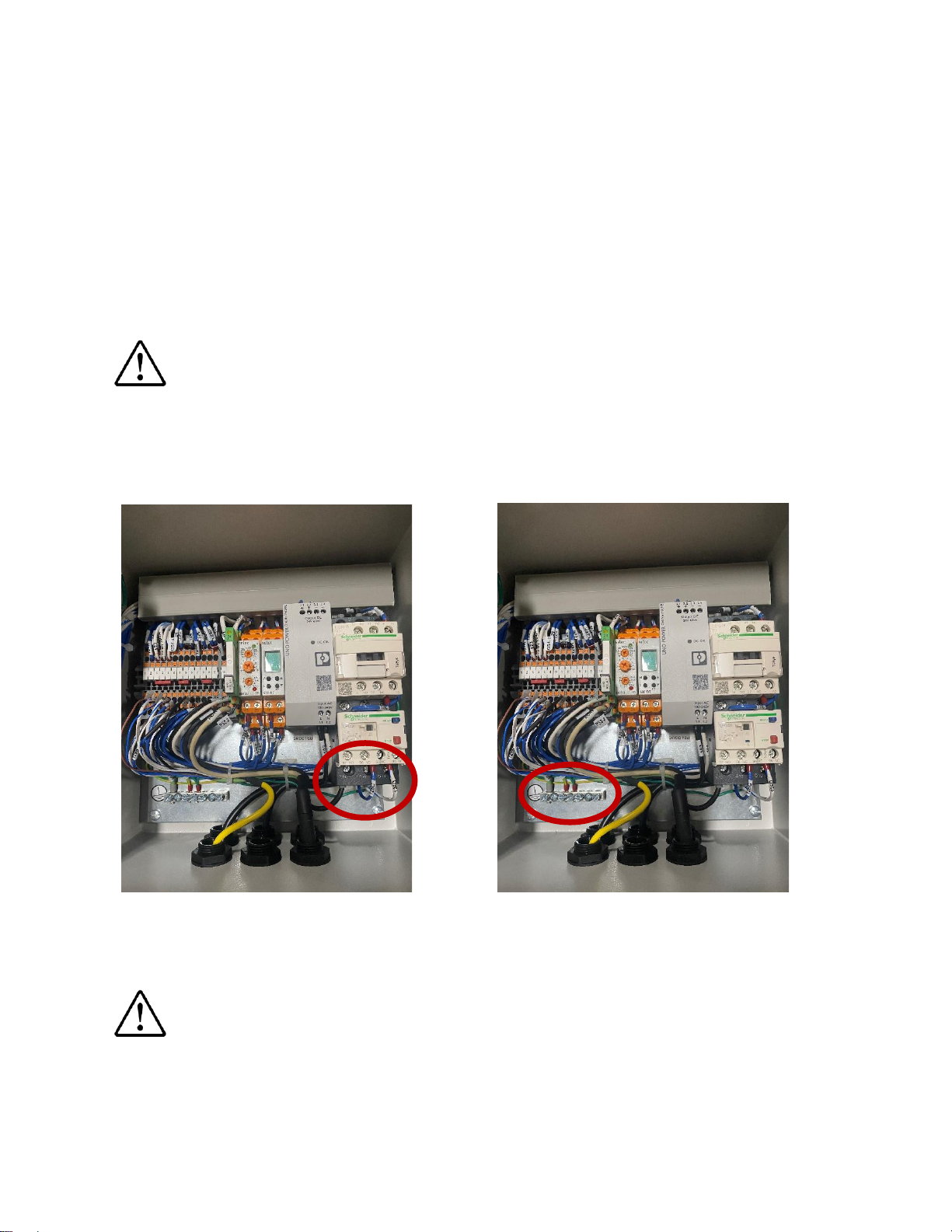
Connect Power to Control Box.
WARNING: Before connecting power, verify the voltage, phase and amps
requirements of your BLOOM. See purchase order for unit details.
All BLOOMS are single-phase model, there will be two wires coming out of the overload relay,
as shown in the red circle photo 1. Photo 2 shows the ground connection.
Photo 1. Output Terminal Connections on Photo 2. Ground
Overload Relay Wired for a Single Phase.
WARNING: Ensure that the ground wire from the power cable is connected to the
grounding bar inside the enclosure.

- 13 -
QUICK STARTUP GUIDELINES
WARNING: Refer to the operating manual for important safety and startup information.
When all piping is installed and pipe glue cure time has been met, connect electricity in
accordance with applicable Local Electrical Code and ordinances. The use of an
extension cord is hazardous and should be avoided.
Flooded Suction Applications: Pump Priming Instruction
Step 1. Open the intake and discharge valves to flood piping.
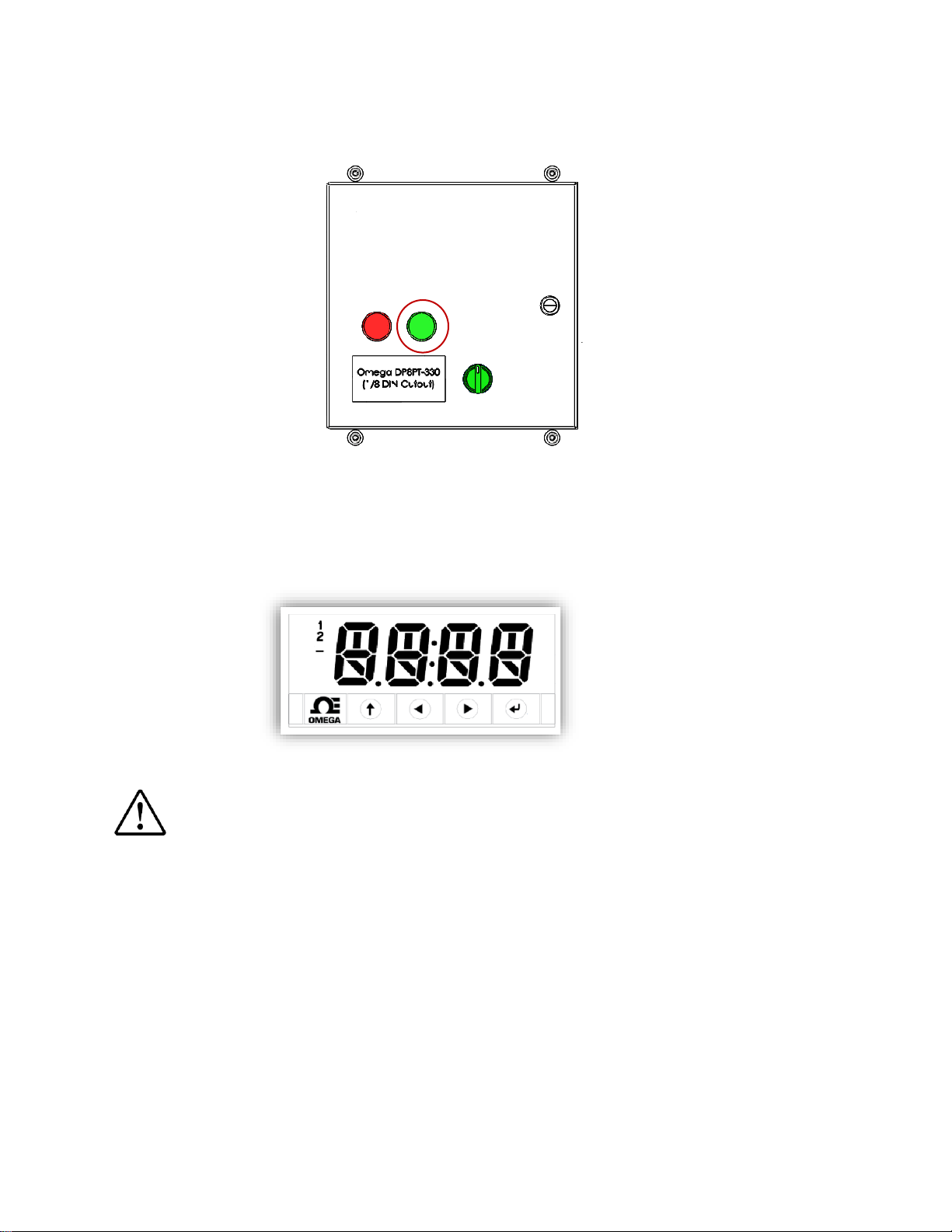
Step 2. Turn on the main power by using the green selector switch.
Intake and discharge valves.
- 14 -
Step 3. Press the green bottom to select “AUTO” position.
Step 4. The four button / LED display interface allows continuous monitoring of
sensor values, as well as for quick changes to LOW and HIGH setpoints.
Refer to the operating manual for more details in how to operate controller.
WARNING: Do not use isolation valves to throttle the pump. This may cause
loss of prime, excessive temperature, and damage of the pump, voiding
warranty.
Step 5. Check piping for visible leaks. If your BLOOM pump is equipped with a pump
strainer, verify through the clear window in the strainer lid that there are no bubbles
entering in through the liquid suction stream.
A large air pocket or large bubbles should not be visible in the strainer basket. If large
bubbles or an air pocket is visible in the strainer basket there is a suction pipe leak.
Turn OFF BLOOM and check suction pipe for leaks and ensure all pipe connections
are airtight.
Refer to the BLOOM Manual to configure the operational mode of the BLOOM.

- 15 -
Suction Lift Applications: Pump Priming Instructions
Step 1. Open the intake and discharge valves to flood piping.
Step 2. Turn on the main power by using the green selector switch.
Intake and discharge valves.

- 16 -
Step 3. Press the green bottom to select “AUTO” position.
Step 4. The four button / LED display interface allows continuous monitoring of
sensor values, as well as for quick changes to LOW and HIGH setpoints.
Refer to the operating manual for more details in how to operate controller.
WARNING: Do not use isolation valves to throttle the pump. This may cause
loss of prime, excessive temperature, and damage of the pump, voiding
warranty.
Step 5. Check piping for visible leaks. If your BLOOM pump is equipped with a pump
strainer, verify through the clear window in the strainer lid that there are no bubbles
entering in through the liquid suction stream.
A large air pocket or large bubbles should not be visible in the strainer basket. If large
bubbles or an air pocket is visible in the strainer basket there is a suction pipe leak.
Turn OFF BLOOM and check suction pipe for leaks and ensure all pipe connections
are airtight.
Refer to the BLOOM Manual to configure the operational mode of the BLOOM.

- 17 -
Suction and Discharge Operation
Turn the BLOOM on and observe the suction and discharge locations in the waterbody.
The intake should not create a vortex at the surface. If a vortex is visible, the suction
intake is not properly submerged. Verify that the suction is at least 2 ft beneath the
minimum water level. The bubble pattern visible at the surface of the water above the
discharge should consist primarily of small bubbles, roughly the size of a pea or smaller.
If bubbles are consistently larger than the size of a small pea, contact a Moleaer technical
service representative at (424) 558-3567.
Operating Parameter Ranges
Normal operating ranges for the BLOOM units are shown in Table 5.
Table 5. BLOOM Normal Operating Ranges
Parameter
BLOOM 25
BLOOM 50
BLOOM 150
Gas Pressure (Gauge)
40-120 psig
40-120 psig
40-120 psig
Liquid Pressure (Gauge)
10-20 psig
10-20 psig
10-20 psig
Gas Flow Rate (Standard)
(US) & (EU) (Rotameter)
0-2.5 CFH
0-5 CFH
0-10 CFH
If the BLOOM unit is consistently operating outside of the ranges shown in Table 4,
contact a Moleaer technical service representative at (424) 558-3567.
This manual suits for next models
2
Table of contents
Other bloom Test Equipment manuals


Popular Test Equipment manuals by other brands

JDS Uniphase
JDS Uniphase Network Device JDSU brochure

Ametek Land
Ametek Land Landcal P1600B2 user guide

Keysight
Keysight 8516A Operating and service manual

Proceq
Proceq Pundit PL-200 manual

TEXIO
TEXIO DCS-1000B SERIES instruction manual

BluePoint MEDICAL
BluePoint MEDICAL AlcoTrue E operating instructions


