Feider Machines FCD37KW-1 User manual

ORIGIINAL INSTRUCTIONS
1
INSTRUCTION MANUAL
Diesel heater 37KW
FCD37KW-1
BUILDER SAS
ZI-32, rue Aristide Bergès, 31270 Cugnaux, France
MADE IN PRC
IMPORTANT:
Read and understand all of the directions in this manual before assembling, starting, or servicing the
heater. Improper use of this heater can cause serious injury.Keep this manual for future reference, not
suitable for use wood floors or other combustible materials. Retain this manual for future reference.

ORIGIINAL INSTRUCTIONS
2
Table of Contents
1. Safety information...........................................................................................................3
2. Features.............................................. ................................................................................5
3. Specification....................................... ................................................................................6
4. Unpacking........................................... ................................................................................6
5. Assembly.............................................................................................................................7
6. Operation............................................ ................................................................................8
7. Ventilation............................................................................................................................9
8. Long Tern Storage............................. ...............................................................................11
9. Maintenance....................................... ...............................................................................12
10. Wiring Diagrams.............................. ...............................................................................16
11. Troubleshooting...............................................................................................................16
12. DECLARATION OF CONFORMITY.............................................................................18
13. Warranty.......................................................................................................................19
14. PRODUCT FAILURE ...................................................................................................20
15. WARRANTY EXCLUSIONS.........................................................................................21
ORIGIINAL INSTRUCTIONS
3
1. Safety Information
NEVER LEAVE HEATER UNATTENDED WHILE BURNING OR WHILE COONECTED TO A
POWER SOURCE!
Indicates an imminently hazardous.
Situation which, if not avoided, WILL result in death or serious injury.
Indicates an potentially hazardous.
situation which, if not avoided, COULD result in death or serious injury.
Indicates an potentially hazardous.
Situation which, if not avoided, MAY result in minor or moderate injury.
GENERAL HAZARD WARNING:
Be sure to comply with the instructions and warnings provided with this heater, or death, serious
bodily injury and property loss, damage from the hazards of fire, explosion, burn, asphyxiation, and
carbon monoxide poisoning can result.
Only persons who can follow and understand these instructions should use or service this heater.
If you need heater information such as an instruction manual, labels etc; contact the dealer or
manufacturer.
NOT FOR USE IN NON-ADEQUATELY VENTEILED ENCLOSED SPACES.
Fire,burn, inhalation and explosion hazard. Keep combustibles, such as building materials, paper
or cardboard, a safe distance away from the heater as recommended by these instructions. Never
use the heater in spaces which contain products such as gasoline, solvents, paint thinners, dust
particles, volatile or airborne combustibles, or any unknown chemicals. This is an unvented
portable heater.It uses air (oxygen) from the area in which it is used. Adequate combustion and
ventilation air must be provided.
Do not operate this heater until you have read, and thoroughly understand these safety and
operating instruction. Failure to comply with the precautions and instructions provided with this
heater can result in death, serious bodily injury, property loss or damage from the hazards of fire,
soot production, explosion, burns, asphyxiation or carbon monoxide poisoning. Only persons who
can read and understand these instructions should use or service this heater. Not for use in home
or recreational vehicles.
Electrical Safety It is the responsibility of the owner to check this electrical product
before use to ensure it is safe. You must inspect power cables , plugs, sockets etc for signs of wear
or damage. You must ensure this risk of electric shock is minimized by the installation of
appropriate safety devices. A residual current circuit breaker (RCCB) should be incorporated in the
main distribution board. We also recommend a residual current device is used (RCD). An RCD is
Particularly important for mobile devices that are connected to a supply without an RCCB. Any fault

ORIGIINAL INSTRUCTIONS
4
rectification or electrical work including the connection of a plug must be carried out by a qualified
electrician.
You must also comply with electrical safety requirements including the Electricity at Work Act 1989
which requires portable electrical appliances used on business premises be PAT tested annually.
The Health & Safety at work Act 1974 places responsibility for safe condition of electrical
appliances upon owners. Power cables and plugs should always be regularly inspected for safety.
If in doubt about electrical safety, you must consult a qualified electrician.
This is a Diesel (1-K Kerosene) directed-fire forced air heater. It is primarily intended for use for
temporary heating of buildings under construction, alteration or repair. Directed-fired means that
all of the combustion products of the heater enter the heated space. This appliance is rated at
98% combustion efficiency, but does produce small amounts of carbon monoxide. Carbon
monoxide is toxic.
Carbon Monoxide poisoning may lead to death!
Humans can tolerate small amounts of carbon monoxide and precautions should be taken to
provide proper ventilation. Failure to provide proper ventilation according to this manual can
result in death. Early signs of carbon monoxide poisoning resemble the flu.
Symptoms of improper ventilation are:
* Headache * dizziness * burning of the nose and eyes
* nausea * dry mouth * sore throat *
For optimal performance of this heater, it is strongly suggested that 1-K kerosene be used, 1-K
kerosene has been refined to virtually eliminate contaminants, such as sulfur. Which can cause
a rotten egg odor during the operation of the heater, However, #1 or #2 fuel oil - diesel may also
be used if 1-K kerosene is not available. Be advised that these fuels do not burn as clean as 1-K
kerosene, and care should be taken to provide more fresh air ventilation to accommodate any
added contaminants that may be added to the heated space. Use of #1 or #2 fuel oil may result
in more periodic maintenance
Risk of indoor air pollution!
-Use this heater only in well ventilated areas ! Provide at least a three square foot (2800 sq cm)
opening of outside air for every 29KW/hr ) of heater rating
-Carbon Monoxide Poisoning. Early signs of carbon monoxide poisoning resemble flu-like
symptoms such as headaches, dizziness, and/or nausea. If you have these symptoms, your
heater may not be working properly
-Get fresh air at once ! Have the heater serviced. Some people are more affected by carbon
monoxide than others. These include pregnant women, those with heart or lung problems,
anemia or those under the influence of alcohol, or at high altitudes.
Risk of burns / fire / explosion!
-NEVER use fuels such as gasoline, benzene paint thinners, or other oil compounds in this
heater(RISK OF FIRE OR EXPLOSION)
-NEVER refill the heater’s fuel thank while heater is operating or still hot. This heater is
EXTREMELY HOT While in operating.
-Keep all combustible materials away from this heater.
-NEVER block air inlet or air outlet of the heater.
-NEVER use duct work in front or at rear of heater.
DANGER
ORIGIINAL INSTRUCTIONS
5
-NEVER move or handle heater while still hot.
-NEVER transport heater with fuel in its tank.
-If equipped with a thermostat, the heater may start at any time.
-ALWAYS locate heater on a stable and level surface.
-ALWAYS keep children and animals away from heater.
-Bulk fuel storage should be a minimum of 762cm from heaters, torches, portable generators or
other sources of ignition. All fuel storage should be in accordance with federal, state, or local
authorities have jurisdiction.
-NEVER use this heater in living or sleeping areas.
-NEVER use this heater where flammable vapors may be present.
-Use only the electrical power (Voltage and frequency) specified on the model plate of the heater.
Use only a local correct plug,grounded outlet and extension cord.
-ALWAYS install the heater so that it is not directly exposed to water spray, rain, dripping water, or
wind.
-ALWAYS unplug the heater when not in use.
Minimum clearance from combustibles:
Top 125cm
Side 125cm
Front 250cm
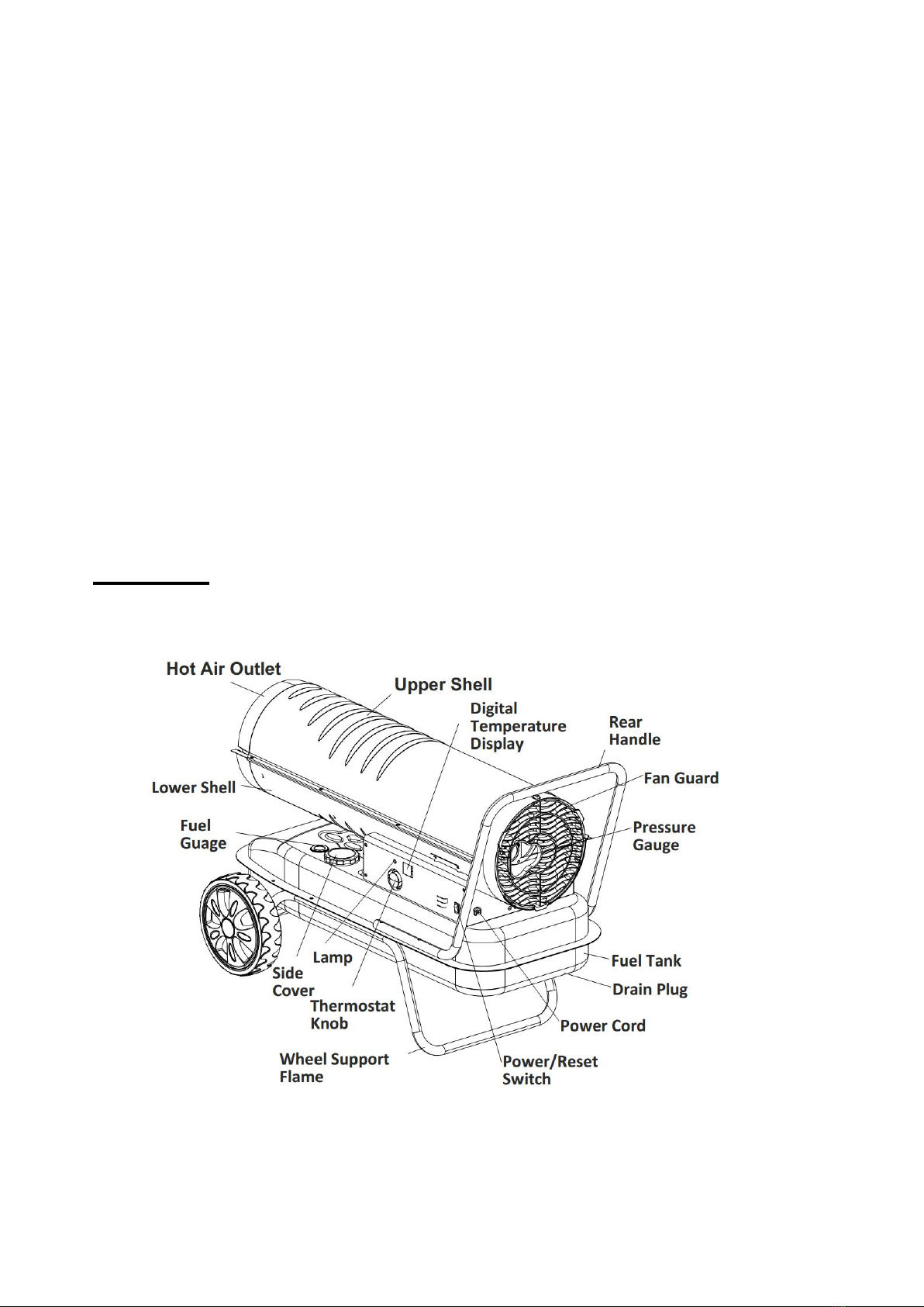
2. Features
Fig.1

ORIGIINAL INSTRUCTIONS
6
3. Specifications
Model
FCD37KW-1
Heat Output (KW)
37
Fuel Consumption (L/Hr)
3.6
Fuel Tank
Capacity (L)
38
Pump Pressure
(Kpa/Psi)
38.0/5.5
Power Supply
(V/Hz/A)
220-240/50/5
Phase
single
Size
(L*W*H CM)
105*54.2
*62
Net Weight (Kgs)
23.1
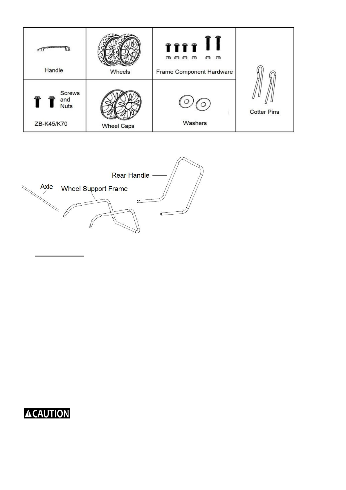
Fig.2
4. Unpacking
Remove the heater and all of the packing materials from the shipping
carton.Check the chart below to be sure that you have all of the parts
NOTE:Save the box and packing materials for future storage.
Wheel support frame
YES
Wheel ( 2 pieces)
YES
Rear Handle
YES
Axle
YES
Top Handle
NO
Screws & Nuts (A) 2 each
NO
Screws & Nuts (B) 6 each
YES
Cotter Pins,Washers
YES
H
62.0 cm
L
120.0 cm
W
60.0 cm
ORIGIINAL INSTRUCTIONS
7
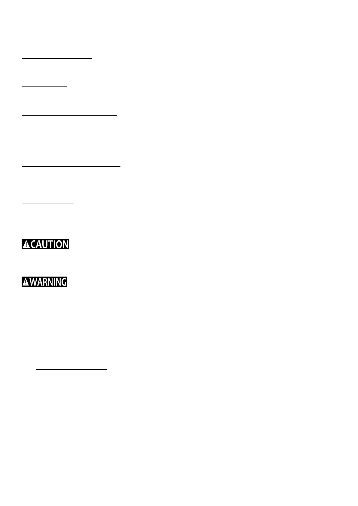
Fig.3
Fig.4
5. Assembly
ASSEMBLING CORDWRAP
1) .Insert tabs on cord wrap into slots in shell support, lining up the holes on the cord wrap with
those on the side cover.
2) Insert and tighten screws securely with screw driver.
-Tools required: Medium Phillips screw driver, 5/16’ open end or adjustable wrench, needle
nose pliers.
ASSEMBLING FRAME AND WHEELS
1) Slide axle through holes in wheel support frame.
2) Slide Wheels onto each axle, being sure that the valve stem (if pneumatic) is to the outside
3) Slide flat washers (L) onto axle past the small hole. Insert cotter pin in axle hole and bent legs
of pin with needle nose pliers to secure.
4) Place heater on the assembled frame, making sure that the air inlet end is by the wheels, and
the mounting holes on the tank flange of the heater align with holes in frame.
5) Take the rear handle and align the mounting holes with the corresponding holes in the tank
flange/wheel frame, slide a screw through the holes and loosely attach a nut. Repeat for the
other 2 holes, then fully tighten all 6 screws and nuts.
Do not operate heater without support frame fully assembled to tank.
CAUTION

ORIGIINAL INSTRUCTIONS
8
Fig.5
6. Operation
Diesel (1-K Kerosene)
For optimal performance of this heater, it is strongly suggested that 1-K kerosene be used, 1-K
kerosene has been refined to virtually eliminate contaminants, such as sulfur. Which can cause
a rotten egg odor during the operation of the heater, However, #1 or #2 fuel oil - Diesel may
also be used if 1-K kerosene is not available. Be advised that these fuels do not burn as clean
as 1-K kerosene, and care should be taken to provide more fresh air ventilation to
accommodate any added contaminants that may be added to the heated space. Use diesel fuel
can cause excess soot production.
DO NOT use any fuel that is not approved above.
NOTE: Diesel (1-K Kerosene) should only be stored in a blue container that is clearly marked
“Diesel (1-K Kerosene)”. Never store Diesel (1-K Kerosene) in a red container. Red is associated
with gasoline.
-NEVER store Diesel (1-K Kerosene) in the living space. Diesel (1-K Kerosene) should be stored in
a well ventilated area outside the living area.
-NEVER use fuel such as gasoline, benzene, alcohol, white gas, camp stove fuel, paint thinners, or
other oil compounds in this heater (THESE ARE VOLATILE FUELS THAT CAN CAUSE A FIRE
OREXPLOSION).
-NEVER store Diesel (1-K Kerosene) in direct sunlight or near a source of heat.
-NEVER use Diesel (1-K Kerosene) heat has been stored from one season to the next. It
deteriorates over time.
OLD Diesel (1-K Kerosene) WILL NOT BURN PROPERLY IN THIS HEATER.
-Use diesel in the heater. 1-K Kerosene is a suitable substitute.
THEORY OFOPERATION
Fuel System: This heater is equipped with an air pump that operates off of the electric motor. The
pump forces air through the air line connected to the fuel tank, drawing fuel to the nozzle in the
ORIGIINAL INSTRUCTIONS
9
burner head. Air also passes through the nozzle where it mixes with the fuel and is sprayed into the
combustion chamber in a fine mist.
Quick-Fire Ignition: A transformer sends high voltage to a two pronged spark plug. The spark
ignition the fuel/air mixture as it is sprayed into the combustion chamber.
Air System: A fan is turned by the heavy duty motor, which forces air around and into the
combustion chamber, where it is super-heated and forced out the front of the chamber.
Temperature Limit Control: This heater is equipped with a temperature limit control designed to
turn the heater off should the internal temperature rise to an unsafe level, if this device activates
and turns your heater off, it may require service.
Once the temperature falls below the reset temperature, you will be able to start your heater.
Electrical System Protection: The heaters’ electrical system is protected by a circuit breaker
that protects the system components from damage. If the heater fails, check the fuse first,
and replace if necessary
Flame Sensor: The heater uses a photocell to see the flame in the combustion chamber. Should
the flame extinguish, the sensor will stop electrical current and the heater will shut off.
FUELING THE HEATER
NEVER FILL FUEL TANK INDOORS. ALWAYS FILL FUEL TANK OUTDOORS. BE
SURE THAT THE HEATER IS ON LEVEL GROUND WHEN FUELING,AND NEVER OVERFILL
FUEL TANK.
NEVER REFUEL THIS HEATER WHILE IT IS HOT OR OPERATING,FIRE OR
EXPLOSION COULD RESULT.
It is always a good idea to fire the heater outdoors for the first time. This will allow any oils used in
the manufacturing process to be burned off in a safe environment. This is initial burn should last
at least 10minutes.
7. VENTILATION
Risk of indoor air pollution. Use heater only in well ventilated areas.
Always provide a fresh air opening in the heated space of at least three square feet(2800 sq.cm) for
each 29KW/hr of heater output. Provide a larger opening if more heater will require.
-a two-car garage door raised 15.24cm (6 inches)
-a single-car garage door raised 22.86cm (9 inches)
-TWO, 76.2cm (30 inches) windows raised 38.1cm(15inches)
TO START THE HEATER
1) Fill the tank with Diesel (1-K Kerosene) until fuel gauge point to “F”
2) Be sure fuel cap is secure.
3) Plug power cord into the local correct plug. Grounded extension cord and plug
extension cord into three prong 220-240V grounded outlet. The extension cord should
ORIGIINAL INSTRUCTIONS
10
be at least six feet (1.8 meters) long.
-Extension cord wire size requirements are as follows:
-6 to 10 feet(1.8 to 3 meters),use 18 AWG wire.
-11 to 100 feet(3.4 to 30.4 meters),use 16 AWG wire.
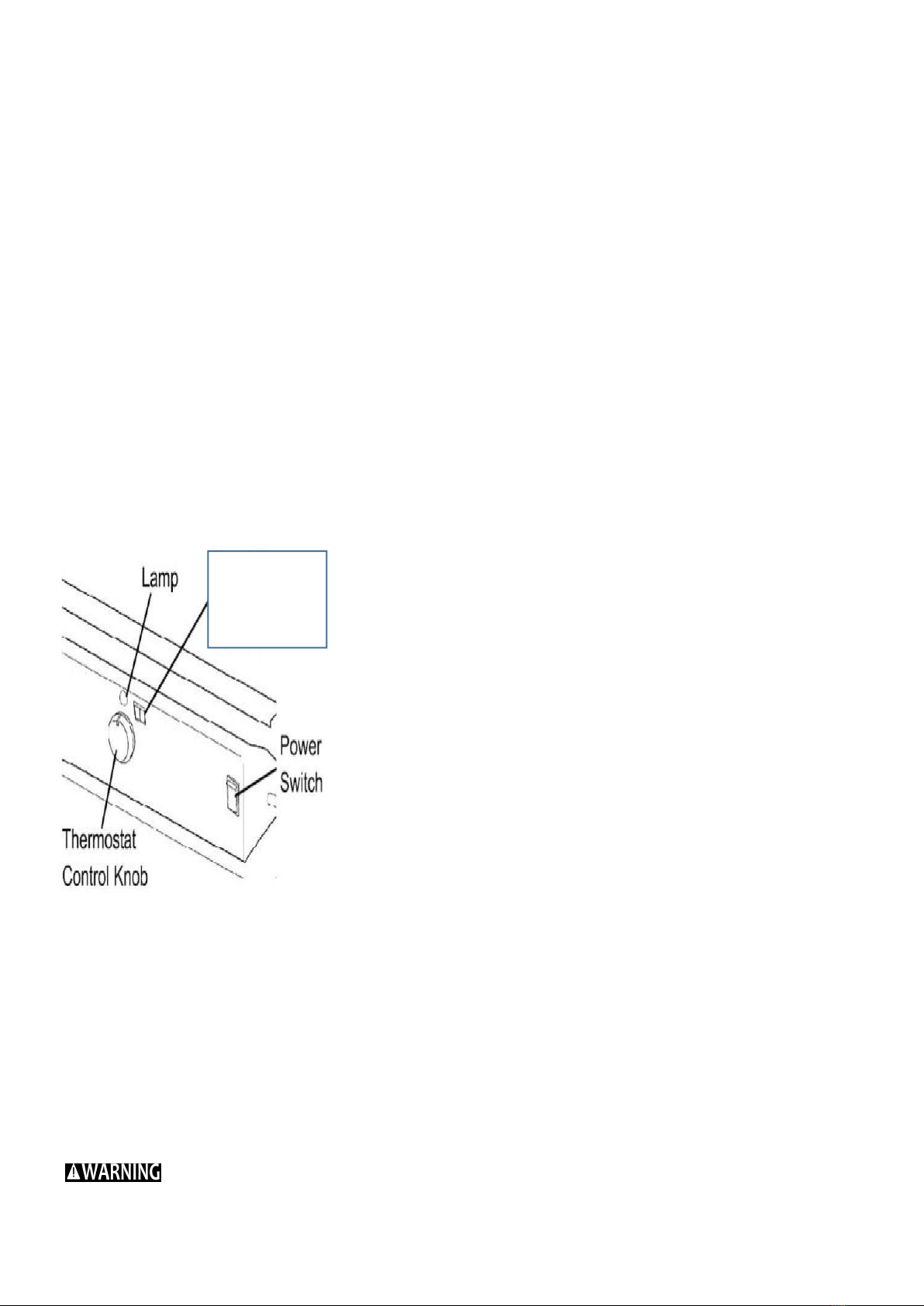
-101 to 200 feet (30.8 to 61 meters ), use 14 AWG wire. 4.Turn thermostat control knob to desired
temperature setting
The setting range is from 40°F to 110 °F. Push the power switch to the “ON” position(See
figure 9). The power indicator lamp and room temperature display will light and the heater will start.
NOTE: The room temperature display will indicate the following:
-When room temperature is less than 0°F,display will show “LO”
If the heater does not fire, the thermostat maybe set too low. Turn the control knob to a higher
setting until heater fires, if the heater still does not start, push power switch to “OFF”, then back to
“ON”. If heater still does not fire, see Troubleshooting Guide on page15
NOTE: The electrical components of this heater are protected by a fuse mounted in the PC board, if
the heater fails to fire, check the fuse first, and replace if necessary. Also check the power source to
be sure that the proper voltage is being provided to the heater.
Figure 6. Control panel
TO STOP THE HEATER
Simply turn the power switch to “OFF” position and unplug the power cord.
TO RESTART THE HEATER
1) Wait 10 seconds after shutting off the heater.
2) Turn the power switch to “ON” position.
3) Be sure to follow all starting procedure precautions.
ELECTRICAL OUTLET
Shock Hazard !
-Never plug in an appliance with more than a 5 amp rating into this outlet.
-Always keep outlet covered when not in use.
Room
temperature
display
ORIGIINAL INSTRUCTIONS
11
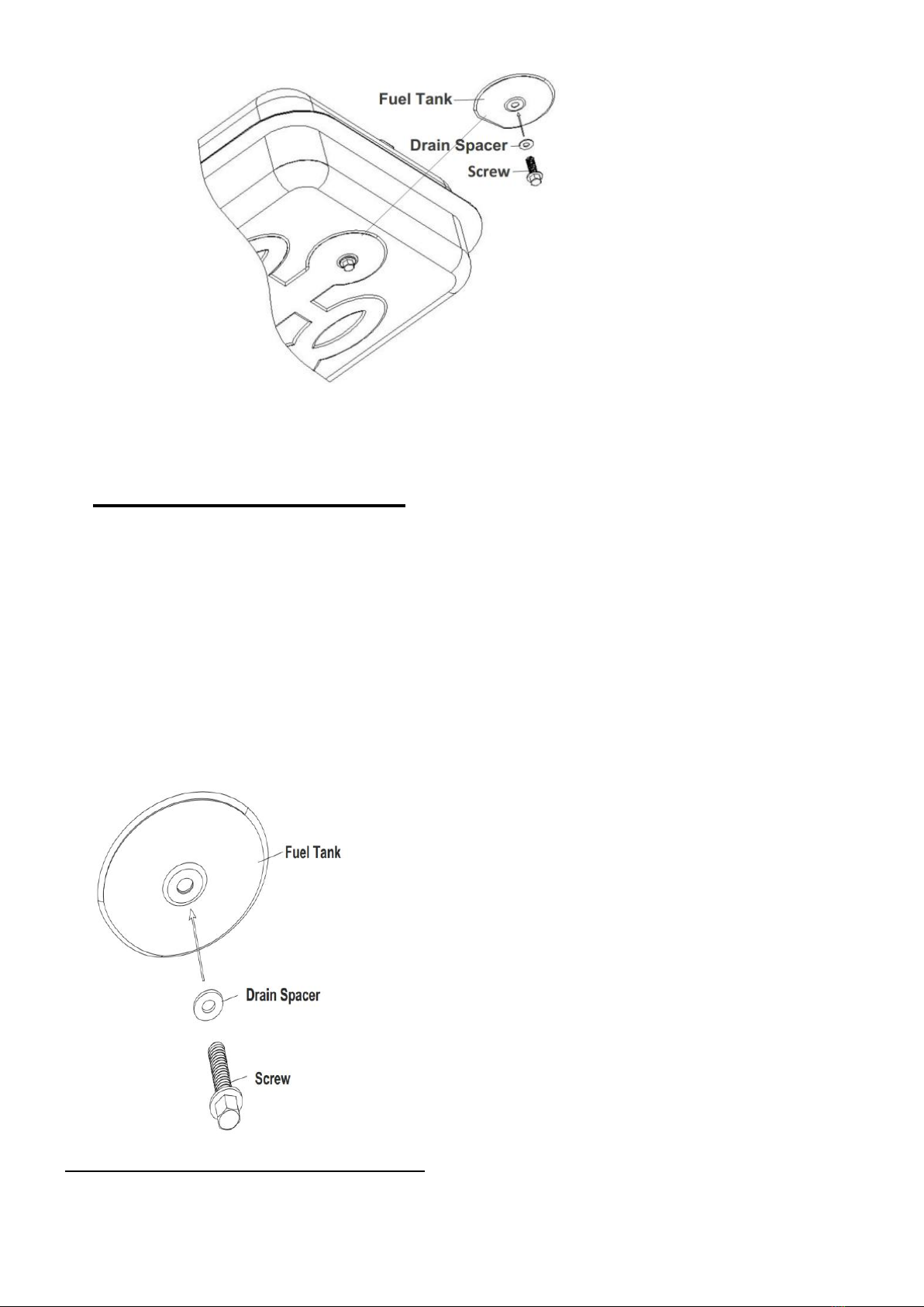
Fig 7.for Drain Plug Removal
8. LONG TERM STORAGE
Drain Fuel Tank
1) drain fuel through the Drain Plug at the bottom of the fuel tank.
2) To remove the Drain plug, Pull the plug grip downward and remove seal head from
drain hole tank.
3) Using a small amount of Diesel (1-K Kerosene). Rinse and swirl the Diesel (1-K
Kerosene) inside of the fuel tank, Empty the tank fully.
4) To replace, push the drain head fully into the drain hole and secure by pushing the
seal cap fully into the head hole (see Figure 11)
IMPORTANT: Never store leftover Diesel (1-K Kerosene) over the summer. Using old fuel
can damage your heater.
Fig. 8 for Drain Plug Reinstall
Store heater in a dry, well-ventilated area
Be sure that the storage area is free of dust and corrosive vapors. Repack the heater in the
original shipping material.
Keep the Users Manual in an easily accessible place.

ORIGIINAL INSTRUCTIONS
12
9. Maintenance
Never service heater while it is plugged in or while hot!
Use only original equipment replacement parts. The use of alternate or third party components can
cause unsafe operating conditions ,and will void your warranty.
We suggest following a maintenance schedule as follows:
FUEL/FUELTANK
Flush every 200 hours of operation or as needed. Do not use Water to flush the tank, Use fresh
Diesel (1-K Kerosene) only.
AIR FILTERS:
The air intake Filter should be replaced or washed with soap and water and dried thoroughly every
500 hours of operation, or less, depending on conditions.
The output and lint Filter should be replaced every 500 hours of operation, or less, depending on
conditions.
NOTE: Use of Diesel (1-K Kerosene) may require additional maintenance.
Figure 9. Fan Replacement
NOZZLES:
Nozzles should be cleaned or replaced at least once per heating season. Contaminated fuel
could make this necessary immediately.
To clean dirt from the nozzle, blow compressed air through nozzle front, it may be
necessary to soak nozzle in clean Diesel (1-K Kerosene) to help loosen any particles.
WARNING
ORIGIINAL INSTRUCTIONS
13
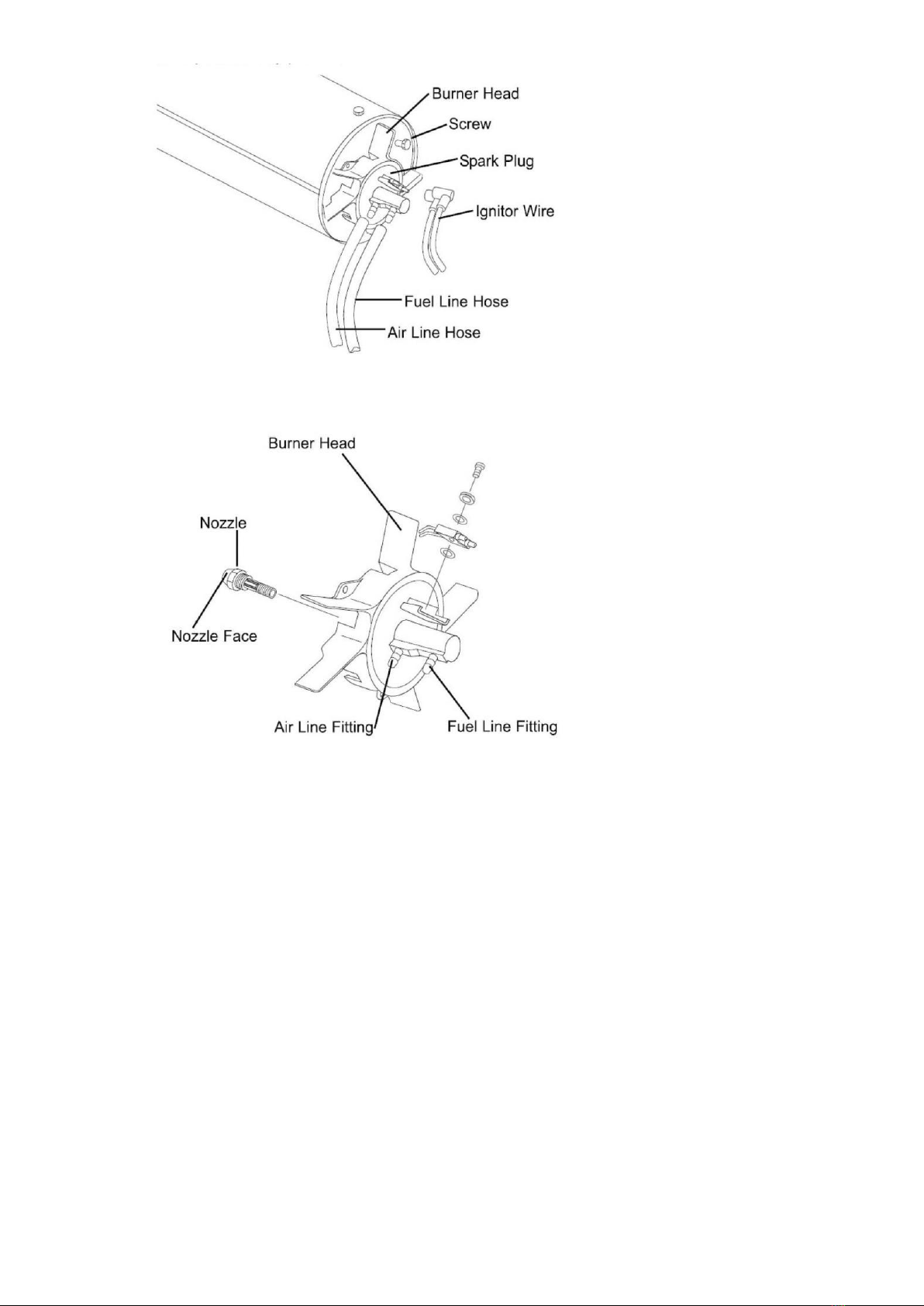
Figure 10. Nozzle Replacement.
NOTE:Use of Diesel (1-K Kerosene) may require additional maintenance. Using this heater without
proper maintenance or with contaminated or old fuel may lead to improper combustion and
possible soot production.
BE SURE FUEL USED IS APPROVED.
SPARK PLUG:
Clean and re-gap every 600 hours of operation, or replace as needed. After removing the spark plug, clean the terminals
with a wire brush. Re-gap the terminals to 0.35cm.

ORIGIINAL INSTRUCTIONS
14
Figure 11. Spark plug Replacement
PHOTOCELL:
The Photocell should be cleaned at least once per heating season or more depending on condition.
Use a cotton swap dipped in water or alcohol to clean the lens of the photocell. Note the proper
photocell position as noted in Figure 12
Figure 12. Photocell Positioning
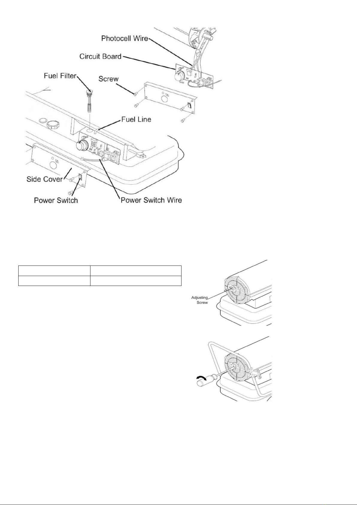
FUEL FILTER:
The fuel filter should be cleaned at least twice per heating season by rinsing, it in clean Diesel
(1-K Kerosene). Contaminated fuel could make this necessary immediately (See Figure 13).
NOTE: To remove the fuel filter for all model, please draw out the rubber plug directly. Use of diesel
may require additional maintenance. Improper maintenance can lead to poor combustion and
soot production
ORIGIINAL INSTRUCTIONS
15
Fig. 13. Fuel filter replacemen
PUMP PRESSUREADJUSTMENT:
While heater is operating, turn relief valve clockwise to increase. Counterclockwise to
decrease (see Figure 14). Use flat blade screw driver to turn valve. Correct pump
pressure is as follows
Model#
Pump Pressure(Kpa/Psi)
FCD37KW-1
38.0/5.5
Tolerance +/-10%
Figure 14. Pump pressure adjustment
ORIGIINAL INSTRUCTIONS
16
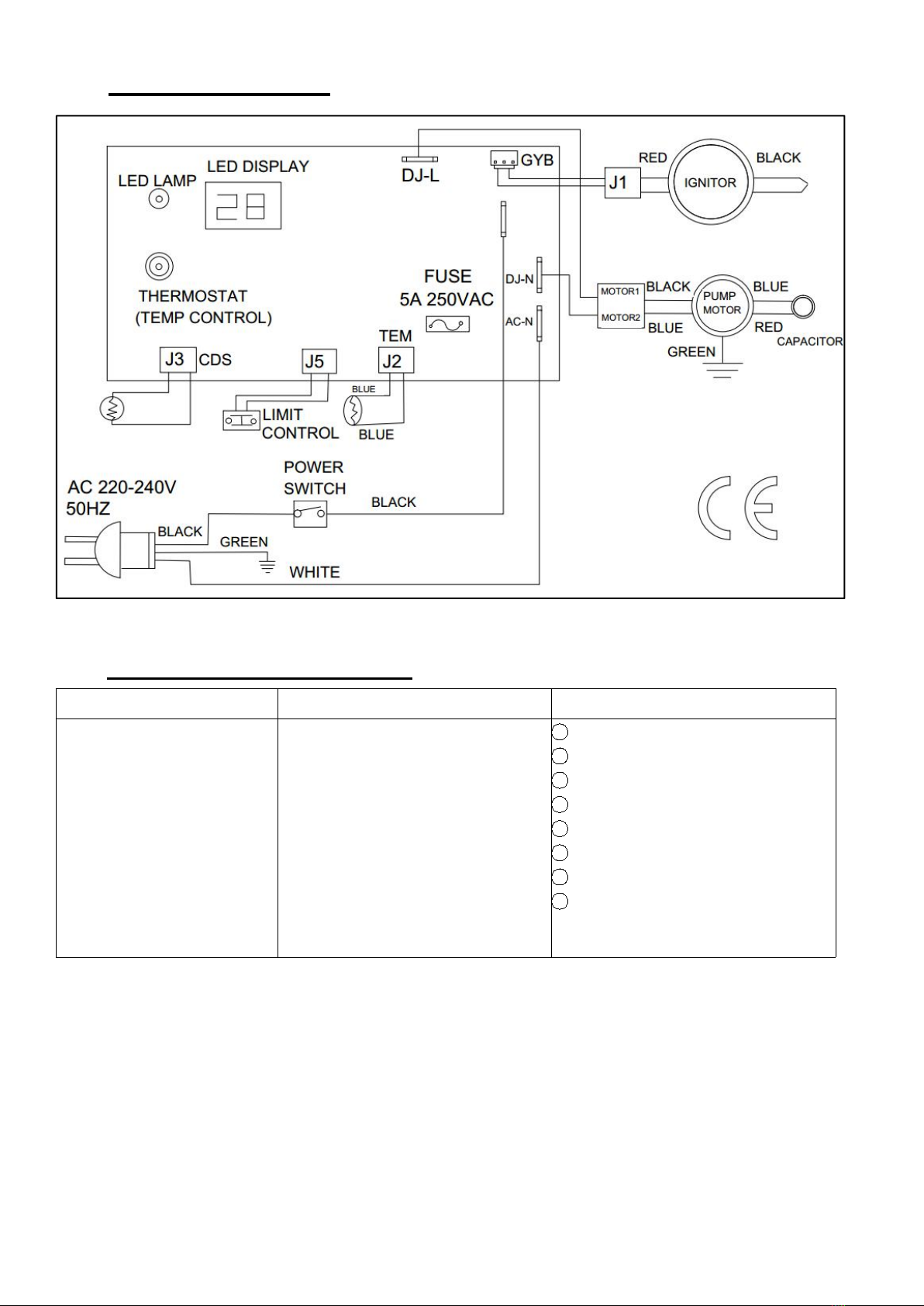
10. Wiring Diagrams
11. Troubleshooting Guide
Pr
obl
Possible Cause
Solution
Heater fires, but main PCB
shuts heater off after a short
period of time lame is
flickering, and LED display
show”E1” (1flash)
1.Incorrect pump pressure.
2.Dirty input output or lint filter
3.Dirty fuel filter.
4.Nozzle is dirty.
5.Photocell lens is dirty.
6.Photocell not installed properly.
7.Photocell defective.
8.Improper electrical connection
between main PCB and photocell.
1Adjust pump Pressure
2Clean/replace air filter
3Clean/replace Fuel Filter
4Clean/replace Nozzle
5Clean/replace Photocell
6Adjust Photocell position
7Replace Photocell
8Check wring connections (See
wiring Diagrams)

ORIGIINAL INSTRUCTIONS
17
Heater will not operate, or
motor runs for short time,
Lamp flickers and LED
display shows”E1”(1flash)
1. No Diesel in fuel tank.
2. Incorrect pump pressure.
3.Corroded spark plug or incorrect
plug gap.
4.Dirty fuel filter.
5.Dirty nozzle.
6.Moisture in fuel/fuel tank.
7.Improper electrical connection
between transformer and circuit
board.
8.
Ignitor wire not connected to
spark plug.
9.
Detective Ignitor.
1Fill tank with fresh Diesel
2Adjust pump pressure
3Clean/replace spark plug
4Clean/replace fuel filter
5Clean/replace nozzle
6Rinse out fuel tank with clean
fresh Diesel
7Inspect all electrical
connection (see wiring diagrams)
8Re-attach Ignitor wire to
spark plug
9Replace Ignitor
Fan does not opera when
heater is plugged in and
power switch is in the “ON”
position. The lamp is
flickering or on and LED
1.
Thermostat is set too low
2.
Broken electrical connection
between main PCB and motor
1.
Rotate thermostat to a higher
setting
2.
Inspect all electrical connection
(see wiring diagrams)
Lamp is flickering, and LED
display shows “E3”
(3flashes)
1.Thermostat switch has failed
1.Replace thermostat switch, wiring
diagrams
Poor combustion and / or
excess soot production
1.Dirty input output or lint filter
2.Dirty fuel filter
3.
Poor quality of fuel
4.
Pump pressure is too high or too
low
1. Clean/replace air filter
2. Clean/replace fuel filter
3. .Be sure fuel is not contaminated
or old
4. Use proper pressure
Heater does not turn on and
the lamp
Is not lit
LLLLLlLlALal
1.
Temperature limit sensor
has overheated
2.
No electrical power
3.Fuse blown
4.Improper electrical connection
between Temperature Limit Sensor
and Circuit Board
1.Push power switch to “OFF” and
allow heater to cool for 10 minutes.
Push switch back to “ON” 2.Check
power cord and extension cord to
insure of proper connection, test
power supply
3.
Check/replace fuse
4.
Inspect all electrical connection
(see wiring diagrams)
ORIGIINAL INSTRUCTIONS
18
12. DECLARATION OF CONFORMITY
DECLARATION OF CONFORMITY
BUILDER SAS
ZI, 32 RUE ARISTIDE BERGES – 312070 CUGNAUX – FRANCE
Declare that the machine designated below:
Diesel heater 37KW
ModeL : FCD37KW-1
S/N: 20200821480-20200821659
Complies with the provisions of the following European directives:
LVD Directive 2014/35 / EU
EMC Directive 2014/30 / EU
Also conforms to the following standards
Cugnaux, 24/08/2020
Philippe MARIE / PDG
Responsable du dossier technique: Mr Olivier Patriarca

WARRANTY
The manufacturer guarantees the product against defects in material and workmanship for a period of 2
years from the date of the original purchase. The warranty only applies if the product is for household use.
The warranty does not cover breakdowns due to normal wear and tear.
The manufacturer agrees to replace parts identied as defective by the designated distributor. The
manufacturer does not accept responsibility for the replacement of the machine, in whole or in part , and/or
ensuing damage.
The warranty does not cover breakdowns due to:
• insucient maintenance.
• abnormal assembly, adjustment or operations of the product.
• parts subject to normal wear and tear.
The warranty does not extend to:
• shipping and packaging costs.
• using the tool for a purpose other than that for which it was designed.
• the use and maintenance of the machine done in a manner not described in the user manual.
Due to our policy of continuous product improvement, we reserve the right to alter or change specications
without notice. Consequently, the product may be dierent from the information contained therein, but a
modication will be undertaken without notice if it is recognized as an improvement of the preceding
characteristic.
READ THE MANUAL CAREFULLY BEFORE USING THE MACHINE.
When ordering spare parts, please indicate the part number or code, you can nd this in the spare parts list
in this manual. Keep the purchase receipt; without it, the warranty is invalid. To help you with your product,
we invite you to contact us by phone or via our website:
• +33 (0)9.70.75.30.30
• https://services.swap-europe.com/contact
You must create a "ticket" via the web platform.
• Register or create your account.
• Indicate the reference of the tool.
• Choose the subject of your request.
• Describe your problem.
• Attach these les: invoice or sales receipt, photo
of the identication plate (serial number), photo
of the part you need (for example: pins on the
transformer plug which are broken).
13. WARRANTY
19

WHAT TO DO IF MY MACHINE BREAKS DOWN?
If you bought your product in a store:
a) Empty the fuel tank.
b) Make sure that your machine is complete with all accessories supplied, and clean! If this is not the case,
the repairer will refuse the machine.
Go to the store with the complete machine and with the receipt or invoice.
If you bought your product on a website:
a) Empty the fuel tank.
b) Make sure that your machine is complete with all accessories supplied, and clean! If this is not the case,
the repairer will refuse the machine.
c) Create a SWAP-Europe service ticket on the site: https://services.swap-europe.com When making the
request on SWAP-Europe, you must attach the invoice and the photo of the nameplate (serial number).
d) Contact the repair station to make sure it is available before dropping o the machine.
Go to the repair station with the complete machine packed, accompanied by the purchase invoice and the
station support sheet downloadable after the service request is completed on the SWAP-Europe site
For machines with engine failure from manufacturers BRIGGS & STRATTON, HONDA and RATO, please
refer to the following instructions.
Repairs will be done by approved engine manufacturers of these manufacturers, see their site:
• http://www.briggsandstratton.com/eu/fr
• http://www.honda-engines-eu.com/fr/service-network-page;jsessionid=5EE8456CF39CD572AA2AEEDFD
290CDAE
• https://www.rato-europe.com/it/service-network
Please keep your original packaging to allow for after-sales service returns or pack your machine
with a similar cardboard box of the same dimensions.
For any question concerning our after-sales service you can make a request on our website https://
services.swap-europe.com
Our hotline remains available at +33 (9) 70 75 30 30.
14. PRODUCT FAILURE
20
Table of contents
Other Feider Machines Heater manuals

Popular Heater manuals by other brands


Andrew James
Andrew James AJ000746 manual

Rointe
Rointe D SERIES user manual

Ecostrad
Ecostrad THERMAGLO instruction manual

Webasto
Webasto AirTop 2000 S Operating, and servicing instructions

USSC
USSC Ashley EC95 Installation, operation and maintenance instructions

Webasto
Webasto Air Top 2000 Operating, and servicing instructions

Cedar Ridge
Cedar Ridge MD3TPF user manual

Bionaire
Bionaire BOH1501 instruction manual

Vitek
Vitek VT-1701 Manual instruction

Nesco
Nesco Spa Pro SP-08 user manual

Heat Outdoors
Heat Outdoors UMBRA Plinth Safety instructions and operation manual

Heatilator
Heatilator GBI25 Series Installation & operating instructions