FeiYu Tech Y6 User manual

FeiYuTech
GuilinFeiyuElectronic TechnologyCo., Ltd
Rm.B305, InnovationBuilding, InformationIndustryPark,ChaoyangRoad,Qixing
District,GuiLin, CN
!"#$$%%%&'()*+,-(.&./01111112
Email:feiyudz@yahoo.cn
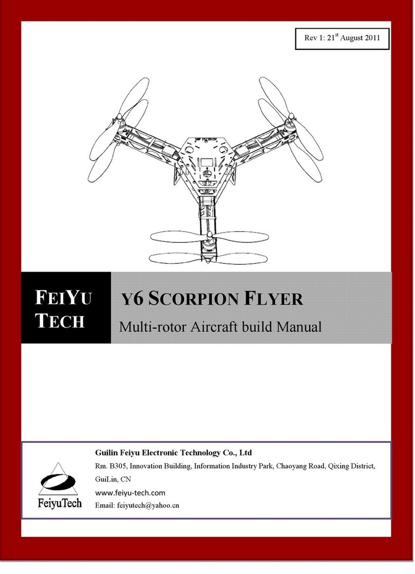
FeiYuY6 scorpion Copter
FrameInstructionManual
Pleasereadthemanual carefullybeforeusingFeiYuY6

FeiYuTech
GuilinFeiyu Electronic co.,Ltdhttp://www.feiyu-tech.comEmail:feiyudz@yahoo.cn 1
Features
1. Dimensions
2. EmptyFrameWeight:630g(receiverand batterynot included)
3. PayloadCapability:900g(battery, receiver, and cameraincluded)
4. MaximumGross Take-OffWeight: 1430g. DO NOTOVERLOADON FeiYuY6WHICHCAN
LEADTODANGER.
5.Airborneperiod: >10mins(with3S2200mAhbattery)
6. Cell Chemistry:3S1500mAh~5000mAhLithiumPolymer,andinstant dischargecapacity>15C.
SupportPWMnormalESC.
7.Caninstall FY91Q.needsatleast4channelstoflyyouraircraft.WerecommendyoutouseRC
devicewith5channelsormoreforexpansion.Supportmost.Compatiblewithall theRC devices.
Note:FirstandForemost isSafety.ThisisNotAToy.Usedextreme caution whenoperatingtheY6.
DoNot FlyoverCrowdsoroverpeople.DoNot useit asachase copter.
450mm
681mm

FeiYuTech
GuilinFeiyu Electronic co.,Ltdhttp://www.feiyu-tech.comEmail:feiyudz@yahoo.cn 2
Install
Toolsneededto buildthe Y6:
lSolderingIron
lRosenCoreSolder
lAllenWrench(provided)
Step1:FrameArmAssembly
Note: Thereare threeLEDon thesideof arm,TheLED shouldon outside.
UnpacktheFrames, separatethemas tocolorofl.e.d. si.e. Blue,Red,Green.
Removethem3x5mmbuttonheadscrews.
Removethem3x30mmpillars.
Unpackthefourmotormountplates.
Unpackthefourmotors.
Unpackthefourlandinggears.
Takeamotormountplateand usingtheallenwrenchprovided,attachthemotorto theplatewith four
M3 5mm
Scoket Screw
M3*5mm
ScoketScrew
Brushless motro
prop
Leg
Right Arm
LeftArm
soldering point
soldering point
M3 30mmPillar

FeiYuTech
GuilinFeiyu Electronic co.,Ltdhttp://www.feiyu-tech.comEmail:feiyudz@yahoo.cn 3
m3x5mmbutton headscrews.Laythisaside.
Takefourm3x30 mmpillars,usingtheallenwrenchandm3x5mmbutton headscrew,attachthefour
pillarsto theholes in thesideframe.Makesurethattheled sarefacingtotheoutside.Takethe
oppositesideframe making suretheled sarefacingoutwardsandtheWeldpointsareon thesame end.
Donottightenthescrewsyet,Nowtakethemotorwithit smountandpositionit inthebottomslots
that arecutinthesideframes,snugdownthebutton headscrewsforthemotor.Now takethelanding
gearand position it sothelong endispointingdown.Nowtightenalleight button headscrews.
Go throughthesame procedurefortheremaining threeframes.
Inspecttheassemblies tobesurethat all themotorsandthelanding gearsareseatedproperly.
Whenassembledproperly, theFeiyuTechLogo swill befacing upright andtheWeldingpointswillall
belinedup.
Step2:Buildingthe Fuselageandattachingand Weldingthe Frames
tothe Fuselage.
UnpackthethreeFrameassemblies.Youwillnotice thattheyaremarkedwithan “A”ononeside
anda “B”ontheother.Theimportant oneistheonewiththeElectronics mountedon it.Takeeight
m3x25mmpillarsandsecurethemwiththebuttonheadscrews.Makesurethattheelectronicsare
facingupandtheledplugisonthebottom.Takeanotherfuselageplateinonehand and with the
othertakeaframe assembly,place theassemblywiththeweldpointspointingdownand insertit inthe
slotsprovidedon theelectronics fuselage.
Takefourbuttonheadscrewsandthefuselageplateandalign theplatewiththeholes forthepillars,
making surethattheotherdiecut holes lineupproperly.Lightlyscrewthethreebutton headscrews
intothepillars,nowtaketheremaining Frames and place themintheslotsprovided.
Once allframes areinsertedintothetopandbottomFuselageplates,tightenthefourbuttonhead
screwsandinsert theremainingfourscrewsandtightenthemas before.
InspecttheFrames andmakesurethattheweld pointsareseatedsnuglyintheirlocations.If

FeiYuTech
GuilinFeiyu Electronic co.,Ltdhttp://www.feiyu-tech.comEmail:feiyudz@yahoo.cn 4
necessary,loosenthescrew(s)to properlyfitthepieces.
Step3: Welding(soldering)theframestothebottomfuse plate
withthe electronics.
Toaccomplishthisyouwillneedasmall solderingironaprox.35w.
Pluginthesolderingironandwhileitiscoming totemperature,gatheryourRosenCoresolderand
safetyglasses.
Withthesolderingiron attemp.place thetiponthebottomfuseweldpoint,making surethatthetip
makescontactwithboththeframe andfuse weldpoints.Applysolderatthispoint,you willnotice
thatthesolderwillwik(Flow)smoothlyandmakeagusset. Makesureyoudon thaveacoldsolder
joint.Ineeded,reheatthejoint.Use caution as nottoOverHeatthesolderjointsas thiswill cause
themetalto curl upandawayfromthecontactpoint.
Followthisprocess fortheremainingpoints.
Now removethetop Fuselageplate,thiswillgainyouaccess totheweldpointsinsideandbetweenthe
Frames.
Once inspectedand surethatnocoldsolderjointsarethere.Connecta3SLipoBalanceplugtothe
plugonthebottomoftheFuselage.
You shouldhavealltheled slitand thebottomwilllight up Whiteandwillflashforafewseconds
Cross anytwowire,
change
Motorrotati
on
welding
ESC
Fuselagewith
Electronic
components
Magiccable
tiethrough
square groove
M3 25mmPillar

FeiYuTech
GuilinFeiyu Electronic co.,Ltdhttp://www.feiyu-tech.comEmail:feiyudz@yahoo.cn 5
thenglowsteady.Ifsomeof theled sdonotlight ,inspectall yourweldpoints.Youcanalsotakea
voltmeterandonDCrange,checkforpropervoltageAprox. 2.3vdcispresentat theweldpoints.
Onceyou have theled sinspected,removethebattery,place thefuselageyou removedpreviouslyand
place eightbuttonheadscrewsinthecorresponding holesand tightenthem.
TheMagiccabletieuseforfixedbattery.
Theframe Powerdetectionsupport 3S(11.1V)battery.Connect a3SLipoBalanceplugtotheplugon
thebottomoftheFuselage.
Power detection: FuselageLedflash.
StatusLEDonSlowflash Mediumflash Fastflash
battery>11.5V11.1V~11.5V 10.8V~11.1V<10.8V
note Enoughpower Voltage
reduction NeedlandingLanding
immediately
Step4:InstallingtheESC sandthe Batteryconnector.
Takethesixesc sout of theirpackage,Thisisanimportant steptobeobserved.Onfiveoftheesc s,
removethe “Red”positiveleadfromtheservo connector.Place asmallpieceofShrinktubing over
thewireas nottocause ashort.
ThisisdoneastheFY91Q andtheCompass moduleneedsonlyonepowersource..
Connectthethreebluewires withthefemaleconnectorstothemotorleads.Asfornowyou don t
needtoworryabout directionthemotoristurning.
Dothisforall sixmotorsand esc s.Runningthewires betweenthepillarsandthesides oftheframes,
poketheservoconnectorsup throughthetopFuselageplateateachpoint correspondingtoeachmotor.
RuneachJSTBatterymaleplug throughthesameholeastheservo lead.
InsertthemaleplugsfromtheBatteryplugassemblyasindicatedonthephoto,attacheachFemale
JSTtoeachoftheplugs.
M3 30mmPillar
M3 5mm
ScoketScrew
Fron
t
M3 25mmPillar
Powercablethrough
Roundhole
6ESCswire
through
out

FeiYuTech
GuilinFeiyu Electronic co.,Ltdhttp://www.feiyu-tech.comEmail:feiyudz@yahoo.cn 6
Propellerinstallation
Pay attention totheinstallationof thepropellerdirection.
END...
2
3
6
5
1
Front
4
Y6SCORPIONFLYER
1(top) =ESC1CW
2 (top) =ESC2CW
3 (top) =ESC3CW
4 (bottom) =ESC4CCW
5(bottom) =ESC5CCW
6(bottom) =ESC6CCW
cw =clockwise
ccw =counterclockwise
Table of contents
Other FeiYu Tech Quadcopter manuals
