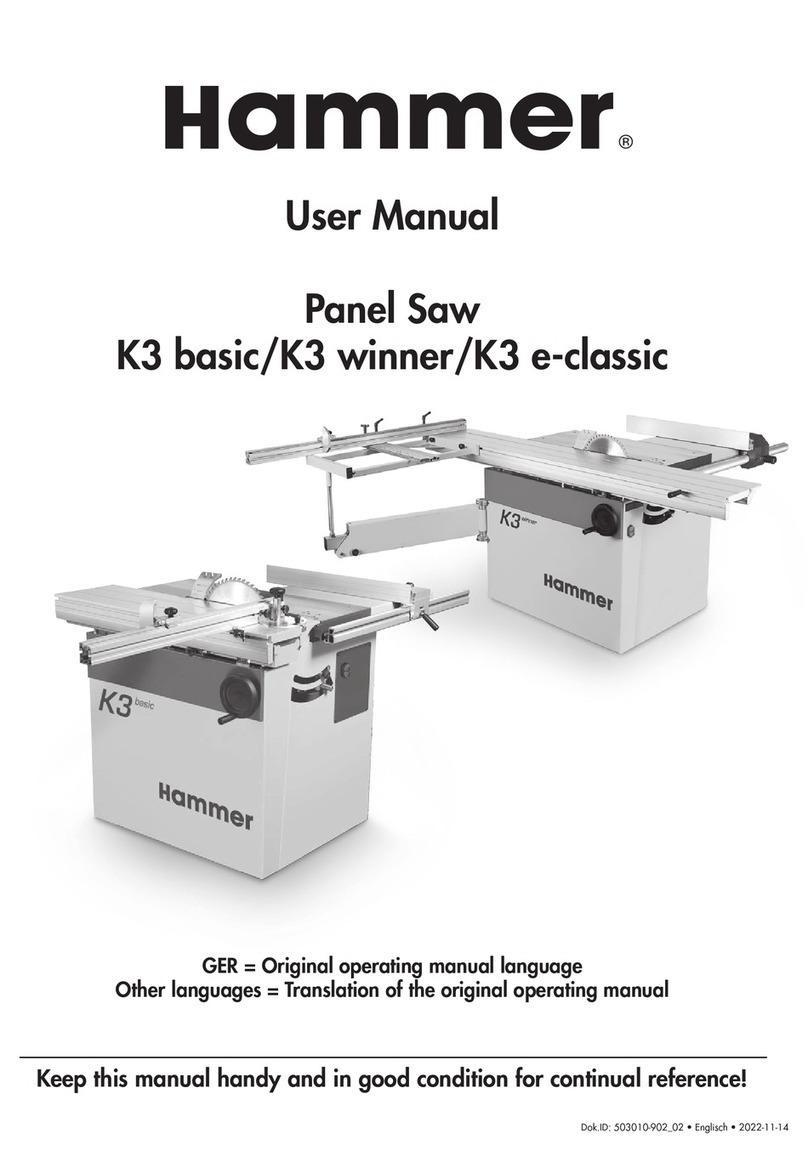
Felder 700 Series User manual

BETRIEBSANLEITUNG
OPERATION MANUAL
MANUAL D`INSTRUCTION
© 09/99 • FELDER- AUSTRIA • V1/99 S1
...und Sie machen mehr
aus Holz

Sehr geehrter Kunde !
Wir gratulieren Ihnen zum Kauf Ihrer FELDER Maschine. Bitte nehmen Sie sich die Zeit, dieses Handbuch sorgfältig
durchzulesen. Diese Betriebsanleitung bietet Ihnen alle nötigen Informationen über die sichere Verwendung und Instand-
haltung Ihrer neuen Maschine.
Setzten Sie die Maschine erst in Betrieb, nachdem Sie diese Betriebsanleitung gelesen haben.
Alle Anleitungen, Abbildungen, Angaben und technischen Daten beziehen sich auf den neuesten Produktionsstand der
zur Zeit des Druckes gegeben war und dürfen nicht ohne schriftliche Genehmigung abgedruckt oder vervielfältigt wer-
den. Wir behalten uns das Recht vor, jederzeit Änderungen vorzunehmen.
Um Ihnen einen jahrelangen, reibungslosen und störungsfreien Betrieb Ihrer FELDER- Maschine gewährleisten zu können,
steht die Fa. Felder bei Problemen und Fragen bezüglich Ihrer Maschine gerne zur Verfügung.
Wir bedanken uns, daß Sie sich für eine FELDER- Maschine entschieden haben und wünschen Ihnen in den
kommenden Jahren viel Erfolg und Freude mit Ihrer FELDER- Maschine.
Ihre Fa. Johann FELDER.
DEUTSCH
Dear customer !
Congratulations on the purchase of your FELDER machine. Please take the time to read this manual with care. This ope-
rating manual will provide all of the information required for the safe operation and maintenance of your machine.
Do not operate the machine until you have read this manual.
All of the instructions, illustrations, figures and specifications were up to date at the time of printing. They may not be
printed or copied without written permission. We reserve the right to make modifications at any time.
We will be at your disposal in the event of problems or questions in order to ensure many years of trouble-free operation
of your FELDER machine.
Thank you for choosing a FELDER machine and we wish you
much success and happiness in the coming years.
The Johann FELDER Co.
ENGLISH
Egregio Cliente !
Congratulazioni per l’acquisto della vostra macchina FELDER. Vi preghiamo di leggere con cura questo Manuale.
Queste istruzioni per l’uso contengono tutte le informazioni necessarie per un impiego e una manutenzione sicuri
della vostra nuova macchina.
Mettete in funzione la macchina solo dopo aver letto questo Manuale di Istruzioni.
Tutte le istruzioni, figure, indicazioni e dati tecnici si riferiscono all’ultimo stato di produzione al momento della stampa
di questo manuale e non devono essere ristampate o duplicate senza autorizzazione scritta. Ci riserviamo il diritto di
effettuare in qualsiasi momento delle modifiche.
Per poter garantire alla vostra macchina FELDER un funzionamento negli anni, senza difficoltà o guasti, la Ditta Felder è
a vostra disposizione per qualsiasi problema o domanda riguardante la vostra macchina.
Vi ringraziamo per aver scelto una macchina FELDER e vi auguriamo nel prossimo
anno molto successo e soddisfazione con la vostra macchina FELDER.
La vostra Ditta Johann FELDER.
ITALIANO

V01B05C02K01 A01F01S01
VORWORT
MASCHINEN-
BESCHREIBUNG
KOMBIANSCHLAG
KREISSÄGEAGGREGAT
AD- BEREICH
SERIE 7
FRÄSAGGREGAT
SCHIEBETISCHEINHEIT
STICHWORTVERZEICHNIS
PREFACE
MACHINE-
DESCRIPTION
COMBINATION FENCE
AD SECTION
SERIES 7
PREFAZIONE
DESCRIZIONE
DELLA MACCHINA
GUIDAPEZZO
COMBINATO
CAMPO AD
SERIE 7
GRUPPO SEGA
CIRCOLARE TABLESAW UNIT
GRUPPO TAVOLA
SCORREVOLE SLIDING TABLE ASSEMBLY
ALPHABETIC INDEX
INDICE ALFABETICO
GRUPPO TOUPIE SHAPING UNIT

Haben Sie schon eine Absaugung für
Ihre Maschine?
Informieren Sie sich bei Ihrem FELDER-
Händler!
Es gibt sehr viel Zubehör und Werk-
zeuge die Ihnen die Arbeit wesentlich
erleichtern und beschleunigen.
Sämtliches Maschinenzubehör ist im
FELDER-Zubehörkatalog angeführt.
Die Werkzeuge entnehmen Sie bitte
dem FELDER-Werkzeugkatalog.
Falls Sie diese Kataloge noch nicht
besitzen, fordern Sie diese bitte mit
der am Umschlag hängenden Ant-
wortkarte an.
Do you already have a dust collector
for your machine?
Your FELDER dealer will be pleased to
inform you!
There are many accessories and tools
that simplify and speed up your work.
All machine accessories are described
in the FELDER accessory catalog.
Please refer to the FELDER tool catalog
for all tools.
If you don’t have these catalogs alrea-
dy, please request them with the post-
card attached to the cover.
Avete già un sistema di aspirazione
per la vostra macchina?
Rivolgetevi al vostro rivenditore
FELDER!
Sono disponibili moltissimi accessori e
utensili che potranno facilitare e acce-
lerare le operazioni in maniera evi-
dente.
Tutti gli accessori della macchina sono
contenuti nel catalogo accessori
FELDER. Il catalogo utensili FELDER
contiene tutti gli utensili.
Se non foste ancora in possesso di
questo catalogo, richiedetelo tramite
la cartolina allegata in copertina.

V01 V2/2000 S1 - 1 -
V01
Gewährleistung /
Garantie................
Allgemeines zu
Lagerung / Trans-
port ......................
Allgemeine Auf-
stellungsbedingun-
gen........................
Allgemeine
Betriebshinweise ..
Die richtige
Absaugung..................
Allgemeine Hinweise
zur Sicherheit ..............
Elektrischer
Anschluß ..............
Automatische
Bremseinrichtung ..
V01-1)
V01-2)
V01-3)
V01-4)
V01-4.1)
V01-4.2)
V01-5)
V01-6)
2
4
5
5
6
6
7
8
Kapitel Seite
V01 VORWORT
Warranty ..............
General informati-
on on storage /
transport ..............
General conditions
of installation ........
General operating
information............
The proper
dust collector ................
General safety informa-
tion..............................
Electrical connec-
tion........................
Automatic braking
system ..................
V01-1)
V01-2)
V01-3)
V01-4)
V01-4.1)
V01-4.2)
V01-5)
V01-6)
2
4
5
5
6
6
7
8
Chapter Page
V01 PREFACE
Garanzia ..............
Informazioni gene-
rali su
Conservazione /
Trasporto ..............
Condizioni generali
di installazione ......
Istruzioni generali
per il funzionamen-
to ..........................
La corretta
aspirazione..................
Indicazioni generali
sulla sicurezza..............
Allacciamento
elettrico ................
Impiano freno
automatico ............
V01-1)
V01-2)
V01-3)
V01-4)
V01-4.1)
V01-4.2)
V01-5)
V01-6)
2
4
5
5
6
6
7
8
Capitolo pag.
V01 PREFAZIONE

- 2 - V01 V2/2000 S1
V01-1)
Gewährleistung / Garantie
Es gelten die nationalen
gesetzlichen Bedingungen mit
folgender Maßgabe :
•Die Gewährleistungsfrist beginnt mit
Übergabe der Ware.
•Voraussetzung für jegliche Gewährlei-
stung ist die vollständige Bezahlung
des Kaufpreises, sowie die genaue
Beachtung folgender Vorgaben :
Betriebsanleitung,
Transportbedingungen,
Lager- und Konservierungsbedingun-
gen,
Aufstellungsbedingungen,
bestimmungsgemäße Verwendung,
Bedienungsanweisungen,
Wartungs- und Pflegeanleitungen (ins-
besondere Intervalle),
Verwendung von FELDER Originaltei-
len.
Soweit es um die Genauigkeiten geht :
Aufstellung, Inbetriebnahme und Ein-
weisung durch FELDER-ausgebildetes
Fachpersonal.
Bei rauhem Transport, Treppentrans-
port oder Transport bei dem die
Maschine zerlegt werden muß: Monta-
ge und Einstellung durch FELDER-aus-
gebildetes Fachpersonal.
•Die Wahl des Gewährleistungsbehelfes
(Verbesserung, Austausch, Preisminde-
rung etc.) obliegt der Fa. FELDER.
Auf Verlangen ist der Käufer verpflich-
tet, die Ware bzw. den mangelhaften
Teil auf seine Kosten der Fa. FELDER
zu übermitteln.
•Reklamationen müssen schriftlich erfol-
gen und jedenfalls die Maschinennum-
mer und eine möglichst genaue Män-
gelbeschreibung enthalten.
•Etwaige Mängel sind innerhalb der
gesetzlichen Gewährleistungsfrist
schriftlich geltend zu machen.
V01-1)
Warranty
The national laws shall
apply, subject to the
following proviso:
•The warranty period begins with the
transfer of the merchandise.
•The payment of the purchase price in
full shall be a precondition to any war-
ranty claims, as well as the complete
observation of the stipulations contai-
ned in the:
Operating manual,
Transport conditions,
Storage and protection conditions,
Installation conditions,
Proper use,
Operating instructions,
Maintenance and care instructions
(especially intervals),
and the use of genuine FELDER repla-
cement parts.
With regard to the details:
Installation, commissioning and instruc-
tion by technicians trained by FELDER.
In the event of rough transport, trans-
port via stairs or situations in which the
machine must be disassembled:
Assembly and adjustment by technici-
ans trained by FELDER.
•The type of warranty performance
(improvement, replacement, reduction
in price, etc.) shall be at the discretion
of FELDER.
The buyer shall undertake to ship the
merchandise or defective part to FEL-
DER at his own expense.
•Warranty claims must be made in writ-
ing and must contain the machine
number and a precise description of
the defect.
•Warranty claims must be made during
the statutory warranty period.
V01-1)
Garanzia
Sono valide le condizioni
definite dalle legge nazionali
nelle seguenti misure :
•Il periodo di garanzia inizia alla con-
segna della merce.
•Presupposto per ogni garanzia è il
pagamento completo del prezzo di
vendita, nonché la completa osservan-
za delle seguenti indicazioni :
Manuale di istruzioni
Condizioni di trasporto,
Condizioni di conservazione e stoc-
caggio,
Condizioni di installazione
Utilizzazione conforme alle norme:
Istruzioni per l’utilizzo,
Istruzioni di manutenzione e cura (spe-
cialmente gli intervalli di manutenzio-
ne),
Utilizzo di parti originali FELDER.
Come precisazione vale quanto segue
:
Installazione, messa in funzione e
addestramento effettuato da personale
qualificato FELDER.
Per il solo trasporto, trasporto su scale
o trasporto in cui la macchina debba
essere smontata: Montaggio e regola-
zione a cura del personale qualificato
FELDER.
•La decisione in merito ad eccezioni
alla garanzia (migliorie, sostituzione,
diminuzione di prezzo ecc.) spetta alla
Ditta FELDER.
Su richiesta l’acquirente è obbligato a
sue spese a comunicare alla ditta FEL-
DER il materiale e/o le parti difettose.
•I reclami devono essere effettuati per
iscritto e comunque contenere il nume-
ro di macchina e una descrizione pos-
sibilmente precisa del difetto.
•Eventuali difetti devono essere conte-
stati per iscritto entro il periodo di vali-
dità della garanzia.

V01 V2/2000 S1 - 3 -
V01
•Ausgeschlossen sind jedenfalls
Ansprüche :
- Die auf unsachgemäße Handhabung
oder äußere Krafteinwirkung zurückzu-
führen sind
(z.B. Kratzer, Dellen, Verbiegungen);
- aus optischer Abnützung und laufendem
Gebrauch
(z.B. Lackierbeschädigungen, Kratzer);
- durch Verunreinigung jeder Art verur-
sachte;
- aus unsachgemäßer, elektrischer Versor-
gung;
- aufgrund Umbau, Reparatur oder sonsti-
gen Manipulationen an der Maschine,
soweit diese nicht durch FELDER-ausge-
bildetes Fachpersonal vorgenommen
wurden;
- aufgrund Korrosion, Brand oder Wasser-
einfluß.
Ausgeschlossen ist jegliche
Haftung für Folge- und Transport-
schäden.
Darüberhinaus leistet die Fa. FEL-
DER Garantie nach folgenden
Bedingungen:
•Obige Gewährleistungsbedingungen gel-
ten sinngemäß
•Voraussetzung ist, daß die vollständig
ausgefüllte Garantiekarte binnen 14
Tagen ab Übernahme der Ware bei FEL-
DER in A-6060 Hall in Tirol, Heiligkreu-
zerfeld 18 einlangt.
•Garantie wird gewährt durch kostenlosen
Ersatz des defekten Teiles, ohne Arbeits-
leistungen wie für Montage oder Einstel-
lung und ohne Transport-, Fahr- und
Unterbringungskosten etc.
Der defekte Originalteil ist spätestens
binnen 14 Tagen an FELDER in A-6060
Hall in Tirol zurückzustellen, andernfalls
der Ersatzteil zu bezahlen ist.
•Die Garantie beträgt 3 Jahre auf alle
Ersatzteile, soweit es sich nicht um Ver-
schleißteile (z.B. Lager, Riemen, Gewin-
despindeln, Spindelmuttern, Zahnseg-
mente, Zahnräder, etc) oder Kunststofftei-
le (z.B. Griffe, Aufkleber, Stopfen, Blen-
den, Abstreifer, Walzenkäfige, etc) han-
delt.
•Die Garantie beträgt 6 Jahre für das For-
matschiebetisch- Führungssystem
•The following claims shall be excluded:
- those involving improper handling or
external application of force
(e.g. scratches, dents, bent parts);
- or deterioration of appearance due to
regular use
(e.g. damage to paintwork and scrat-
ches);
- claims relating to contamination or soi-
ling;
- or improper electrical supply;
- claims resulting from modification,
repairs or other manipulations not per-
formed by technicians trained by FEL-
DER;
- claims due to corrosion, fire or the effects
of water.
No liability shall be borne for
transport damage and conse-
quential damage.
In addition, FELDER shall honor
warranty claims under the follo-
wing conditions:
•The warranty terms stated above shall
apply correspondingly.
•A precondition is the receipt of the com-
pleted warranty card by FELDER in A-
6060 Hall in Tirol, Heiligkreuzerfeld 18
within 14 days of the receipt of the mer-
chandise.
•The guarantee shall be honored by the
replacement of the defective part free of
charge, not including services such as
installation and adjustment and not inclu-
ding transport charges, fares, accommo-
dation, etc.
The defective original part must be retur-
ned to FELDER in A-6060 Hall in Tirol,
Austria, within 14 days, otherwise the
purchase price shall become due for the
replacement part.
•A warranty period of 3 years shall apply
to all parts other than wearing parts such
as bearings, belts, threaded spindles,
spindle nuts, toothed segments, gears,
etc. or plastic parts such as grips, adhesi-
ve labels, plugs, covers, wipers, roller
cages, etc.
•A warranty of 6 years shall apply to the
panel sliding table guide system.
•Sono esclusi comunque i reclami :
- provocati da una manipolazione impro-
pria o da cause esterne
(per es. graffi, ammaccature, deforma-
zioni);
- per usura ottica e consumo continuo
(per es. danni alla vernice, graffi);
- causati da sporcizia di ogni tipo;
- derivati da alimentazione elettrica impro-
pria;
- causati da trasformazioni, riparazioni o
altre manipolazioni alla macchina, se
non fossero stati effettuati da personale
qualificato FELDER;
- causati da corrosione, incendi o acqua.
La Ditta FELDER non è responsabi-
le per qualsiasi
danno indiretto e causato dal tra-
sporto.
Inoltre la Ditta FELDER rilascia la
garanzia alle seguenti condizioni:
•Le suddette condizioni di garanzia sono
fatte valide per analogia
•Condizione preliminare è che la scheda
di garanzia compilata in tutte le sue parti
venga spedita entro 14 giorni dal ricevi-
mento della merce da FELDER in A-
6060 Hall in Tirol, Heiligkreuzerfeld 18.
•La garanzia permette una sostituzione
gratuita di parti difettose, senza presta-
zioni di lavoro come montaggio o rego-
lazione e senza costi di trasporto, vitto e
alloggio ecc.
La parte originale difettosa dev’essere
restituita al più tardi entro 14 giorni da
FELDER in A-6060 Hall in Tirol, altrimenti
il ricambio dovrà essere pagato.
•La garanzia è di 3 anni per tutti i ricam-
bi, escluse le parti di usura (per es. cusci-
netti, cinghie, viti filettate, madreviti, seg-
menti dentati, ruote dentate, ecc.) o parti
in plastica (per es. maniglie, etichette,
tappi, diaframmi, spogliatori, gabbie
portarulli, ecc.).
•La garanzia vale 6 anni per il sistema di
guida della tavola scorrevole per sagome

- 4 - V01 V2/2000 S1
V01-2)
Allgemeines zu
Lagerung / Transport
• Lagertemperatur: -10 bis +50°C
(Bei längerer Lagerung alle blanken
Maschinenteile einölen)
• Feuchtraumlagerung / Übersee-
transport:
Maschine dicht verpacken und vor
Korrosion schützen (Trockenmittel)
• Während dem Transport:
- Erschütterungen und Vibrationen
vermeiden
- Nicht der freien Witterung ausset-
zen
• Schwerpunkt der Maschine beach-
ten ! -> KIPPGEFAHR
• Bei Maschinen AD 731, AD 741,
CF 731 (S) und CF 741 (S) bei län-
gerem Stillstand Getriebehebel G
auf ”O” stellen.
Siehe Kapitel A01 / A02
• Durch den Transport können sich
die Digitaluhren verstellen.
Zur genauen Einstellung die Uhr U
durch Öffnen der Klemmschraube K
aus dem Handrad nehmen, und
solange drehen, bis sie den gemes-
senen Wert eines zuvor bearbeite-
ten Probewerkstückes genau
anzeigt.
Die Uhr wieder in das Handrad
hineinstecken und mit der Klemm-
schraube Kvorsichtig fixieren.
Abb 02
K
U
V01-2)
General information on
storage / transport
• Storage temperature: -10 to +50°C
(oil all bare metal parts before lon-
ger periods of storage)
• Storage in humid environments /
overseas transport:
Pack the machine thoroughly and
protect it against corrosion (drying
agent)
• During transport:
- Avoid mechanical shocks and vibra-
tion
- Do not expose to the elements
• Take the machine’s center of gravity
into account! -> DANGER OF TIP-
PING
• On the machines AD 731, AD 741,
CF 731 (S) and CF 741 (S), set the
gear lever Gto “O” during longer
periods without use.
See Section A01 / A02
• The digital indicators may lose their
calibration during transport.
To set the indicator Uprecisely,
open the clamping screw Kand
remove from the handwheel. Turn it
until the measured value of a pre-
viously processed workpiece is pre-
cisely displayed.
Reinsert the indicator into the hand-
wheel and carefully tighten the
clamping screw K.
V01-2)
Informazioni generali su
Conservazione / Trasporto
• Temperatura di conservazione: da -
10 a +50°C
(in caso di prolungata conservazio-
ne oliare tutte le parti macchina
non verniciate)
• Conservazione in luogo umido /
trasporto via mare:
Imballare bene la macchina e pro-
teggerla dalla corrosione (disi-
dratante)
• Durante il trasporto:
- Evitare scossoni e vibrazioni
- Non esporre la macchina all’aria
aperta
• Fare attenzione al baricentro della
macchina ! -> PERICOLO DI
RIBALTAMENTO
• Nelle macchine AD 731, AD 741,
CF 731 (S) e CF 741 (S), in caso di
arresto prolungato posizionare la
leva del meccanismo Gsu “O”.
Vedere capitolo A01 / A02
• A causa del trasporto gli orologi
digitali possono spostarsi.
Per una regolazione precisa, toglie-
re l’orologio Udal volantino apren-
do la vite di serraggio Ke girare
fino a quando non venga indicato il
valore misurato da un pezzo di
prova precedentemente lavorato.
Inserire nuovamente l’orologio nel
volantino e fissarlo con cautela per
mezzo della vite di serraggio K.

V01-3)
Allgemeine Aufstellungs-
bedingungen
Folgende Punkte sind zu Beachten:
• Es muß ausreichend Platz in einem
geschlossenen, trockenen Raum zur
Verfügung stehen
(Siehe »Maschinenbeschreibung«)
• Betriebstemperatur:
+10 bis +40°C Raumtemperatur
(bei Nichteinhaltung entstehen
Lagerdefekte!)
• Maschine, Werkzeuge, Zubehör etc
für Kinder unerreichbar aufbewah-
ren -> Verletzungsgefahr
• Absaugschläuche und elektrische
Leitungen so verlegen, daß nie-
mand darüberstolpern kann.
V01-4)
Allgemeine Betriebshinweise
• Alle Skalen sind nur voreingestellt
(Sie müssen auf das jeweilig ver-
wendete Werkzeug einjustiert wer-
den.)
• Vor der ersten Inbetriebnahme müs-
sen alle blanken Teile von den Kon-
servierungsmitteln gereinigt wer-
den.
• Alle Einstellungen vor Anfertigen
von Serien mit Probearbeitsgang
überprüfen und eventuell korrigie-
ren.
Die Maschine darf nur von Personen
betrieben werden, denen die Bedie-
nung, die Arbeitstechniken sowie die
Unfallverhütungsvorschriften dieser
Maschine bekannt sind.
V01 V2/2000 S1 - 5 -
V01
V01-3)
General conditions of installa-
tion
Observe the following points:
• An adequate amount of space must
be available in a closed, dry room.
(see “Machine Description”)
• Working temperature:
+10 to +40°C ambient temperature
(bearing damage will result if this
range is not maintained!)
• Keep the machine, tools, accesso-
ries, etc. out of the reach of child-
ren -> danger of injury
• Install vacuum hoses and electrical
cables in such a manner that they
are not a tripping hazard.
V01-4)
General operating information
• All scales are only preset (they must
be calibrated to the specific tool).
• Before initial use, preservative
agents must be removed from all
bare metal parts.
• Before doing serial work, check all
settings with a test run and adjust
as required.
The machine may only be operated by
persons familiar with the operation,
working techniques and accident-pre-
vention regulations pertaining to it.
V01-3)
Condizioni generali per
l’installazione
E’ necessario attenersi ai seguenti
punti:
• Dev’essere disponibile sufficiente
spazio in un locale chiuso e asciutto
(vedere “Descrizione della macchi-
na”)
• Temperatura d’esercizio:
da +10 a +40°C temperatura
ambiente
(in caso d’inosservanza risulteran-
no dei difetti ai cuscinetti!)
• Conservare la macchina, gli uten-
sili, gli accessori ecc. lontano dalla
portata dei bambini -> Pericolo di
lesioni
• Posare i flessibili di aspirazione e le
linee elettriche in modo che nessu-
no le possa calpestare.
V01-4)
Istruzioni generali per il fun-
zionamento
• Tutte le scale sono solo preregolate
(devono essere regolate sul rispetti-
vo utensile utilizzato.)
• Prima della messa in funzione ini-
ziale tutte le parti non verniciate
devono essere ripulite dal prodotto
usato per la conservazione.
• Controllare con una prova tutte le
regolazioni prima della produzione
in serie ed eventualmente correg-
gerle.
La macchina può essere azionata solo
da persone che conoscano i comandi,
le tecniche di lavoro e le norme di
prevenzione infortuni di questa
macchina.

- 6 - V01 V2/2000 S1
V01-4.1)
Die richtige Absaugung
Grundsätzlich muß jedes Aggregat
bei der Verwendung abgesaugt wer-
den.
Als Zubehör erhältlich ist eine anlauf-
verzögerte Steckdose.
Weiters muß die Absaugleistung groß
genug sein, um die geforderten Unter-
drücke und eine Luftgeschwindigkeit
von 20m/s an der Anschlußstelle zu
erbringen.
Siehe »Technische Daten«
Achtung:
Absaugschläuche müssen schwer ent-
flammbar und elektrisch leitend sein!
Verwenden Sie deshalb nur original
FELDER- Absaugschläuche!
V01-4.2)
Allgemeine Hinweise zur
Sicherheit
Folgende Punkte sind zu Beachten:
• Es dürfen nur Holz und ähnlich zer-
spanbare Materialien bearbeitet
werden.
• Es dürfen nur Werkstücke bearbeitet
werden, die sicher aufgelegt und
geführt werden können.
• Vor der Bearbeitung jedes Werk-
stück auf Fremdkörper wie z.B.
Nägel, Schrauben untersuchen.
• Achten Sie auf die richtige Drehrich-
tung des jeweiligen Aggregates.
• Vor dem Einschalten immer kontrol-
lieren ob das Werkzeug frei läuft.
• Sämtliche Einstellungsarbeiten dür-
fen nur bei stillstehendem Werkzeug
durchgeführt werden.
• Verwenden Sie die für die verschie-
denen Arbeitsgänge vorgesehenen
länderspezifischen Schutzvorrichtun-
gen!
• Vor Inbetriebnahme müssen die in
Ihrem Land geltenden Sicherheitsbe-
stimmungen erfüllt sein.
• Die Maschine darf nur mit einer
geeigneten Absaugung betrieben
werden!
V01-4.1)
The correct dust collector
As a rule, all units must be vacuumed
during use.
A time-delayed socket is available as
an accessory.
In addition, the vacuum performance
must be sufficient to achieve the requi-
red negative pressures and an air
speed of 20 m/s at the connector.
See »Technical Data«
Attention:
Vacuum hose must not be easily
inflammable and must conduct electri-
city!
Be sure to use only genuine FELDER
vacuum hoses for this reason!
V01-4.2)
General safety information
Observe the following points:
• The machines are designed for wor-
king wood and materials with simi-
lar cutting properties only.
• Workpieces must be securely posi-
tioned and guided.
• Before working, check each work-
piece for foreign matter such as
nails or screws.
• Observe the correct rotating direc-
tion of the specific unit.
• Before switching the machine on,
ensure that the tool runs freely.
• All adjustments may only be perfor-
med with the tool stationary.
• Always use the country-specific
safety equipment for all work opera-
tions!
• Ensure that the safety regulations of
your country have been fulfilled
before using the machine for the first
time.
• The machine may only be operated
with a suitable dust collector.
V01-4.1)
La corretta aspirazione
Ogni gruppo deve sempre essere sot-
toposto ad aspirazione prima dell’uti-
lizzo.
Come accessorio è disponibile una
presa ad avviamento ritardato.
Inoltre la potenza aspirante dev’essere
sufficientemente grande per fornire le
depressioni necessarie ed una velocità
dell’aria di 20m/s sui punti di allac-
ciamento.
Vedere »Dati tecnici«
Attenzione:
I flessibili di aspirazione devono esse-
re difficilmente infiammabili ed essere
buoni conduttori dell’elettricità.
Pertanto utilizzare solo flessibili di
aspirazione originali FELDER!
V01-4.2)
Indicazioni generali sulla sicu-
rezza
E’ necessario attenersi ai seguenti punti:
• Può solo essere lavorato legno e
materiali truciolabili simili.
• Possono essere lavorati solo pezzi
che possano essere posati e guidati
con sicurezza.
• Prima della lavorazione controllare
che ogni pezzo non contenga corpi
estranei, come per es. chiodi o viti.
• Controllare che ogni gruppo abbia
il corretto senso di rotazione.
• Prima dell’inserimento controllare
sempre che l’utensile si muova libe-
ramente.
• Tutte le operazioni di regolazione
possono solo essere eseguite con
utensile fermo.
• Utilizzare i dispositivi di protezione
specifici del paese e previsti per le
diverse operazioni.
• Prima della messa in funzione le
norme di sicurezza vigenti nel paese
di utilizzo dovranno essere soddis-
fatte.
• La macchina può solo essere azio-
nata con un sistema di aspirazione
adatto.

V01 V2/2000 S1 - 7 -
V01
Das Gerät wird ohne Stecker geliefert
und kann kundenseitig mit einem den
länderspezifischen Vorschriften entspre-
chenden Stecker ausgerüstet werden.
Die Absaugung muß so an die Maschi-
ne angeschlossen werden, daß sie
zwangsläufig mit der Maschine mitläuft.
L’apparecchio viene fornito senza
connettore e può essere equipaggiato
dal cliente con un connettore confor-
me alle norme del paese d’installazio-
ne della macchina.
Il dispositivo di aspirazione dev’essere
collegato alla macchina in modo che
funzioni obbligatoriamente insieme
con la macchina.
The unit is supplied without a plug and
can be equipped with a plug that
complies with country-specific require-
ments by the customer.
The dust collector must be connected
to the machine in such a manner that
it must run along with the machine.
V01-5)
Allacciamento elettrico
Riguardo alla parte elettrica devono
sussistere le seguenti condizioni:
• La macchina dev’essere collegata a
massa tramite conduttore di prote-
zione
• L’oscillazione di tensione nella rete
elettrica può essere al massimo del
±10% della tensione nominale
• La qualità del cavo di collegamento
dev’essere del tipo 4x2,5 H07RN-F
o almeno equivalente
• L’alimentazione di corrente
dev’essere protetta da danneggia-
menti, per es. con tubi corrazzati
• I flessibili di aspirazione allacciati
devono essere collegati a massa
contro cariche elettrostatiche.
ATTENZIONE!
Le seguenti operazioni possono essere
effettuate solo da un elettricista specia-
lizzato !
Rispettare i valori di collegamento
riportati sulla targhetta di identifica-
zione e controllare che la tensione di
rete corrisponda alla tensione indicata
sulla targhetta.
Vedere fig. 03
V01-5)
Electrical connection
The following electrical preconditions
must be fulfilled:
• The machine must be grounded
with a protective earth conductor.
• Mains voltage fluctuations must not
exceed ±10% of the rated voltage.
• The connecting cable must be of the
type 4x2,5 H07RN-F or at least an
equal quality.
• The power supply must be protec-
ted against damage, e.g. by an
armored conduit.
• All connected vacuum hoses must
be grounded due to electrostatic
buildup.
CAUTION!
The following tasks may only be per-
formed by a qualified electrician!
Please note the connection loads on
the rating plate and ensure that your
mains voltage corresponds to that spe-
cified on the rating plate.
See fig. 03
V01-5)
Elektrischer Anschluß
Folgende elektrische Vorraussetzun-
gen müssen gegeben sein:
• Die Maschine muß mittels Schutzlei-
ter geerdet werden
• Die Spannungsschwankung im
Stromnetz darf maximal ±10% der
Nennspannung betragen
• Die Qualität des Anschlußkabels
muß von der Type 4x2,5 H07RN-F
oder mindestens gleichwertig sein
• Die Stromzufuhr muß gegen
Beschädigungen geschützt werden
z.B. Panzerrohr
• Angeschlossene Absaugschläuche
müssen wegen elektrostatischer
Aufladung geerdet werden.
ACHTUNG!
Folgende Arbeiten dürfen nur von
einem autorisierten Elektrofachmann
durchgeführt werden !
Beachten Sie die Anschlußwerte am
Typenschild und prüfen Sie ob Ihre
Netzspannung mit der am Typenschild
angegebenen Spannung übereinstimmt.
Siehe Abb. 03
MADE BY FELDER AUSTRIA • EUROPE • A-6060 HALL
Heiligkreuzerfeld 18 • Tel.: (A) 05223 / 5850 • FAX: 56130
TYPE :
NR. :
V: PH: HZ:
KW: A:
Baujahr / year of constr. / annee de constr. :
Motordaten:
Abb 03

Maschine an das Stromnetz
anstecken, kurz einschalten und im
Auslauf überprüfen, ob die Drehrich-
tung des Motors stimmt.
Um die Drehrichtung zu ändern wer-
den am Zuleitungskabel zur Maschine
2 Phasen getauscht.
Eine Kopie der Schaltpläne befindet
sich im Schaltkasten der Maschine
sowie in dieser Betriebsanleitung.
Der Schaltkasten darf niemals ohne
Ausdrückliche Anweisung der FELDER-
Serviceabteilung geöffnet werden.
Dies würde zum Garantieverlust der
elektrischen Anlage führen!
Connect the machine to the mains
power, briefly switch it on and check
whether the rotating direction of the
motor is correct.
To change the rotating direction, swap
2 phases of the power supply cable to
the machine.
A copy of the circuit diagram can be
found in the switch cabinet of the
machine, as well as in this manual.
The switch cabinet may not be opened
without express instructions from the
FELDER service department.
This would void the warranty of the
electrical system!
Collegare la macchina alla rete elettri-
ca, inserirla brevemente e controllare
durante l’arresto che il senso di rota-
zione del motore sia corretto.
Per modificare il senso di rotazione
vengono scambiate 2 fasi sul cavo di
alimentazione della macchina.
Una copia dello schema elettrico è
contenuta nel quadro di distribuzione
e in questo manuale di istruzioni.
Il quadro di distribuzione non deve
mai essere aperto senza precise istru-
zioni del Servizio Assistenza FELDER.
Ciò comporterebbe la perdita della
garanzia sull’impianto elettrico.
- 8 - V01 V2/2000 S1
V01-6)
Automatische Bremseinrich-
tung (git nicht für AD 731)
Ihre Maschine ist mit einer automati-
schen Bremseinrichtung ausgestattet.
Es handelt sich um eine wartungsfreie
Gleichstrombremse.
Alle notwendigen Einstellungen sind
ab Werk vorgenommen.
Bei etwaigen Problemen bzw. Fehl-
funktionen wenden Sie sich bitte an
die FELDER Servicestelle!
V01-6)
Automatic braking system
(not valid for AD 731)
Your machine is equipped with an
automatic braking unit.
The brake is a completely maintenan-
ce free DC- braking unit.
All neccessary adjustments are done
by FELDER.
In case of problems or fault- funktion
please contact the FELDER service
department!
V01-6)
Impiano freno automatico
(Non e cosí per AD 731)
La Vostra macchina é munito di un
freno elettrico .
Il freno non ha bisogno di manutens-
zione.
Il produttore regola il tempo frenante
ad un fisso periodo.
In caso di problemi oppure difetti
rivolgetevi alla ditta FELDER - Sezione
servivio

- 1 -
B05 V1/00 S1
B05
EG- Konformitäts-
erklärung ..............
Maschinenbe-
schreibung
CF 731/741 (S) ......
Platzbedarf CF 731 ......
Platzbedarf CF 731 S ..
Platzbedarf CF 741 ......
Platzbedarf CF 741 S ..
Technische Daten ..
Datentabelle ................
Staubwerte ..................
Lärmwerte....................
Anmerkung zum
Lärmpegel....................
Inbetriebnahme ....
Transport / Abladen ....
Elektrik ........................
B05-1)
B05-2)
B05-2.1)
B05-2.2)
B05-2.3)
B05-2.4)
B05-3)
B05-3.1)
B05-3.2)
B05-3.3)
B05-3.4)
B05-4)
B05-4.1)
B05-4.2)
2
3
4
5
6
7
8
8
9
10
11
12
12
13
Kapitel Seite
B05 MASCHINENBESCHREIBUNG
EC Declaration of
Conformity ............
Machine descripti-
on
CF 731/741 (S) ......
Dimensions of place-
ment CF 731 ................
Dimensions of place-
ment CF 731 S ............
Dimensions of place-
ment CF 741 ................
Dimensions of place-
ment CF 741 S ............
Specifications ........
Data table....................
Dust values ..................
Noise values ................
Note on noise level ......
Commissioning ......
Transport / unloading ..
Electrical system............
B05-1)
B05-2)
B05-2.1)
B05-2.2)
B05-2.3)
B05-2.4)
B05-3)
B05-3.1)
B05-3.2)
B05-3.3)
B05-3.4)
B05-4)
B05-4.1)
B05-4.2)
2
3
4
5
6
7
8
8
9
10
11
12
12
13
Chapter Page
B05 MACHINE DESCRIPTION
Dichiarazione di
conformità CE ........
Descrizione della
macchina
CF 731/741 (S) ......
Ingombro CF 731 ........
Ingombro CF 731 S ......
Ingombro CF 741 ........
Ingombro CF 741 S ......
Dati tecnici ............
Tabella dati..................
Valori polveri ..............
Valori di emissione
acustica ......................
Nota sulla rumorosità....
Messa in funzione ..
Trasporto / Scarico ......
Parte elettrica ..............
B05-1)
B05-2)
B05-2.1)
B05-2.2)
B05-2.3)
B05-2.4)
B05-3)
B05-3.1)
B05-3.2)
B05-3.3)
B05-3.4)
B05-4)
B05-4.1)
B05-4.2)
2
3
4
5
6
7
8
8
9
10
11
12
12
13
Capitolo pag.
B05 DESCRIZIONE DELLA MACCHINA

- 2 - B05 V1/00 S1
Fa. FELDER Johann
Heiligkreuzerfeld 18 Hall, den 30.8.99 ......................................................
A-6060 Hall KR. Johann Felder, Firmeninhaber, Managing Director, titolare
B05-1)
EG- Konformitätserklärung
im Sinne der EG- Maschinen-
richtlinie 98/37/EG,
Anhang II A
Achtung!
Diese Konformitätserklärung ist nur dann
gültig, wenn Ihre Maschine mit einem
Kennzeichen gekennzeichnet ist!
Hiermit erklärt die Fa. FELDER Maschinen-
bau, daß die von ihr hergestellten Univer-
sal- Holzbearbeitungsmaschinen CF 731(S)
und CF 741 (S) folgenden einschlägigen
Bestimmungen entsprechen:
EG- Maschinenrichtlinie
98/37/EG i.d. Fassung 98/79/EG
EG- Niederspannungsrichtlinie
73/23/EWG i.d. Fassung 93/69/EWG
EMV- Richtlinie
89/336/EWG i.d. Fassung 93/68/EWG
Folgende harmonisierten Normen wurden
angewandt:
Folgende europäischen Normentwürfe und
Normvorschläge wurden angewandt:
Folgende internationalen und nationalen
Normen wurden angewandt:
ISO 7960 Anhang B, C, D, E
DIN 33893
Die Maschine wurden einer Baumusterprü-
fung unterzogen.
Gemeldete Stelle nach Anhang II ist:
Nr.: 0392
Prüf- und Zertifizierungsstelle im BG-
PRÜFZERT
Fachausschuß Holz
Vollmoellerstr. 11
D- 70563 Stuttgart- Vaihingen
Die Übereinstimmung mit der EG- Maschi-
nenrichtlinie ist bescheinigt durch eine EG-
Baumusterprüfbescheinigung Nr.: 961074
nach Anhang VI der EG- Maschinenrichtli-
nie.
EN 292-1
EN 292-2
EN 418
EN 60204-1
EN 50081-2 (01.92)
EN 50082-2 (03.95)
PR EN 861
Pr EN 1870-1
Pr EN 848 Teil 1
Pr EN 940
B05-1)
EC Declaration of Conformity
in accordance with the EC
directive Machines 98/37/EEC,
appendix II A
Attention!
This Declaration of Conformity is only
valid if your machine has an identifi-
cation!
FELDER Maschinenbau hereby declares
that the universal woodworking machines
CF 731(S) and CF 741(S) comply with the
following regulations:
EC Machine Guideline
98/37/EG in the version 98/79/EG
EC Low-voltage regulations
73/23/EWG in the version 93/69/EWG
EMC compatibility standards
89/336/EWG in the version 93/68/EWG
The following harmonized standards have
been applied:
The following draft standards and
proposed standards have been applied:
The following national and international
standards have been applied:
ISO 7960 Annex B, C, D, E
DIN 33893
The machines have undergone a type
approval inspection.
Reported location as per Annex II is:
No.: 0392
Testing and certification office of the BG-
PRÜFZERT
Professional Committee on Woodworking
Vollmoellerstr. 11
D- 70563 Stuttgart- Vaihingen
Compliance with the EC Machine Guideli-
ne is certified by an EC type approval cer-
tificate No.: 961074 as per Annex VI of
the EC Machine Guidelines.
EN 292-1
EN 292-2
EN 418
EN 60204-1
EN 50081-2 (01.92)
EN 50082-2 (03.95)
PR EN 861
Pr EN 1870-1
Pr EN 848 Part 1
Pr EN 940
B05-1)
Dichiarazione di conformità CE
ai sensi della normativa CE
sulle macchine 98/37/EG, alle-
gato II A
Attenzione!
Questo certificato di conformità è solo
valido se la macchina è marcata con un
contrassegno.
Con la presente la ditta FELDER Maschi-
nenbau dichiara che la macchina univer-
sale di lavorazione del legno CF 731(S) e
CF 741 (S) da lei fabbricata corrisponde
alle seguenti norme:
Normativa macchine CE
98/37/EG nella redazione 98/79/EG
Normativa CE sulla bassa tensione
73/23/EWG nella redazione 93/69/EWG
Normativa EMV
89/336/EWG nella redazione 93/68/EWG
Sono state applicate le seguenti norme
armonizzate:
Sono state applicati i seguenti progetti di
norma e le proposte di norma europee:
Sono state applicate le seguenti normative
internazionali e nazionali:
ISO 7960 allegato B, C, D, E
DIN 33893
Le macchine sono state sottoposte a una
prova di omologazione.
L’ufficio di notifica secondo allegato II è:
N.: 0392
Ufficio di controllo e certificazione nel BG-
PRÜFZERT
Commissione tecnica del legno
Vollmoellerstr. 11
D- 70563 Stuttgart- Vaihingen
La conformità alla normativa CE sulle
macchine è certificata da un attestato di
omologazione CE n.: 961074 secondo
l’allegato VI della normativa CE sulle
macchine.
EN 292-1
EN 292-2
EN 418
EN 60204-1
EN 50081-2 (01.92)
EN 50082-2 (03.95)
PR EN 861
Pr EN 1870-1
Pr EN 848 parte 1
Pr EN 940

- 3 -
B05-2)
Maschinenbeschreibung
CF 731 (S) / CF 741 (S)
5-fach kombinierte Universal- Holzbe-
arbeitungsmaschine zur Bearbeitung
von Holz und ähnlich zerspanbaren
Materialien.
Zur Bearbeitung von anderen Mate-
rialien als Holz ist eine schriftliche
Einverständniserklärung der Fa.
FELDER notwendig!
Die Maschine besteht aus:
• Kreissägeeinheit mit Formatschiebe-
tisch
Option: Ausleger, Vorritzer
• Fräseinheit
• Abrichteinheit
Option: Langlochbohreinrichtung
• Dicktenhobeleinheit
Bestimmungsgemäße Verwendung:
Die Bestimmungsgemäße Verwendung
ist in den jeweiligen Kapiteln näher
beschrieben.
Zusätzliche Arbeitshilfen, Sonderzu-
behör und Schutzeinrichtungen:
Siehe FELDER Zubehörkatalog.
Verwendbare Werkzeuge:
Die verwendbaren Kreissäge- und
Vorritzblätter, Hobelmesser sowie
Fräswerkzeuge sind in den jeweiligen
Kapiteln näher beschrieben.
Siehe FELDER Werkzeugkatalog.
B05 V1/00 S1
B05
B05-2)
Machine description
CF 731 (S) / CF 741 (S)
5-way combined universal woodwor-
king machine for working wood and
materials with similar cutting pro-
perties.
The processing of materials other than
wood requires written authorization
by FELDER.
The machine consists of:
• Circular saw unit with panel sliding
table
Option: cantilever, scoring unit
• Shaping unit
• Joiner assembly
Optional: slot drilling assembly
• Planer assembly
Intended use:
The intended use of the machine is
described in detail in the relevant sec-
tions.
Additional work aids, special accesso-
ries and protective equipment:
See the FELDER accessory catalog.
Permissible tools:
The usable circular saw, slitter and
planer blades, as well as shapers, are
described in detail in the relevant sec-
tions.
See the FELDER tool catalog.
B05-2)
Descrizione della macchina
CF 731 (S) / CF 741 (S)
Macchina universale a 5 combinazio-
ni per la lavorazione del legno e
materiali truciolabili simili.
Per la lavorazione di materiali diversi
dal legno è necessario un benestare
scritto della Ditta FELDER.
La macchina è composta da:
• Sega circolare con carello squadra-
trice
Opzione: braccio bandiera, incisore
• Toupir
• Gruppo di piallatura a filo
Opzione: dispositivo di foratura per
asole
• Gruppo di piallatura a spessore
Utilizzazione conforme alle norme:
L’utilizzazione conforme alle norme è
descritta dettagliatamente nei rispettivi
capitoli.
Mezzi ausiliari di lavoro, accessori
speciali e dispositivi di protezione
addizionali:
Vedere catalogo accessori FELDER
Utensili utilizzabili:
Le lame della sega circolare e della
incisore, le lame della pialla nonché
gli utensili di fresa da utilizzare sono
descritti nei rispettivi capitoli.
Vedere catalogo utensili FELDER

B05-2.1)
Platzbedarf CF 731
Benötigter Minimum- Platzbedarf:
Siehe Abb. 01
Nach Bedarf kann die Maschine auch
am Boden festgeschraubt werden.
Durchmesser der Befestigungsbohrun-
gen im Ständer: 11mm
Bohren der Befestigungslöcher
lt. Abb. 01A
- 4 - B05 V1/00 S1
61440
40693
253 749
180 529
26638
502
40
90
24060
29
276
70 70
47
Abb 01A
B05-2.1)
Dimensions of placement
CF 731
Required minimum space:
See fig. 01
The machine can also be bolted to the
floor if required.
Diameter of the mounting holes in the
stand: 11 mm
Drilling the securing holes
as per Fig. 01A
B05-2.1)
Ingombro CF 731
Ingombro minimo necessario:
Vedere fig. 01
Se necessario la macchina puòessere
anche fissata al pavimento.
Diametro dei fori di fissaggio nel
montante: 11mm
Esecuzione dei fori di fissaggio
come da fig. 01A
1785
1688
310434
2132
1012
L=4400 / M=3040 / K=2200
795
L=1470 / M=700 / K=286
1120
1300
Abb 01

- 5 -
B05 V1/00 S1
B05
B05-2.2)
Platzbedarf CF 731 S
Benötigter Minimum- Platzbedarf:
Siehe Abb. 02
Nach Bedarf kann die Maschine auch
am Boden festgeschraubt werden.
Durchmesser der Befestigungsbohrun-
gen im Ständer: 11mm
Bohren der Befestigungslöcher
lt. Abb. 02A
61440
40693
70 749
110
529
26638
592 27
74
74
50
40
27647
502
253 70
110
607
16
16
Abb 02A
B05-2.2)
Dimensions of placement
CF 731 S
Required minimum space:
See fig. 02
The machine can also be bolted to the
floor if required.
Diameter of the mounting holes in the
stand: 11 mm
Drilling the securing holes
as per Fig. 02A
B05-2.2)
Ingombro CF 731 S
Ingombro minimo necessario:
Vedere fig. 02
Se necessario la macchina puòessere
anche fissata al pavimento.
Diametro dei fori di fissaggio nel
montante: 11mm
Esecuzione dei fori di fissaggio
come da fig. 02A
1785
1688
310434
1012
3068
XL=6880 / X=6050 / F=5370
1740
1233
XL=2720 / X=2320 / F=1970
Abb 02

B05-2.3)
Platzbedarf CF 741
Benötigter Minimum- Platzbedarf:
Siehe Abb. 03
Nach Bedarf kann die Maschine auch
am Boden festgeschraubt werden.
Durchmesser der Befestigungsbohrun-
gen im Ständer: 11mm
Bohren der Befestigungslöcher
lt. Abb. 03A
B05-2.3)
Ingombro CF 741
Ingombro minimo necessario:
Vedere fig. 03
Se necessario la macchina puòessere
anche fissata al pavimento.
Diametro dei fori di fissaggio nel
montante: 11 mm
Esecuzione dei fori di fissaggio
come da fig. 03A
- 6 - B05 V1/00 S1
1783
1686
410434
795
2272
L=4400 / M=3040 / K=2200
1152
L=1470 / M=700 / K=286
1120
1300
Abb 03
43085
592
70 749
180 529
26638
48
634
85
157
172 70
90
60 240
20
Abb 03A
B05-2.3)
Dimensions of placement
CF 741
Required minimum space:
See fig. 03
The machine can also be bolted to the
floor if required.
Diameter of the mounting holes in the
stand: 11 mm
Drilling the securing holes
as per Fig. 03A

B05-2.4)
Platzbedarf CF 741 S
Benötigter Minimum- Platzbedarf:
Siehe Abb. 04
Nach Bedarf kann die Maschine auch
am Boden festgeschraubt werden.
Durchmesser der Befestigungsbohrun-
gen im Ständer: 11mm
Bohren der Befestigungslöcher
lt. Abb. 04A
B05-2.4)
Ingombro CF 741 S
Ingombro minimo necessario:
Vedere fig. 04
Se necessario la macchina puòessere
anche fissata al pavimento.
Diametro dei fori di fissaggio nel
montante: 11mm
Esecuzione dei fori di fissaggio
come da fig. 04A
- 7 -
B05 V1/00 S1
B05
434
1152
3208
XL=6880 / X=6050 / F=5370
1740
1233
1783
1686
410
XL=2720 / X=2320 / F=1970
Abb 04
592
48
634
85 85
157
430
70 749
110
529
26638
592 27
74
74
50
253 70
110
607
16
16
Abb 04A
B05-2.4)
Dimensions of placement
CF 741 S
Required minimum space:
See fig. 04
The machine can also be bolted to the
floor if required.
Diameter of the mounting holes in the
stand: 11 mm
Drilling the securing holes
as per Fig. 04A

- 8 - B05 V1/00 S1
Sega circolare
Diametro albero
Numero di giri (50Hz)
ølama sega min / max
Altezza di taglio
Inclinazione lama sega
Larghezza di taglio continua CF 731 (S)
Larghezza di taglio continua CF 741 (S)
Dimensioni piano sega circolare
øraccordo aspirazione
Depressione min.
Flusso volumetrico min.
Toupie
Diametro albero
Numero di giri (50Hz)
Numero giri albero alta velocità
øtoupie min / max
Inclinazione albero toupie
Altezza albero toupie sopra piano
Dimensione piano toupie
øraccordo aspirazione
Depressione min.
Flusso volumetrico min.
Piallatura a filo / spessore
Larghezza pialla a filo
Lunghezza piano pialla a spessore
Larghezza pialla a spessore
Altezza di spessore
Lunghezza totale dei tavoli
øcircuito di taglio
Numero di lame
Numero di giri (50Hz)
Spessore trucioli max.
Avanzamento
Inclinazione guida
øraccordo aspirazione
Depressione min. pialla a filo
Depressione min. pialla a spessore
Flusso volumetrico min.
Equipaggiamento elettrico
Numero di motori
Potenza motori P1
Potenza motore opzionale S6-40%
Opzione incisore
“Standard”
ølama sega
øalbero
Numero di giri
Tablesaw
Spindle diameter
Rotational speed (50 Hz)
Min. / max. saw blade diameter
Cutting height
Sawblade tilt
Cutting width continuously CF 731 (S)
Cutting width continuously CF 741 (S)
Circular saw table size
Vacuum connection dia.
Min. negative pressure
Min. volume flow
Shaper
Spindle diameter
Rotational speed (50 Hz)
Speed HS spindle
Min. / max. shaper diameter
Shaper spindle pivot
Spindle- height above table
Shaper table size
Vacuum connection dia.
Min. negative pressure
Min. volume flow
Joiner-Planer
Joiner width
Planer table length
Planing width
Max. planing thickness
Total length of the joiner tables
Diameter of cutter action
Number of cutters
Rotational speed (50 Hz)
Max. chip removal
Feed speed
Joiner fence pivoting
Vacuum connection dia.
Min. static pressure joiner
Min. static pressure planer
In. volume flow
Electrical Fittings
Number of motors
Motor power P1
Optional motor power S6-40%
Optional slitting unit
“Standard”
Saw blade diameter
Spindle diameter
Arbor speed
Kreissäge
Spindeldurchmesser
Drehzahl (50Hz)
Sägeblatt- ømin / max
Schnitthöhe
Sägeblattschwenkung
Schnittbreite stufenlos CF 731 (S)
Schnittbreite stufenlos CF 741 (S)
Kreissägetischgröße
Absauganschluß- ø
Unterdruck min.
Volumenstrom min.
Fräse
Spindeldurchmesser
Drehzahl (50Hz)
Drehzahl HG- Spindel
Fräser- ømin / max
Frässpindelschwenkung
Frässpindelhöhe über Tisch
Frästischgröße
Absauganschluß- ø
Unterdruck min.
Volumenstrom min.
Abrichte-Dickte
Abrichtbreite
Dicktentischlänge
Dicktenbreite
Durchlaßhöhe
Gesamtlänge der A-Tische
Schneidenflugkreis-ø
Messeranzahl
Drehzahl (50Hz)
Max. Spanabnahme
Vorschub
Abrichtanschlagschwenkung.
Absauganschlußø
Unterdruck min. Abrichteinheit
Unterdruck min. Dickteneinheit
Volumenstrom min
Elektrische. Ausrüstung
Anzahl der Motoren
Motorenstärke P1
optionale Motorenstärke S6-40%
Option Vorritzeinheit
”Standard”
Sägeblatt-ø
Spindel-ø
Drehzahl
30 mm
4800 /min
250 / 315 mm
92 mm
0°- 45°
0 - 830 mm
0 - 950 mm
1015x430 mm
120 mm
1824 Pa
814 m3/h
30 mm
3700, 6500, 7890 /min
15000 /min
180 / 250 mm
0 - 45°
120 mm
1015x430 mm
120 + 80 mm
470 Pa 920 Pa
766 m3/h 790 m3/h
CF 731(S) CF 741(S)
310 mm 410 mm
600 mm 576 mm
306 mm 404 mm
4-229 mm 4-225 mm
1640 mm 1640 mm
88 mm
2 / 4
5000
4 mm
6 / 12 m/min
0°- 45°
120 mm
585 Pa
845 Pa
777 m3/h
3
3 kW
4 kW, 5.5 kW, 7.35 kW
80 mm
20 mm
10.000 /min
B05-3)
Technische Daten
B05-3.1) Datentabelle
B05-3)
Specifications
B05-3.1) Data table
B05-3)
Dati tecnici
B05-3.1) Tabella dati
This manual suits for next models
2
Table of contents
Other Felder Saw manuals
