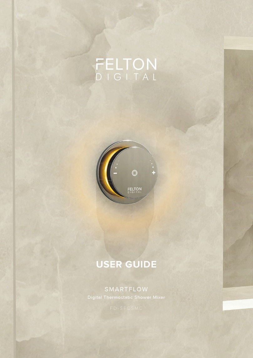
Felton Digital SMARTVIEW FD-SVCSMC User manual

1
FELTON DIGITAL
INSTALLATION GUIDE
SMARTVIEW™
Digital Thermostatic Shower Mixer
FD-SVCSMC

2
SMARTVIEW INSTALL GUIDE

3
FELTON DIGITAL
Vision wheel interface pre-line installation 8
Operational test 19
Notice 5
Measurements 5
Tools required 6
Scope of application 7
TLC 30 FTD installation 9
Vision wheel interface nal t installation 14
Troubleshooting 20
Warranty 21
Processor template 23
Scope of delivery 6
CONTENT

4
SMARTVIEW INSTALL GUIDE

5
FELTON DIGITAL
WATER PATH
Input 2 × 1/ 2˝ BSP female
Output 2 × 1 / 2˝ BSP female
Flow max. 36 l /min at 300kPa
Pressure range Min 150kPa - Max 500kPa
Dierence of pressure Max. 100 kPa/14.5psi
Maximum outlet temperature 45°C
Hot inlet temp range 55°C - 85°C
Cold inlet temp range 5°C - 25°C
ELECTRONICS
Power supply 100-240V AC / 50–60 Hz
Power consumption Standby < 0.5 W, max. 45 W
PLEASE READ THE MANUAL CAREFULLY BEFORE STARTING THE INSTALLATION. AFTER COMMISSIONING AND TESTING THE
SYSTEMS FUNCTIONALITY, THIS DOCUMENT MUST BE GIVEN TO THE END USER OF THE SYSTEM.
PRODUCT TO BE DISCONNECTED BEFORE LINE TEST
In case of a power cut, the unit will remain inactive until the power is back on.
GENERAL
This installation manual contains instructions for the correct installation of the Smartview™ product. The warranty will be invalidated if the
product is not installed according to these instructions.
Installation must be carried out by qualied installers in accordance to this installation manual. Country-specic standards, rules and safety
regulation do apply.
PLACE OF INSTALLATION
The Smartview™ product must be installed in an accessible place and in accordance to this installation manual. This ensures a problem-free
service and maintenance procedure.
DANGER OF ELECTRIC SHOCK!
ELECTRICAL INSTALLATION
Before opening the housing, the mains connection must be switched o. Work on electrical parts and connections must be carried out by
qualied electrician. Country-specic standards and regulations do apply.
PRECAUTIONS
1. This appliance is not intended for use by persons (including children) with reduced physical, sensory or mental capabilities, or lack of
experience and knowledge, unless they have been given supervision or instruction concerning use of the appliance by a person responsible
for their safety.
2. Children should be supervised to ensure that they do not play with the appliance.
3. If the supply cord is damaged, it must be replaced by the manufacturer, its service agent or similarly qualied persons in order to avoid a
hazard.
4. This appliance contains battery that are only replaceable by skilled persons.
5. An electronic copy of installation and user guides are available on Felton Digital website – please visit www.feltondigital.co.nz to view le.
MAINTENANCE
Felton Digital products are made of high quality materials and require only minimal maintenance. The following maintenance tips help to
preserve the surface and prevent damage through incorrect cleaning. Fittings and control parts should be wiped dry after used. Only use
mild cleaning products that contain soap. The following must not be used: Scourers, abrasive sponges, hydrochloric acid, lime-, plaster- or
cement removers, solutions or cleaning agents containing acid (pH ≤ 4), lime scale remover or vinegar-based cleaner – and cleaning agents
where the chemical solution is not known which may be sold as special cleaner for ttings.
NOTICE
TOOLS REQUIRED
5. Drill
3. Crosshead screwdriver 4. Spanner
2. Drill bit ø 8 mm
1. Pencil
6. 70mm holesaw 8. Spirit level
7. Utility knife

6
SMARTVIEW INSTALL GUIDE
BOX 1
TLC 30 FTD VISION SHOWER
BOX 2
VISION WHEEL INTERFACE
1. TLI-W body 3. In-wall box
5. Set of screws
6x2.5x16mm 6. TLI-W knob
1. TLC 30 FTD
3. Set of screws
2x5x50mm
2. Back Up Battery
4. Connecting adapter
2. Vision wheel
black/white
4. Fastening
& seal Kit
silicone seal
black
foam
seal
wall plug
steel clip
screws
250 mm
75 mm
256 mm
110mm
10 mm
43 mm
56mm
MEASUREMENTS

7
FELTON DIGITAL
A Ceiling Mounted Shower handset (Recommended)
B Wall Mounted Shower handset
Cable length
6m max.
Cold inHot in
Handset &
fixed head
outlets
Pipework in
Control cables
Pipework out
TLC 30 FTD
VISION WHEEL INTEFACE
Note: The vision wheel interface
can be fitted anywhere in the
showering area.
Important: The TLC 30 FTD
must be accessible and
should not be sealed in the
wall.
Cable length
6m max.
Hot inCold in
TLC 30 FTD
Handset & fixed
head outlets
VISION WHEEL INTEFACE
Note: The vision wheel interface
can be fitted anywhere in the
showering area.
Pipework in
Control cables
Pipework out
1
2
SCOPE OF APPLICATION
Warning
Please make sure the power source is
installed by a qualied electrician and
complies to Electrical standard/NZ laws.
Important: The TLC 30 FTD must have
an access panel.

8
SMARTVIEW INSTALL GUIDE
2Attaching the in-wall box
Prepare the wall to take the in-wall box. The installation of the in-wall box will depend on each individual
situation.
face of the timber framing. Conduits should be used in the walls where necessary to protect the cables and
allow maintenance. Attach the in-wall box using the screws supplied.
In-wall box attached
from the front
NOG
1 Cutting down the in-wall box (OPTIONAL)
NOTE: We recommend the in-wall box is cut down as shown using a hacksaw

9
FELTON DIGITAL
15V ACCU EXT RS-232 MOTOR TLI AUX
4Remove cover
TLC 30 FTD INSTALLATION
Wire (not supplied)
Conduit (not supplied)
The draw wire should be tted before the wall is lined.
NOTE: Feeding a string or wire through the in-wall box and conduit will make it easier to pull the cables
through to the TLC 30 FTD.
3Draw wire through in-wall box

10
SMARTVIEW INSTALL GUIDE
15V ACCU EXT RS-232 MOTOR TLI AUX
Outlet
HOT COLD
Inlets
Fixing holes
Cover
retaining
holes
Connector block
Power supply
Battery compartment
12
Connects to hand shower
1
Connects to xed head
2
5Inside TLC 30 FTD

11
FELTON DIGITAL
MOUNTING FOR NOG (RECOMMENDED)
6 Mark the position of the TLC 30 FTD xing holes in the selected location
Important: The location of the TLC
30 FTD must be acessible and dry.
Use the processor template on the
last page to mark the position of the
xing holes in the selected location.
ORIENTATION FOR WALL SITUATION:
MOUNTING OPTIONS
MOUNTING FOR CONCRETE
1Install TLC TLC 30 FTD 1 Drill xing holes
99 mm
56 mm
ø 5 mm / 0.2˝
2Install TLC 30 FTD
15V ACCU EXT RS-232 MOTOR TLI AUX
15V ACCU EXT RS-232 MOTOR TLI AUX

12
SMARTVIEW INSTALL GUIDE
15V ACCU EXT RS-232 MOTOR TLI AUX
9Tighten adapter retaining bolt
15V ACCU EXT RS-232 MOTOR TLI AUX
Fully insert the inlet adapter into the inlet valves (one long and one short adapter).
8Connect hot and cold water supply
IMPORTANT: Flush the
pipework before connection
A
B
Connect hot and cold water supply
Insert inlet supply
A
B
HOT
COLD
LONG
SHORT
7Remove inlet adapter retaining bolt
15V ACCU EXT RS-232 MOTOR TLI AUX

13
FELTON DIGITAL
15V ACCU EXT RS-232 MOTOR TLI AUX
1
2
LONG
SHORT
15V ACCU EXT RS-232 MOTOR TLI AUX
1
2
LONG
SHORT
Insert outlet adapters and connect outlet pipeworks
Primary outlet (Hand Shower)
Secondary outlet (Fixed Head)
1
2
If using two outlets:
Connect outlet and outlet
12
If only using single outlet:
Outlet to be connected.
Outlet to be plugged and sealed.
1
2
11 Connect outlet pipeworks
10 Remove outlet adapter retaining bolts
15V ACCU EXT RS-232 MOTOR TLI AUX

14
SMARTVIEW INSTALL GUIDE
13 Fit o after nal wall lining is installed
Finish the wall by tiling etc.
40mm diameter holes should be drilled in the tile etc to nish.
Draw a line around the collar, with the wall. Cut down the collar as marked.
Final wall lining Final wall lining
12 Tighten adapter retaining bolt
15V ACCU EXT RS-232 MOTOR TLI AUX
VISION WHEEL INTERFACE FINAL FIT INSTALLATION

15
FELTON DIGITAL
Fix the control steel clip to the wall where shown using the xings supplied.
Remove TLI-W knob from the TLI-W body. Feed data cable through silicone seal and black foam seal
Secure both cables to the previously installed draw wire and pull the cables to the TLC 30 FTD.
60 mm
ø 5 mm
40mm
56mm
60mm 110mm
Steel clip
A
D
C
C
D
B
14 Attach steel clip
15 Feed both cables through to TLC 30 FTD
A
Fit black foam seal
around groove
B

16
SMARTVIEW INSTALL GUIDE
17 Position TLI-W body into the vision wheel interface and lock by turning clockwise.
2
Fit knob
3
16 Position vision wheel interface and attach in screws
1Push and twist to lock
ADVICE: Push in rmly!
Fit silicone seal
inside the vision
wheel interface

17
FELTON DIGITAL
18 Connect back up battery
19 Connect TLI-W body to TLI port
15V ACCU EXT RS-232 MOTOR TLI AUX
TLI
15V ACCU EXT RS-232 MOTOR TLI AUX
15V ACCU EXT RS-232 MOTOR TLI AUX
15V ACCU EXT RS-232 MOTOR TLI AUX
Place back up battery in shown
location within TLC 30 FTD and
connect cable to ACCU port.
Note: After installation, battery
may require 24 hours of charging
on mains power before battery
back up function before fully
operational. Charging occurs once
unit is on mains power.
1
Plug the TLI-W
body cable to the
TLI port as shown
TLI-W BODY
GREY CABLE
15V ACCU EXT RS-232 MOTOR TLI AUX
15V ACCU EXT RS-232 MOTOR TLI AUX
15V ACCU EXT RS-232 MOTOR TLI AUX
15V ACCU EXT RS-232 MOTOR TLI AUX

18
SMARTVIEW INSTALL GUIDE
15V ACCU EXT RS-232 MOTOR TLI AUX
RS-232
15V ACCU EXT RS-232 MOTOR TLI AUX
15V ACCU EXT RS-232 MOTOR TLI AUX
15V ACCU EXT RS-232 MOTOR TLI AUX
15V ACCU EXT RS-232 MOTOR TLI AUX
IMPORTANT: Electrical supply must be
installed by a qualied electrician.
15V ACCU EXT RS-232 MOTOR TLI AUX
21 Re-t cover and connect TLC 30 FTD to the mains
20 Connect vision wheel interface to RS-232 port
Plug the vision wheel
interface to the RS-232
port as shown
1
RS-232 VISION WHEEL
BLACK CABLE

19
FELTON DIGITAL
OPERATIONAL TESTING:
1Ensure that the TLC 30 FTD is installed correctly and connected to the power supply.
The installed system should be operated to check for leaks.
2 Open
Push the Smartview™ Interface once.
The TLC 30 FTD unit opens and the LED illuminates.
3 Close
Push the Smartview™ Interface again.
The TLC 30 FTD unit closes and the LED goes o.
The installed system should be operated to check for leaks.

20
SMARTVIEW INSTALL GUIDE
SMARTVIEW™ TROUBLESHOOTING
If issue persists or not covered by the above troubleshooting, please contact our
ISSUE PROBLEM TROUBLESHOOT
The device does not function
(i.e. the LED light is not on)
The AC adapter is not connected
to the mains Connect device to the mains power
Mains power failure Check household fuse box
Back up battery not connected Follow Step 18 on Smartview Installation Guide
Vision wheel interface is not working Follow Step 19-20 on Smartview Installation
Guide
Device does not operate during a power
failure
Battery not connected Connect battery with controller (ACCU)
Battery at Charge for at least 24hours. Follow Step 18 on
Smartview Installation Guide
Battery defective Replace (replace every 3 to 5 years)
The water temperature does not match
the indicated display
Hot and cold water connections reversed Check connections are correct
Hot or cold water stop valve closed or only half
opened Fully open both stop valves
Kink in supply hose Check connection hoses
Connecting pipe blocked Flush pipes and clean lter
No hot water Check hot water tank and instantaneous
connections
Temperature sensor defect Carry out function «Self Check Diagnosis»
on Smartview User Guide
Dierence in supply pressure
between hot and cold water greater than 100kPa Balance pressure to eliminate dierence
Unit will not turn o Carry out function «Self Check Diagnosis»
on Smartview User Guide
time has been reached Flow sensor is defective Carry out function «Self Check Diagnosis»
on Smartview User Guide
The device is working but has
Motors are not calibrated Carry out function «Self Check Diagnosis»
On Smartview User Guide
Stop valves closed Open stop valves fully
No water supply Restore water supply
Kink in supply hose Check connection hoses
Cleaning mode active Wait 45 seconds or deactivate
via menu
The TLC 30 FTD is damp or wet Inlet and outlets of TLC 30 FTD are not properly
sealed Inspect all connections, reseal if necessary
The vision wheel interface does not
adjustment
The interface elements
are connected incorrectly
Follow Step 19-20 on Smartview Installation
Guide
The interface is defective Carry out function «Self Check Diagnosis»
On Smartview User Guide
The knob is not running smoothly Remove and clean knob
Other manuals for SMARTVIEW FD-SVCSMC
1
Table of contents
Other Felton Digital Plumbing Product manuals
