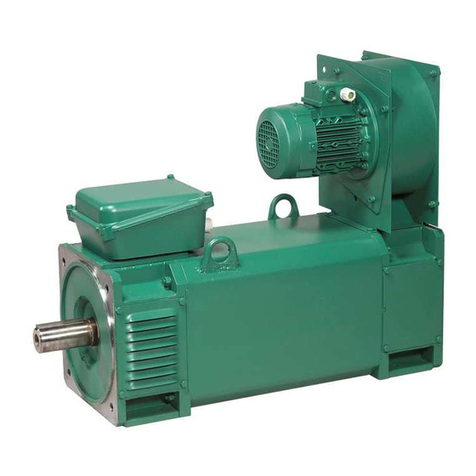
Fenner K Series Manual

www.fptgroup.com
Fenner is a registered Trade Mark of Fenner PLC
All Dimensions are in Millimetres unless otherwise stated
Head Office: Amber Way, Halesowen,West Midlands. B62 8WG
w w w . f p t g r o u p . c o m
SERIES K
GEARMOTORS
Installation and Maintenance
RECOMMENDED OIL GRADES
4
IMPORTANT HEALTH & SAFETY
INSTALLATION LEAFLETS
Satisfactory performance depends on proper installation, lubrication
and maintenance. All instructions given in the installation leaflet must
be followed carefully.
LUBRICATION
Sizes 890 to 893 will be supplied with a quantity of EP mineral oil
(Shell Omala 320) for mounting position B3. Other mounting must
be specified on order. However if , as requested, the unit is sup-
plied without lubricant then the oil quantity is obtained from Tables
1 & 2. Sizes 894 to 898 are supplied without oil. Before running
they should be filled with an appropriate amount of the correct
lubricant shown in the tables 1 & 2, dependent on the mounting
position, see below.
WARNING Do not overfill as excess lubricant may cause over-
heating and leakage.
OIL CHANGES
Sizes 890, 891 and 892 are lubricated for life except when
the units are required to work in an explosive atmosphere
(94/9/EC Atex 100a Group II category 2 zones 1 & 21 & category
3 zones 2 & 22) See separate leaflet for recommendations.
All other sizes will require an oil change depending on the unit
operating temperature. Initial fill of oil should be changed in a new
gear unit after 1000 hours operation or one year or half the life in
the table opposite whichever is the soonest.
PERIODIC INSPECTION
Check oil level every 3000 hours or 6 months whichever is sooner
on sizes 893 to 898 and if necessary top up with the recommend-
ed grade of lubricant.
TABLE 2. LUBRICANT QUANTITY (LITRES)
QUINTUPLE REDUCTION
Mounting Position
Unit B3 V5 V6 B8 B7 B6
Size Primary Secondary Primary Secondary Primary Secondary Primary Secondary Primary Secondary Primary Secondary
890 0.7 0.8 0.7 1.0 0.7 1.0 0.7 1.3 1.0 1.7 1.1 1.0
891 0.7 1.0 0.7 1.3 0.7 1.3 0.7 1.7 1.0 2.1 1.1 1.3
892 0.8 1.5 0.8 1.85 0.8 1.85 0.8 2.4 1.4 3.1 1.5 1.9
893 0.8 1.7 0.8 2.8 0.8 2.8 0.8 3.3 1.4 4.2 1.5 2.9
894 0.8 3.5 0.8 5.8 0.8 5.8 0.8 9.1 1.4 10.4 1.5 9.1
895 1.6 4.5 1.6 9.3 1.6 6.2 1.6 9.1 1.9 10.4 2.5 9.1
896 1.6 8.8 1.6 15.0 1.6 15.0 1.6 17.5 1.9 20.9 2.5 16.3
897 2.8 14.0 2.8 24.0 2.8 24.0 2.8 28.6 3.2 33.0 4.9 25.6
898 2.8 22.0 2.8 36.0 2.8 36.0 2.8 41.0 3.2 49.0 4.9 35.9
Primary units are filled with Shell Omala 320 and are suitable for all ambient temperatures between 0 and 35 C.
TABLE 1. LUBRICANT QUANTITY (LITRES)
TRIPLE REDUCTION
890, 891 & 892 - fill with the correct quantity of lubricant.
893 to 898 - fill gearbox until oil escapes from level plug
Unit Mounting Position
Size B3 B6 B7 B8 V5 V6
890 0.8 1.0 1.7 1.3 1.0 1.0
891 1.0 1.3 2.2 1.7 1.3 1.3
892 1.5 1.9 3.1 2.4 1.85 1.9
893 1.7 2.9 4.2 3.3 2.8 2.8
894 3.5 5.8 8.7 6.8 5.8 5.8
895 4.5 9.1 10.5 9.1 8.0 8.0
896 8.8 16.3 21 17.5 15 15
897 14 25.5 33 28.6 24 2
898 22.0 36 49 41 36 36.0
All Quantities are approximate.
LUBRICANT TYPE TEMPERATURE RANGE
ISO Ambient Temperature °C
Viscosity -5°C to 20°C -30°C to 20°C 0°C to 35°C 20°C to 50°C
EP Mineral Oil 220 - 320 460
Synthetic Oil 1 - 220 220 320
Synthetic Oil 2 - 220 320 460
Synthetic Oil 1 = Polyalphaolein based.
Synthetic Oil 2 = Polyglycol basrd
Supplier Mineral Oils Containing Synthetic Lubricants Synthetic Lubricants
EP Additives Polyglycol Based Polyalphaolefin based
BP Energol GR-XP or XF Enersyn SG-XP Enersyn EPX
Castrol Alpha Max or SP Alphasyn PG Alphasyn EP or T
Esso Spartan EP Glycolube Spartan Synthetic EP
Fuchs Renogear V or WE Renolin PG Renogear SG
Mobil Mobilgear 600 Glygoyle Mobilgear SHC
Shell Omala or Omala F Tivela or Tivela S Omala HD
Texaco Meropa or Meropa WM Synlube CLP Pinnacle EP
Total Carter EP Carter SY Carter EP/HT
Rocol Sapphire Hi-Torque - -
Unit Operating Renewal Period (Hours)
Temp C Mineral Oil Synthetic Oil
75 or less 17000 or 3 Yrs 26000 or 3 Yrs
80 12000 or 3 Yrs 26000 or 3 Yrs
85 8500 or 3 Yrs 21000 or 3 Yrs
90 6000 or 2 Yrs 15000 or 3 Yrs
95 4200 or 17 Mths 10500 or 3 Yrs
100 3000 or 12 Mths 7500 or 2.5 Yrs
105 2100 or 8 Mths 6200 or 2 Yrs
110 1500 or 6 Mths 2100 or 18 Mths
OIL RENEWAL TABLE

www.fptgroup.com
Fenner is a registered Trade Mark of Fenner PLC
All Dimensions are in Millimetres unless otherwise stated
Head Office: Amber Way, Halesowen,West Midlands. B62 8WG
w w w . f p t g r o u p . c o m
SERIES K
GEARMOTORS
Installation and Maintenance 4
MOUNTING POSITIONS
Plug positions apply for sizes 893 and larger.
Ventilator/Filling Position Level Position Drain Position
SHAFT MOUNTING
Ensure that the shaft on to which the gear unit is to be mounted
and the gear unit bore are clean and free from burrs.
Liberally smear the shaft and bore with lubricants to aid
assembly and prevent fretting corrosion. Slide the unit on to the
driven shaft. Fit side fitting key. DO NOT USE TAPER OR TOP
FITTING KEY.
FOOT OR FLANGE MOUNTING
The Fenner series K is designed primarily as a shaft mounted
gearbox, however if a customer wishes to use the unit in the foot
mounted position all sizes have pre-cast feet built in to the gearcase
for mounting in the B3 position. Series K can also be used as a
flange mounted unit, standard output flanges area available as acces-
sories. Consult you local Authorised Distributor for details. Use the
tightening torques listed below for holding down bolts.
Clean shaft extensions and ventilator where fitted
The shafts of the unit and driven equipment should be in as perfect
alignment as possible. Fenaflex®couplings should be used when
shaft alignment cannot be assured and also when protection from
peak and vibrating torques are desirable. Ensure the base foundation/
flange mounting surface is flat*, vibration and torsionally rigid.
The drive should be mounted on a rigid support and bolted down
firmly using set screws to ISO grade 8.8 minimum. Ensure that ma-
chined mounting points are supported over their full area. If packing
is to be used, place either side of the mounting bolt. During the final
bolting down ensure the unit and/or baseplate are not distorted to
maximise unit performance.
For units mounted on bedplates, dowel two diagonally opposite feet
in to position.
Fit all guards required to comply with the factory acts, check the mo-
tor wiring for correct direction of rotation and check oil levels.
*Maximum permissible flatness error for mounting surface is 0.12mm.
MOTOR CONNECTIONS TO MAINS
Connection of the electric motor to the mains supply should be
made by a qualified person.The current rating of the motor will be
identified on the motor plate and correct sizing of the cables to
electrical regulations is essential.
STARTING UP
Prior to starting up the following procedure should be followed
1. Ensure Ventilator is fitted ( size 893 and above
2. Check Oil level (893 and above) top up if necessary
3. Ensure all safety devices are in place (i.e. guards fitted)
4. Remove any safety devices fitted to prevent machine rotation
Starting up should be performed or supervised by suitably quali-
fied personnel.
BREATHERS/MOUNTING POSITIONS
Sizes 890,891 & 892 are supplied for operation without breathers.
Size 893 is supplied for operation with a breather but to prevent
leakage during transit this unit is fitted with blanking plugs. It
is essential that when the unit is in its operating position the
relevant blanking plug is removed and replaced by the breather
plug (supplied) in the position indicated on the installation leaflet.
Sizes 894 to 898 are supplied for operation with a breather but are
despatched without oil.
It is essential that when the unit is in its operating position the
relevant blanking plug is removed and replaced by the breather
plug (supplied) in the position indicated on the installation leaflet.
1. Ensure Ventilator is fitted (size 893 and above)
2. Check Oil level (893 and above) top up if necessary
3. Ensure all safety devices are in place (i.e. guards fitted)
4. Remove any safety devices fitted to prevent machine rotation
Starting up should be performed or supervised by suitably quali-
fied personnel.
Ceiling Mounted (B8)
Left Hand Wall Mounting (B6)
Vertical Mounting Shaft Up (V6) Flange Mounting Shaft Up (V3)
Vertical Mounting Shaft Down (V5) Shaft Down Flange Mounting (V1)
Right Hand Wall Mounting (B7)
Standard Floor Mounted (B3)
Set Screw Foot & Output Motors to
Size Flange Bolts Gearhead
Torque (Nm)
M6 10 10
M8 25 18
M10 50 37
M12 85 64
M16 200 150
M20 350 260
M24 610 -
M30 1220 -
M36 2150 -

SERIES K - GEARBOXES
8
284 Drive Design & Maintenance Manual - FEN01/10
Dimensions Motorised
SIZE a a2 a3 b b0 c e f f0 h h1 k n n0 o
890 100 28 32 110 115 11 120 143 152 100 16 38 38 60
891 120 35 37 130 130 16 145 168 171 112 13 38 40 75
892 130 30 45 130 150 15 157 170 192 132 5 40 40 83
893 140 30 45 120 160 20 170 176 208 140 13 For k 55 48 90
894 165 40 55 150 200 27 200 210 263 180 25 dimensions 60 55 105
895 180 55 70 180 233 30 230 256 309 212 15 see facing 76 76 120
896 240 75 75 240 295 35 290 340 395 265 10 page 100 100 150
897 270 95 95 280 360 40 340 390 455 315 41 110 115 175
898 330 115 110 350 420 45 400 470 540 375 65 120 120 205
SIZE p3 q q1 s v2 v4 w7 y z D m m1 m2 m3 T U v3
890 167 63 159 11 76 - 63 140 0.0 30 52.5 120 105 30.3 33.5 8 M10X50L
891 187 71 179 11 76 - 78 140 2.5 35 66.0 150 132 35.3 38.5 10 M12X55L
892 217 80 219 14 91 - 87 180 4.5 40 73.0 166 142 40.3 43.5 12 M16X70L
893 233 90 229 14 91 - 94 180 5.0 40 80.0 180 156 40.3 43.5 12 M16X70L
894 288 112 265 18 91 - 109 212 5.0 50 92.5 210 183 50.5 54.0 14 M16X70L
895 341 132 330 23 115 - 124 250 5.0 60 105.0 240 210 60.5 64.5 18 M20X80L
896 420 160 355 27 115 - 154 300 5.0 70 132.5 300 270 70.5 75.0 20 M20X80L
897 513 200 423 34 140 155 180 360 5.0 80 155.0 350 313 80.5 85.5 22 M20X80L
898 590 225 476 39 140 155 210 400 5.0 100 180.0 410 373 100.5 106.5 28 M24X110L
TRIPLE REDUCTION
QUINTUPLE REDUCTION
* for motor dimensions
see page 307
* for motor dimensions
see page 307

Section
SERIES K - GEARBOXES
8
GEARBOXES
FEN01/10 - Drive Design & Maintenance Manual 285
Dimensions Motorised
Motor Frame Dimension k
Size 890 891 892 893 894 895 896 897 898
63 442 470 535 555 614 728 789
71 446 474 539 559 618 731 795
80A 459 487 552 572 631 749 813 952 1078
90S 469 497 562 582 641 759 823 962 1088
100L 458 486 551 571 630 786 850 973 1099
112M 458 486 551 571 630 786 850 973 1099
132SA 785 849 996 1122
160M 1004 1130
Motor Frame Dimension k
Size 890 891 892 893 894 895 896 897 898
63 256 284 311 331
71 260 288 317 337
80 273 301 335 355 414 506 570
90 283 311 345 365 424 509 573
100 246 300 372 392 435 515 579 670 796
112 231 300 372 392 435 515 579 670 796
132 372 391 458 515 579 670 796
160 466 545 614 705 789
180 614 705 789
200 614 705 789
225 641 732 816
250 988
280 988
TRIPLE REDUCTION DIMENSIONS
QUINTUPLE REDUCTION DIMENSIONS

Section
SERIES K - GEARBOXES
8
GEARBOXES
FEN01/10 - Drive Design & Maintenance Manual 299
Extended Output Shaft *
SIZE Ø d i2 L L11 L12 o t u v
890 25.015 / 25.002 50 50 3 40 134.0 28.0 8 M10 x 1.5, 22 Deep
891 30.015 / 30.002 60 60 3 50 175.0 33.0 8 M12 x 1.75, 28 Deep
892 35.018 / 35.002 70 70 3 60 176.0 38.0 10 M16 x 2, 36 Deep
893 40.018 / 40.002 80 80 3 70 210.0 43.0 12 M16 x 2, 36 Deep
894 50.018 / 50.002 100 100 3 80 242.0 53.5 14 M16 x 2, 36 Deep
895 60.030 / 60.011 120 120 3 100 285.0 64.0 18 M20 x 2.5, 42 Deep
896 70.030 / 70.011 140 140 3 110 341.0 74.5 20 M20 x 2.5, 42 Deep
897 90.035 / 90.013 170 170 5 140 405.5 95.0 25 M20 x 2.5, 42 Deep
898 110.035 / 110.013 210 210 5 180 475.5 116.0 28 M24 x 3, 55 Deep
* It is recommended that when using a B5 output flange and output shaft, the extended version is used
SIZE Øa1 a4 Øb1 c1 Øe1 f1 h M Øs1
890 160 144.0 110 j6 10 130 3.5 100 45° 9
891 200 190.0 130 j6 12 165 3.5 112 45° 11
892 250 189.0 180 j6 16 215 4.0 132 45° 14
893 250 220.0 180 j6 18 215 4.0 140 45° 14
894 300 247.0 230 j6 18 265 4.0 180 45° 14
895 350 285.0 250 h6 18 300 5.0 212 45° 18
896 450 351.0 350 h6 20 400 5.0 265 22.5° 18
897 450 410.5 350 h6 22 400 5.0 315 22.5° 18
898 450 470.5 350 h6 22 400 5.0 375 22.5° 18
øe1
M
8 Holes
s1 dia
a4
h
B5 Output Flange on Left
u
f1
i2
c1
o
øb1
øa1
L
L12 L11
B5 Output Flange on Right
Tapped Hole
v
t
ød
u
Output Shaft
SIZES 890 TO 895
SIZES 896 TO 899
B5 FLANGE DIMENSIONS
øe1
M
4 Holes
s1 dia
B5 FLANGE DIMENSIONS
EXTENDED OUTPUT SHAFT DIMENSIONS
Accessories

SERIES K - GEARBOXES
8
300 Drive Design & Maintenance Manual - FEN01/10
Unit Single Extension Double Extension Single Extension * B5 Output Torque
Size Output Shaft Output Shaft Extended Output Shaft Flange Arm
890 890A9700 890A9800 890A9900 871A9900 890A9600
891 891A9700 891A9800 891A9900 872A9900 891A9600
892 892A9700 892A9800 892A9900 892A9300 892A9600
893 893A9700 893A9800 893A9900 893A9300 893A9600
894 894A9700 894A9800 894A9900 894A9300 894A9600
895 883A9700 895A9800 895A9900 875A9900 895A9600
896 884A9700 896A9800 896A9900 876A9900 896A9600
897 885A9700 897A9800 897A9900 877A9900 897A9600
898 898A9700 898A9800 898A9900 877A9900 898A9600
øQ
øe5
F7
22. 5o
22.5 o
22.5 o
22.5 o
22.5 o
22. 5o
f F
o2 o2
ør
øR
Male spigot
890 - 894
Female recess
895 - 898
B14 FLANGE DIMENSIONS
890, 891 & 895
øe5
øQ
30o
30o
30o
30o
892
ACCESSORY PRODUCT CODES
Size Øe5 F7 o2 Q Ør h7 ØR H7 Spigot f Recess F
SPIGOT Ø
890 107 PCD 6 HOLES M8 X 1.25, 12 DEEP 55 122 85 - 2.5 -
891 130 PCD 6 HOLES M8 X 1.25, 12 DEEP 70 146 105 - 2.5 -
892 125 PCD 6 HOLES M10 X 1.5, 17 DEEP 75 150 105 - 3.0 -
893 150 PCD 6 HOLES M10 X 1.5, 17 DEEP 83 180 130 - 3.5 -
894 150 PCD 8 HOLES M10 X 1.5, 17 DEEP 95 180 130 - 6.0 -
895 195 PCD 6 HOLES M12 X 1.75, 20 DEEP 115 220 - 150 - 5
896 230 PCD 5 HOLES M16 X 2.0, 27 DEEP 145 260 - 180 - 6
897 280 PCD 8 HOLES M16 X 2.0, 27 DEEP 170 310 - 210 - 7
898 280 PCD 9 HOLES M16 X 2.0, 27 DEEP 200 310 - 210 - 7
øe5
øQ
45o
45o
893
øe5
øQ
45o
45o
45o
45o
894
øe5
øQ
30o
30o
30o
30o
896
øe5
øQ
36o
36o
36o
18o
18o
18o
18o
897
øe5
øQ
36o
36o
36o
18o
18o
18o
18o
898
* For use with B5 Output flange
Accessories

SERIES K - GEARBOXES
8
294 Drive Design & Maintenance Manual - FEN01/10
SIZE a a2 a3 b b0 c e f f0 g2* h h1 k* n n0 o p3 q q1 T2* s w7 z
890 100 28 32 110 115 11 120 143 152 140 100 16 333 38 38 60 167 63 159 111 11 63 0.0
891 120 35 37 130 130 16 145 168 171 140 112 13 361 38 40 75 187 71 179 111 11 78 2.5
892 130 30 45 130 150 15 157 170 192 180 132 5 410 40 40 83 217 80 219 111 14 87 4.5
893 140 30 45 120 160 20 170 176 208 180 140 13 430 55 48 90 233 90 229 111 14 94 5.0
894 165 40 55 150 200 27 200 210 263 212 180 25 492 60 55 105 288 112 265 115 18 109 5.0
895 180 55 70 180 233 30 230 256 309 250 212 15 622 76 76 120 341 132 330 160 23 124 5.0
896 240 75 75 240 295 35 290 340 395 300 265 10 710 100 100 150 420 160 355 195 27 154 5.0
897 270 95 95 280 360 40 340 390 455 360 315 41 856 110 115 175 513 200 423 233 34 180 5.0
898 330 115 110 350 420 45 400 470 540 400 375 65 987 120 120 205 590 225 476 286 39 210 5.0
*Dimensions relate to triple reduction, see quintuple reduction table on facing page for quintuple reduction dimensions
TRIPLE REDUCTION
QUINTUPLE REDUCTION
Non Motorised Dimensions

SERIES K - GEARBOXES
8
302 Drive Design & Maintenance Manual - FEN01/10
Satisfactory performance depends on proper
installation, lubrication and maintenance. All
instructions given in the installation leaflet
must be followed carefully.
Shaft Mounting
Ensure that the shaft on to which the gear
unit is to be mounted and the gear unit
bore are clean and free from burrs.
Liberally smear the shaft and bore with
lubricants to aid assembly and prevent
fretting corrosion. Slide the unit on to the
driven shaft. Fit side fitting key. DO NOT
USE TAPER OR TOP FITTING KEY.
Foot Mounting
Mount the unit securely to a rigid struc-
ture. Fit the output extension shaft as
required. Use flexible couplings such as
Fenaflex for shaft to shaft connections and
ensure that shaft misalignment is within
the coupling's capacity. When a pulley or
sprocket is fitted to either shaft, mount it
as close as possible to the gearcase.
When fitting or removing drive compo-
nents do not hammer on shaft as this will
damage the bearings, Fenner Taper Lock
bushes permit easy fixing and dismantling
without undue force.
LUBRICATION
Sizes 890 to 893 will be supplied with a
quantity of EP mineral oil (Shell Omala 320)
for mounting position B3. Other mountings
must be specified on order. However if ,
as requested, the unit is supplied without
lubricant then the oil quantity is obtained
from Tables 1 & 2. Sizes 894 to 898 are
supplied without oil. Before running they
should be filled with an appropriate amount
of the correct lubricant shown in tables 1
& 2, dependent on the mounting position,
see below.
WARNING Do not overfill as excess lubri-
cant may cause overheating and leakage.
Oil Changes
Sizes 890, 891 and 892 are lubricated for
life except when the units are required to
work in an explosive atmosphere. (94/9/EC
Atex 100a Group II category 2 zones 1 &21
& category 3 zones 2 & 22). See separate
leaflet for recommendations. All other sizes
will require an oil change depending on the
unit operating temperature. Initial fill of oil
should be changed in a new gear unit after
1000 hours operation or one year or half
the life in the table below whichever is the
soonest.
Temperature Limitations
The standard lubricant is suitable for opera-
tion in ambient temperatures of 0 to 35°C,
outside of this consult your local Author-
ised Distributor.
BREATHERS/MOUNTING POSITIONS
Sizes 890,891 & 892 are supplied for op-
eration without breathers.
Size 893 is supplied for operation with a
breather but to prevent leakage during
transit this unit is fitted with blanking plugs.
It is essential that when the unit is in its op-
erating position the relevant blanking plug
is removed and replaced by the breather
plug (supplied) in the position indicated on
the installation leaflet.
Sizes 894 to 898 are supplied for operation
with a breather but are despatched without oil.
It is essential that when the unit is in its op-
erating position the relevant blanking plug
is removed and replaced by the breather
plug (supplied) in the position indicated on
the installation leaflet.
STARTING UP
Prior to starting up the following procedure
should be followed
Ensure Ventilator is fitted (size 893 and
1.
above)
Check Oil level (893 and above) top up
2.
if necessary
Ensure all safety devices are in place
3.
(i.e. guards fitted)
Remove any safety devices fitted to
4.
prevent machine rotation
Starting up should be performed or super-
vised by suitably qualified personnel.
MOUNTING POSITIONS
Plug positions apply for sizes 893 and larger. Ventilator/Filling Position Level Position Drain Position
Installation and Maintenance
Ceiling Mounted (B8)
Standard Floor Mounted (B3)
Right Hand Wall Mounting (B7) Left Hand Wall Mounting (B6)
Vertical Mounting Shaft Up (V6) Flange Mounting Shaft Up (V3) Vertical Mounting Shaft Down (V5) Shaft Down Flange Mounting (V1)
Unit Op Renewal Period (Hours)
Temp °C Mineral Oil Synthetic Oil
75 or less 17000 or 3 yrs 26000 or 3 yrs
80 12000 or 3 yrs 26000 or 3 yrs
85 8500 or 3 yrs 21000 or 3 yrs
90 6000 or 2 yrs 15000 or 3 yrs
95 4200 or 17 mths 10500 or 3 yrs
100 3000 or 12 mths 7500 or 2.5 yrs
105 2100 or 8 mths 6200 or 2 yrs
110 1500 or 6 mths 2100 or 18 mths
† † *
† Gear units for use in mounting
positions B6 and B7 should only be
selected with overall ratios greater than
or equal to those shown in the table
below.
* Mounting positions B6 are not
recommended for geared motors.
Please consult your local authorised
distributor.
Input Speed (rpm)
Unit Size 1000 1500 1800 >1800
890-895 All All All
896 All 11:1 14:1
897 11:1 20:1 25:1
898 16:1 32:1 36:1
Consult you local
distributor

Section
SERIES K - GEARBOXES
8
GEARBOXES
FEN01/10 - Drive Design & Maintenance Manual 303
LUBRICANT TYPE TEMPERATURE RANGE
Mounting Position
Unit B3 V5/V1 V6/V3 B8 B7 B6
Size Primary Secondary Primary Secondary Primary Secondary Primary Secondary Primary Secondary Primary Secondary
890 0.5 0.5 0.6 0.7 0.8 0.8 0.8 1.0 0.7 1.2 1.0 0.9
891 0.5 0.7 0.6 0.9 0.8 1.1 0.8 1.3 0.7 1.7 1.0 1.2
892 0.8 1.1 0.7 1.5 1.2 1.7 1.2 1.9 1.1 2.5 1.4 2.0
893 0.8 1.5 0.7 1.8 1.2 2.8 1.2 2.7 1.1 3.6 1.4 2.6
894 0.8 2.7 0.7 3.6 1.2 4.0 1.2 4.5 1.1 5.7 1.4 4.5
895 1.5 4.4 1.6 3.7 1.8 7.6 1.8 7.5 2.0 9.6 2.6 7.6
896 1.5 9.3 1.6 8.3 1.8 18.0 1.8 17.0 2.0 21.0 2.6 16.0
897 2.6 15.0 2.7 15.0 2.9 28.0 3.0 30.0 3.2 34.0 4.7 24.0
898 2.6 23.0 2.7 27.0 2.9 33.0 3.0 39.0 3.2 50.0 4.7 35.0
Unit Mounting Position
Size B3 V6/V3 V5/V1 B8 B7 B6
890 0.5 0.8 0.7 1.0 1.2 0.9
891 0.7 1.1 0.9 1.3 1.7 1.2
892 1.1 1.7 1.5 1.9 2.5 2.0
893 1.5 2.8 1.8 2.7 3.6 2.6
894 2.7 4.0 3.6 4.5 5.7 4.5
895 4.4 7.6 3.7 7.5 9.6 7.6
896 9.3 18.0 8.3 17.0 21.0 16.0
897 15.0 28.0 15.0 30.0 34.0 24.0
898 23.0 33.0 27.0 39.0 50.0 35.0
TABLE 1 LUBRICATION QUANTITY (LITRES) TRIPLE REDUCTION
TABLE 2 LUBRICATION QUANTITY (LITRES) QUINTUPLE REDUCTION
890, 891 & 892 if supplied without lubricant, fill with the correct amount as indicated in
the table below. 893 - 898 - fill gearbox until oil escapes from level plug.
Installation and Maintenance
ISO Ambient Temperature °C
Viscosity -5°C to 20°C -30°C to 20°C 0°C to 35°C 20°C to 50°C
EP Mineral Oil 220 - 320 460
Synthetic Oil 1 - 220 220 320
Synthetic Oil 2 - 220 320 460
Synthetic Oil 1 = Polyalphaolein based.
Synthetic Oil 2 = Polyglycol basrd
Supplier Mineral Oils Containing EP Synthetic Lubricants Synthetic Lubricants
Additives Polyglycol Based Polyalphaolefin based
BP Energol GR-XP or XF Enersyn SG-XP Enersyn EPX
Castrol Alpha Max or SP Alphasyn PG Alphasyn EP or T
Esso Spartan EP Glycolube Spartan Synthetic EP
Fuchs Renogear V or WE Renolin PG Renogear SG
Mobil Mobilgear 600 Glygoyle Mobilgear SHC
Shell Omala or Omala F Tivela or Tivela S Omala HD
Texaco Meropa or Meropa WM Synlube CLP Pinnacle EP
Total Carter EP Carter SY Carter EP/HT
Rocol Sapphire Hi-Torque - -
RECOMMENDED OIL GRADES

Table of contents
