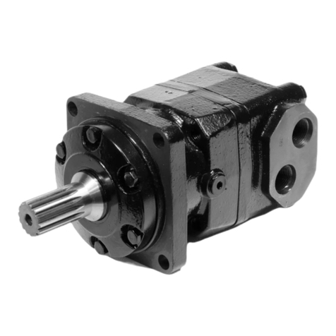
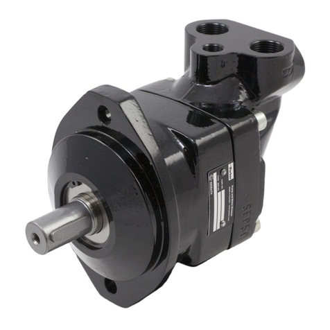
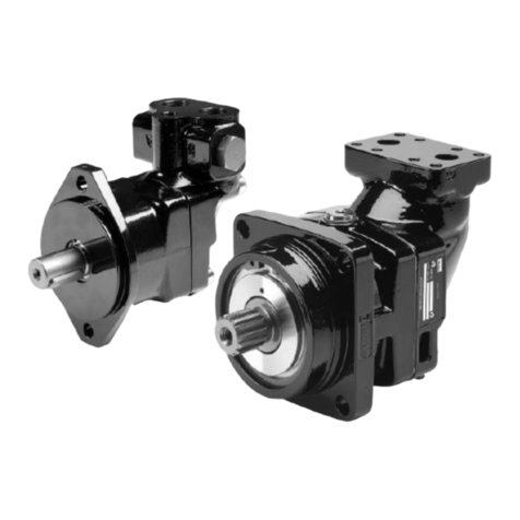
Service/Spare Parts Manual
Series V16
MSG30-5526-M1/UK
11 Parker Hannifin
Pump & Motor Division Europe
Trollhättan, Sweden
Parker Hannifin
Pump & Motor Division Europe
Trollhättan, Sweden
Ordering Code
Ordering Code
1. Frame size
220 – 220 cm³/rev
270 – 270 cm³/rev
2. Function
M– Negative control characteristics.
Motor starts in max displacement, std. for
EO, EP, HO, HP.
T– Positive control characteristics.
Motor starts in min displacement, std. for
AC; optional for EO, EP, HO, HP
3. Mounting flange & ports
I– ISO version
S– SAE version
4. Main ports
00– Axial and radial ports
AA– Axial ports
RR – Radial ports
AR– Axial port on A-side
Radial port on B-side
RA– Radial port on A-side
Axial port on B-side
A0– Axial port on A-side,
Radial and axial port on B-side
0A– Radial and axial port on A-side
Axial port on B-side
R0– Radial port on A-side
Radial and axial port on B-side
0R– Radial and axial port on A-side
Radial port on B-side
5. Shaft end
D (std.) – V16-220: DIN spline W50
V16-270: DIN spline W60
Z (option) – V16-270: DIN spline W50
S (std.) – V16-220: SAE spline 2” T15
V16-270: SAE spline 2,25” T17
U (option) – V16-270: SAE spline 2” T15
H (option) – V16-270: SAE spline 2,25” T17 ”long”
6. Control
AC– Pressure compensator
EO – Electro hydraulic, two-position
EP– Electro hydraulic, proportional
HO – Hydraulic, two position
HP– Hydraulic, proportional
7. Control signal
A– Pressure cut o, EO, EP, 12 VDC
B– Pressure cut o, EO, EP 24 VDC
C– Pressure cut o, HO, HP
E– External pressure (AC, HO, HP)
I– Internal pressure (AC)
L– 12 VDC (EO, EP)
H – 24 VDC (EO, EP)
D – 24 VDC ATEX-version (EO, EP)
Example: V16 - 220 - T - S AA S - AC E 3 B -P 420 - DT - 000 - 220 / 054 - 200 / 070 - 250 - 000 - 0
8. Control orifice set (orifice diameter in mm)
1– 0,6
2– 0,8
3– 1,0 (standard)
4– 1,2
5– EOA/EPA/EOB/EPB/HOC/HPC
X – Special
9. Control modulating (pressure/current)
N– AC, EO, HO: 0 [bar]
EPL, EOA, EPA 12 VDC: 900 [mA]
EPH, EOB, EPB 24 VDC: 450 [mA]
A– 15 [bar] (AC, HP, HPC)
B– 25 [bar] (AC, HP, HPC)
C– 35 [bar] (AC, HP, HPC)
D– 50 [bar] (AC)
E– 100 [bar] (AC)
10. Valve options
N– None
B – Brake valve and pressure relief valves
P – Pressure relief valves
L – Flushing valve two-sided
C – Flushing valve one-sided, Flushing from A side
D – Flushing valve one-sided, Flushing from B side
11. Pressure relief valve opening pressure /
Flushing valve orifice
000 – No valves (N)
XXX – Pressure setting of cartridge valve [bar]
0XX – Flushing valve orifice
12. Optional
00 – None
S0 – Speed sensor NPN
H0 – Speed sensor PNP
P0 – Position sensor
D0 – Speed sensor NPN + Poistion sensor
B0 – Speed sensor PNP + Position sensor
0T – Painted black
0X – Optional painting
13. Version number
XXX – Factory assigned (000 = std.)
14. Max. displacement internal [cm3/rev]
XXX – [cm3/rev] Non-adjustable
15. Min. displacement internal [cm3/rev]
XXX – [cm3/rev] Non-adjustable
16. Max. displacement external
XXX – [cm3/rev] Adjustable ≤ internal limitation
17. Min. displacement external
XXX – [cm3/rev] Adjustable ≥ internal limitation
18. Threshold pressure/current
XXX – [bar] alt. [mA]
19. Pressure cut o EOA/EOB/EPA/EPB/HOC/HPC
XXX – [bar] (000 = without pressure cut o)
20. Seal/protection cap on adjustement screws
0 – Standard seal cap in plastic
S – Protection cap in steel
2019181716151413121110987654321