Fenwal FLS-02EC User manual

ES1666 K10
Instruction Manual &
Technical Bulletin of
Explosion-proof Photoelectric Smoke Detector
FLS-02EC(-H2)
Thank you very much for purchasing. This
Instruction manual contains the important points in
preventing accidents and how to handle it. Please do
read thoroughly and comprehend this manual.
After reading it, please keep it in a convenient place
for reference.

1/13
ES1666
Contents
1. OVERVIEW ................................................................................................................................ 3
2. FEATURE................................................................................................................................... 3
3. SPECIFICATION ....................................................................................................................... 3
4. STRUCTURE.............................................................................................................................. 4
5. OPERATION .............................................................................................................................. 5
5.1. Status LED ............................................................................................................................. 5
5.2. Relay ....................................................................................................................................... 5
5.3. Automatic Test Function......................................................................................................... 5
6. INSTALLATION......................................................................................................................... 5
6.1. Installation Environments...................................................................................................... 6
6.2. Mounting................................................................................................................................. 6
6.3. Wiring ..................................................................................................................................... 7
6.3.1. Specification .................................................................................................................... 7
6.3.2. Procedure......................................................................................................................... 7
7. MAINTENANCE AND INSPECTION ......................................................................................10
8. ORDERING INFORMATION....................................................................................................11
9. CONTACT US............................................................................................................................11

2/13
ES1666
Warranty Period and Warranty Scope
【Warranty Period】
Warranty of the product is valid for only malfunctions occurring in the course of normal and correct
use of the product as per the Instructions Manual, and warranty period is 1 (one) year after the
product is delivered to the consignee specified at the time of order placement.
【Warranty Scope】
For the malfunctions occurring in the product due to reasons attributable to the supplier in the
aforementioned warranty period, supplier will repair the returned product at its own responsibility.
However, the following cases are excluded from the warranty scope.
1. Malfunctions and loss due to fire, earthquake, flood, lightning, and other natural disasters.
2. Malfunctions and loss due to inappropriate handling during movement and transportation at
customer’s side after the product delivery.
3. Root cause of the malfunction is not attributable to the product.
4. Malfunction and loss due incorrect use of the product, or if repair, remodeling, erroneous
connection etc by other vendor.
5. Wear and tear of relay connections, and life span of relay parts due to welding.
Also, warranty here refers to warranty for the delivered product only, and does not cover damages
resulting from the malfunction of the product.

3/13
ES1666
1. OVERVIEW
FLS-02EC(-H2) Explosin Proof Smoke Detector has Division and Zone explosion-proof ratings. This
detector is a sensor of the smoke using the scattered light, detecting the scattering of the light
reflected by the smoke. There are light emitter (Infrared LED) and the detector (photo-diode) inside,
the former emits the light through the lens, and the latter detects the light scattered by smoke to
detect the smoke in the hazardous area. This detector outputs include a localized LED, and relays.
An example of the installation location of this detector is as follows:
Battery rooms
Combustible storage facilities
Chemical plants
Engine room, etc
2. FEATURE
Since the structure is pressure-resistant, explosion-proof, it can be fitted in a hazardous area
It also tolerates the hydrogen explosion.
FM Approved for use in Class I, Division 2 hazardous locations. and FM Approvals for smoke
detector.
IECEx & ATEX Zone approved
LED provides detector status.
3. SPECIFICATION
Type
(Standard) FLS-02EC
(Hydrogen gas compatible) FLS-02EC-H2
Electronic
specification
Rating
DC24V,5mA(Standby),10mA(Alarm)
Range of the voltage
DC24V±10%
Alarm Level
1.8 to 3.1 %/ft
Status LED
Color : Red
Normal : Blinks once in 10 seconds
Alarm : Blinks once in 2 seconds
Trouble : Light out
Output Relay
Alarm Relay : Form A, DC24V 1A.
Trouble Relay:Form B, DC24V 1A.
Range of the
temperature
Operating
0 to +50 degree C
Storge
-20 to +70 degree C
Range of the operation
humidity
30 to 85 %RH (no condensation)
Mechanical
specification
external dimensions
136×136×100
material
aluminum alloy (ADC12)
color
Black
Weight
Approx 3kg
Certification
For complete approval details, refer to the
Appendix A.
4/13
ES1666
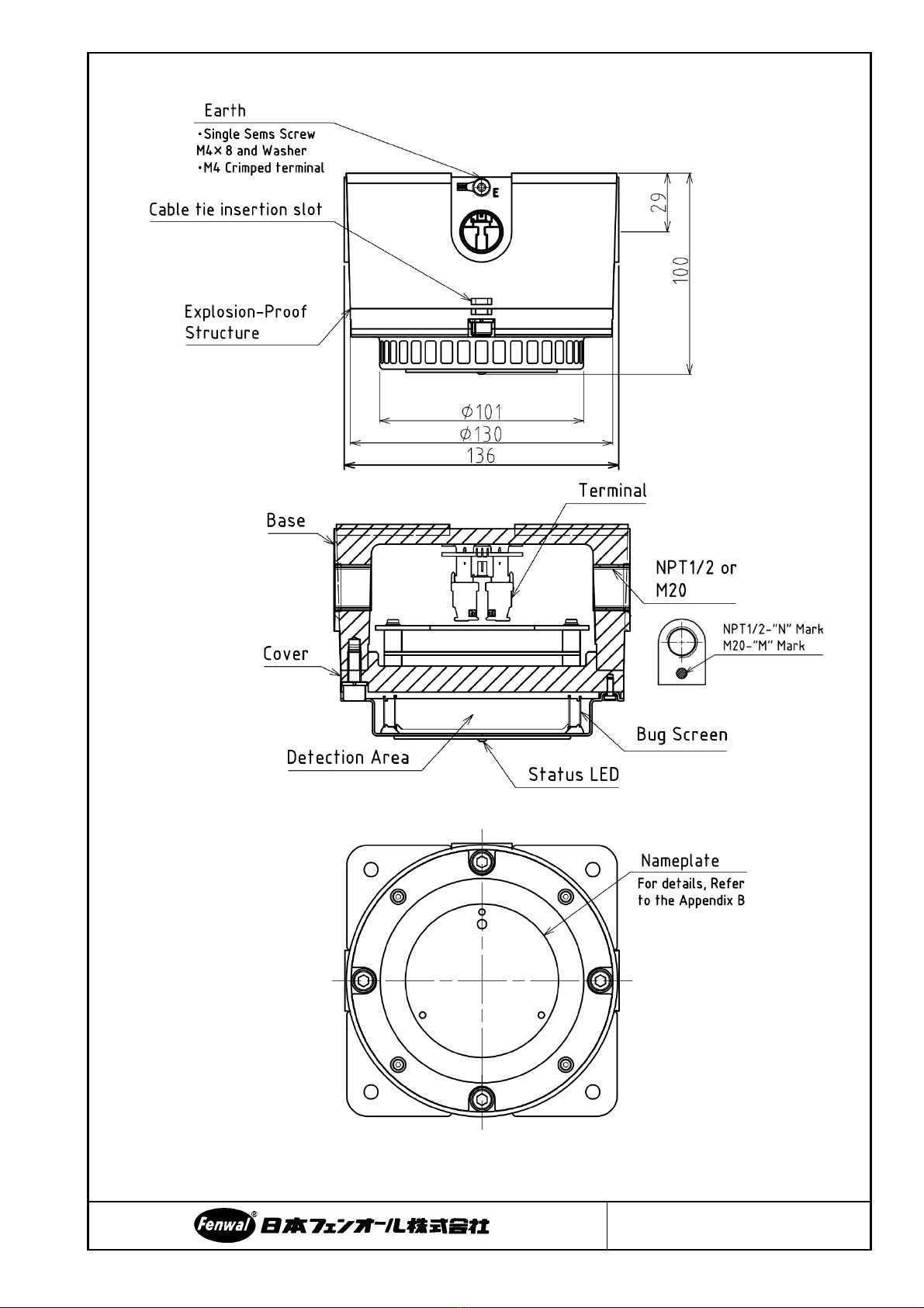
4. STRUCTURE
Figure 1 : FLS-02EC(-H2) Structure
5/13
ES1666
5. OPERATION
5.1. Status LED
Status LED indicates the state of equipment. Table 1 indicates the condition of the LED for each
status. Alarm condition takes priority over trouble condition.
Table 1 - Status LED Operation
Status of detector
LED Indicator
Normal
Blinks once in 10 seconds
Alarm
- Blinks once in 2 seconds
- this indication latching until power-cycle a
system.
Trouble
- Light out
- this indication non-latching.
5.2. Relay
FLS-02EC(-H2) has alarm and trouble relays. All relays are rated to DC24V / 1A. Table 2 indicates
the operation of each relays.
Table 2 - Relays Operation
Relay
Name
Condition
Note
Power
OFF
Normal
Alarm
Trouble
Alarm
Open
Open
Close
Open
this relay latching until
power-cycle a system.
Trouble
Open
Close
Close
Open
this relay non-latching.
5.3. Automatic Test Function
Every hour, detector supervises changes of smoke signal due to aging and dirt of sensor. When
changes of smoke signal reaches to the limit, it will result in Trouble condition.
And, detector supervises the light emission state of detection area every 24 hours (and after 60
seconds since turning on the power). When detection area is light out, it will result in Trouble
condition.
6. INSTALLATION
・FLS-02EC(-H2) must be properly installed and used according to this manual and the
specific approval certificates. Improper installation and use will invalidate warranty and
product certifications.
・Do not disassemble or repair the detector without permission. Detector repair should be
performed only by the manufacturer.
・Be certain that installation complies with all local codes. If you have questions, consult
the authority having jurisdiction before installation the system.
・Please install the detector after turning off the power.
・The FLS-02EC and FLS-02EC-H2 include flameproof joints, consult Fenwal Control of
Japan if repair of the flameproof joints is necessary.
!
WARNING
6/13
ES1666
6.1. Installation Environments
1. Temperature : 0 to +50 degree C
2. Humidity : 30 to 85%RH(However, no condensation)
3. Caution :
・Installed Indoors
・Avoid drops of water, moisture, corrosive gases, and vapors of organic solvents.
・Avoid direct sunlight and radiation by high temperature.
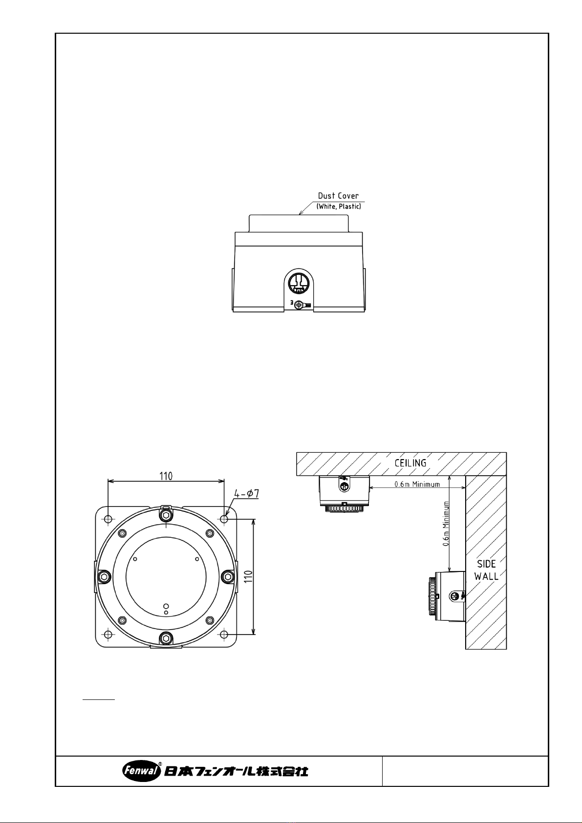
・The Dust Cover (see Figure 2) keeps dust and particles out of the smoke chamber that may
enter. Don't remove it until installation is over.
Figure 2 : Dust Cover
6.2. Mounting
1 ) Fix the FLS-02EC(-H2) to the wall with four M5 or M6 bolts using base 4-φ7 hole (See Figure 3) .
bolt length more than 11 (eleven) mm. It must be mounted on a ceiling or wall of sufficient
strength to support the weight.
2 ) It is normally mounted on the ceiling no less than 0.6 m ( twenty-four inch ) from a side wall, and
vice versa (See Figure 3).
Figure 3 : Mounting
[NOTE] FLS-02EC(-H2) separates the base and cover and packs it

7/13
ES1666
6.3. Wiring
6.3.1. Specification
Table 3 shows the pin assignments of the terminal blocks
CN4 and CN5 (See Figure 4 for exterior view).
Table3 - Pin assignments of Terminal Board
Pin No
Function
1
+24V
2
0V
3
Alarm contact-Normal Open
4
Alarm contact-Common
5
Trouble contact-Normal Close
6
Trouble contact-Common
The diameter of usable wiring is as follows.
Wiring Diameter : (Minimum) 0.2mm2 (Maximum) 2.5mm2
Case of AWG : (Minimum) 24 (Maximum) 12
The screws must be tightened down with a torque 0.5 to 0.6 N•m.
The environmental specification of the cable should be sufficient to withstand the surrounding
environment.
6.3.2. Procedure
1 ) Install the base according to "6.2 Mounting", and complete the installation of the system conduit.
Insert the external cable within the base and close the unused NPT1/2 or M20 entry with the
plug (See Figure 5). Conductor insulation of external wiring should be stripped off with a bare
conductor length of about 0.3 inch (7 mm)
Figure 5 - Install Base
Be certain that wiring complies with all local codes. If you have questions, consult
the authority having jurisdiction before wiring the system.
!
WARNING
Figure 4 - Terminal Board external view
8/13
ES1666
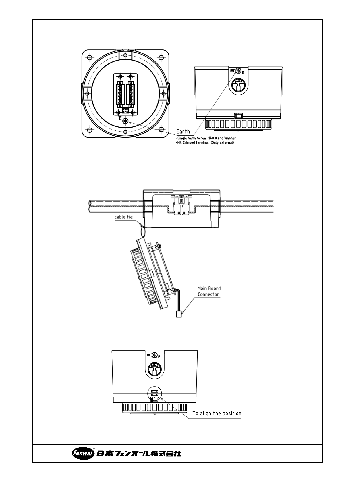
2 ) Connect the external wiring to the appropriate terminals according to "6.3.1 Specification". Refer
to Figure 6 for the earth terminal location and Figure 10 for the wiring diagram.
Figure 6 - Earth terminal
3 ) Hang the cover with a cable tie on the base, and main board connector connect to CN3 of terminal
board (See Figure 7).
Figure 7 - Connection between main board and terminal board
4 ) Attach the cover to the base and align the binding band insertion slot (See Figure 8).
Figure 8 - Attaching the cover

9/13
ES1666
5 ) Fix the 4 places with the attached M6 screw. And, close the unused NPT1/2 or M20 entry with
the plug.
Figure 9 - Fix the cover
Figure 10 - Wiring Diagram
・Please use the plug attached to the detector or one that has been certification to withstand
explosion-proof (Ex d). An example of explosion-proof plug is shown below.
NPT1/2 : CMP-757-D-T1-5 (R.STALL, INC.)
M20×P1.5 : CMP-757-D-M2-5 (R.STALL, INC.)
・Consult with Fenwal Controls of Japan, Ltd. for genuine replacement cover fasteners:
M6X20 hexagon bolts of A2-70 strength class SUS304 stainless steel or better are
acceptable alternatives.
!
WARNING

10/13
ES1666
7. MAINTENANCE AND INSPECTION
In order to check that the system is functioning correctly, it is recommended to perform maintenance
and inspection according to environment (Standard once a year).
FLS-02EC(-H2) can be tested using the same methods employed for any photo-electric detector. For
example, test smoke can be used.
If the detector are in fails condition (do not responding to the operation test, the status indicator
does not light up, etc), please turn off. Then contact us. The detector is not designed to be repaired in
the field.
[Note]
If signal transfer output of an error or alarm to external devices is likely to occur during maintenance,
ensure to inform the Customer’s department in-charge in advance, and then conduct the inspection.
Moreover, when buzzer is going to ring, notify the people in surrounding area beforehand.
Since in many cases it is necessary to move furniture and equipments of customer during
maintenance, discuss closely with the customer in advance and ensure that operators are not injured
and other equipments are not damaged.
11/13
ES1666
8. ORDERING INFORMATION
When ordering, please specify. Refer to FLS-02EC(-H2) Model Matrix for details.
FLS-02EC(-H2) Model Matrix
MODEL
DESCRIPTION
NOTE
FLS-02EC
Explosion Proof Smoke Detector
-H2
Support to hydrogen gas
See Appendix for details.
-(None)
No support to hydrogen gas
-M
Metric thread (M20)
-N
NPT thread (NPT1/2)
1
Plug:1
Quantity of attached plug
2
Plug:2
3
Plug:3
9. CONTACT US
Please contact our authorized distributors, or the head office or sales offices of the Fenwal Controls
of Japan, Ltd. in inquiring about the product.
Fenwal Controls of Japan, Ltd.
2nd floor, Kyouhan Kudan Bldg., 1-5-10, Iidabashi, Chiyoda-ku, Tokyo, Japan, 102-0072
Tokyo Head Office : (+81)-3-3237-3565
Web Inquiry : http://www.fenwal.co.jp/en/form/

12/13
ES1666
APPENDIX A
FM Certification
FM18US0151X
FLS-02EC Class I, Division 1, Group C,D T6
Class I, Zone 1, AEx db IIB T6 Gb
FLS-02EC-H2 Class I, Division 1, Group B,C,D T6
Class I, Zone 1, AEx db IIB+H2 T6 Gb
Approval Standards
ANSI / ISA 60079-0:2013 Explosive atmospheres - Part 0: Equipment - General Requirements
ANSI / UL 60079-1:2015 Explosive atmospheres - Part 1: Equipment protection by flameproof
enclosures “d”
FM 3600(2018) Electrical Equipment for Use in Hazardous (Classified) Locations -
General Requirements
FM 3615(2018) Explosionproof Electrical Equipment General Requirements
FM 3230(2019) Smoke Actuated Detectors For Automatic Fire Alarm Signaling
IECEx Certification
IECEx FMG 16.0040X
FLS-02EC Ex db IIB T6 Gb
FLS-02EC-H2 Ex db IIB+H2 T6 Gb
Approval Standards
IEC 60079-0:2011 (Ed.6) Explosive atmospheres - Part 0: Equipment - General Requirements
IEC 60079-1:2014 (Ed.7) Explosive atmospheres - Part 1: Equipment protection by flameproof
enclosures “d”
ATEX Certification
FM16ATEX0107X
FLS-02EC II 2 G Ex db IIB T6 Gb
FLS-02EC-H2 II 2 G Ex db IIB+H2 T6 Gb
Approval Standards
EN 60079-0:2012+A11:2013 Explosive atmospheres - Part 0: Equipment - General Requirements
EN 60079-1:2014 Explosive atmospheres - Part 1: Equipment protection by flameproof
enclosures “d”
Special Conditions For Safe Use X:
1. The FLS-02EC and FLS-02EC-H2 include flameproof joints, consult Fenwal Controls of Japan,
Ltd. if repair of the flameproof joints is necessary.
2. Consult with Fenwal Controls of Japan, Ltd. for genuine replacement cover fasteners: M6X20
hexagon bolts of A2-70 strength class SUS304 stainless steel or better are acceptable
alternatives.
13/13
ES1666
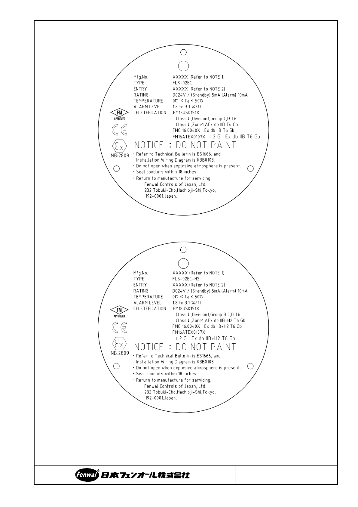
APPENDIX B
FLS-02EC Nameplate
FLS-02EC-H2 Nameplate
NOTE
1. Mfg.No. is unique number of product.
2. ENTRY is thread size (M20×P1.5 or NPT1/2).
This manual suits for next models
1
Table of contents
Other Fenwal Smoke Alarm manuals


 User manual")


