resideo 5800SMOKEV Assembly instructions

5800SMOKEV
Wireless Smoke/Heat Detector
Installation and Setup Guide
GENERAL INFORMATION
This is a multi-criteria wireless smoke
detector which employs advanced levels of
detection and discrimination. This reduces
common cooking nuisance alarms and
allows faster detection to different types of
fire conditions. It is intended for use with
Control Panels that support 5800 series
devices.
To remove the mounting bracket, turn
the top of the detector 15 degrees
counterclockwise and separate the
mounting bracket and top cover.
5800SMOKEV
Open
ENROLLMENT
The smoke detector must be enrolled in the Control Panel before it
can operate in the system. The 5800SMOKEV smoke/heat
protection zone must be enrolled as Loop 1 and “Input Type” 3
(supervised RF).
If programmed, this smoke detector is capable of monitoring the
additional conditions of Maintenance (transmitted as Loop 2), and
Low Temperature (transmitted as Loop 3). Tamper is transmitted as
Loop 4, but does not require programming. To take advantage of
the value added features of Maintenance and Low Temperature, you
must program each loop as a separate zone in the 5800 series
wireless compatible panel.
1. Enter the Control’s Zone Programming mode.
2. Enter the zone number to be programmed.
3. Enter the applicable zone type when prompted. Program
•Loop 1 (Heat/Smoke) as a Fire zone (type 9 or 16),
•Loop 2 (High/Low Maintenance) as a 24-Hr. Trouble zone (type
19), and
•Loop 3 (Freeze Warning Sensor) as a 24-Hr. Aux. zone (type 8).
NOTE: Loop 2 High/Low Maintenance is supported only on
commercial control panels such as the Vista-128FBP.
4. When prompted, enter Input Type 03 (3 on some control panels)
– Supervised RF Transmitter.
5. When prompted for the serial number, transmit from the
detector by activating the tamper switch. To do this, hold
the base of the detector in one hand, and rotate the
detector counterclockwise on the base until it snaps
open. Then return to clockwise position until the detector
snaps into place.
6. When the serial number is displayed, transmit from the
detector a second time by activating the tamper switch
again as described in Step 5. The current loop number
(4) will begin to flash.
7. Manually change the loop number to the desired loop
number for the zone (according to the application).
8. When programming for this zone is complete, program
other zones for the transmitter as necessary (except for
Tamper Loop 4, which does not require programming).
WARNING: The fire protection zone enrolled must
always be Loop 1. Otherwise, fire annunciations will
not be reported by the Control Panel.
9. Exit Programming mode when programming is complete
and test the detector. Refer to the Testing Section.
See the Control Panel’s installation instructions for further
details.
PROGRAM
Consult the Control Panel’s instructions to program the device in the system. This detector reports the following signals to the
Control Panel:
•Smoke and Heat detection
-Smoke Alarm when smoke is detected
-Heat Alarm when temperature of 135° F (57° C) or greater
-Rate-of-Rise Alarm when temperature is >104° F (40° C) @ 15° F/minute (8.33° C/minute).
•Maintenance: Contaminated chamber that requires cleaning
•End-of-Life
•Base Tamper: It sends a tamper signal to the Control Panel when the smoke head is removed from its base.
•Supervision: The detector will transmit its status every 60-70 minutes.
TAMPER
When the detector is removed from its base, it sends a
tamper signal to the Control Panel. OPTIONAL: The
detector can be made tamper-proof to prevent unauthorized
removal from its base. Break off the small pillar on the
base as shown. This causes the detector to latch to the
base. From this point on, to remove the detector from its
base, you must use a small screwdriver to release the catch
(push the catch towards the base) and twist the detector
counterclockwise. A screw can be added to prevent
removal from the base.

MOUNT
Refer to the Limitations of Fire Alarm Systems (P/N 800-15144) for
detailed information on detector spacing, placement zoning and
special applications. Copies of this document are available on
www.resideo.com.
NOTE: Before mounting the detector permanently, conduct a Walk
test (see Control Panel’s instructions) to verify adequate signal
strength and adjust the device location and orientation as
necessary.
The detector can be mounted on the ceiling or on the wall (if local
ordinances permit). Select a location and mount using the included
mounting hardware.
Mount
DO NOT attach the detector to removable ceiling
panels. Attach the detector across panel support as
shown on the accompanying figure.
TESTING
The detector should be tested immediately after installation and at least once a year.
Recommended: Notify the Central Station that the smoke detector is undergoing tests, so they do not dispatch authorities.
After enrolling, verify adequate signal strength by conducting a sensor test (see the Control Panel’s instructions) with the device in
its intended mounting location. Adjust the device location and orientation as necessary.
Tests and testing methods
There is no specific Test Mode that needs to be initiated to test smoke, heat, or Rate-of-Rise. These can be applied to the
detector at any time as a test.
•Test Button – When the Test Button is held down, the unit initiates a test on the smoke sensor, chamber, heat sensor, End-of-
Life, and battery. If all tests pass, it sounds a normal alarm and sends alarm signal to the Control Panel. However, if one of
these tests fails, it sends a trouble signal to the Control Panel and provides fail status on the yellow led and sounder. The
Test Button is also used to silence or Hush the detector. To Hush the detector, press and release the large Test Button.
Depending on how much smoke is still in the chamber determines if the Hush feature silences the detector and make it send
an Alarm restore to the Control Panel. If there is too much smoke still in the chamber, it does not Hush nor send a restore to
the Control Panel. When Hush is successful, the sounder comes back on after 10 minutes and a restore signal is still not sent
provided there is still enough smoke in the chamber to be considered an alarm. Once the smoke level is below threshold in
the chamber, Hush causes the sounder to remain off and the restore signal is sent. See the LED and Sounder Indication
Chart on the next page.
•Smoke Entry Test (canned smoke*) – Can be done at any time. Once the chamber is clear, the sounder will stop, and it will
send a restore signal to the Control Panel.
•Direct Heat Test (hair dryer 12” or further from the detector)
•135° F fixed Heat Detection
•Rate-of-Rise >104° F (40° C) @ 15° F/minute (8.33° C/minute).
CAUTION: The detector alarms when 135° F is exceeded and restore when it falls below 135° F. However, the thermistor is
damaged at 195° F and the integrity of the detector itself is compromised and needs to be replaced.
SMOKEV_C OMMON-002-V0

LEDS AND SOUNDER
The
5800SMOKEV has one bi-color (red and yellow) LED with an 85dB sounder.Refer to the
following
table below for operation of these features.
LED and Sounder Indication Chart
Normal Operation
Action
Red LED
Yellow LED
Sounder
Reaction
Power Up
Pull Battery Tab
1 Flash 1 Flash Off
Tamper
Remove from base
Off Off Off
Standby - Normal Off Off Off
Sensing Smoke / Heat
Smoke / Fire
Condition
Rapid
flashing Off Temporal 3 Evacuate Premises
Alarm Hush
Action
Red LED
Yellow LED
Sounder
Reaction
Silence Sounding Alarm
Press & Release
Button
1 flash every
8 seconds Off Off for 10 mins
Silence Low Battery
Press & Release
Button Off Off for 12 hours Off for 12 hours Replace both batteries
Silence Faulty Sensor
(only possible once)
Press & Release
Button
Off
2 flashes every
48 seconds Off for 12 hours Replace unit
Silence End of Life (up to
30 days)
Press & Release
Button Off Off for 72 hours Off for 72 hours Replace unit
Self-Diagnostics
Action
Red LED
Yellow LED
Sounder
Reaction
Low Battery
Automatic every
16 minutes
Off
1 flash every
48 seconds
1 beep with 1
flash Replace both batteries
Faulty Smoke Sensor
Automatic every
16 seconds
Off
2 flashes every
48 seconds
2 beeps with 2
flashes Replace unit
Faulty Heat Sensor
Automatic every
second
Off
2 flashes every
48 seconds
2 beeps with 2
flashes Replace unit
End of Life
Automatic every 4
hours
Off
3 flashes every
48 seconds
3 beeps with 3
flashes
Replace unit
Maintenance
Automatic every
16 seconds
Off
4 flashes every
48 seconds Off
Clean unit; see Cleaning
section
Test Button
Action
Red LED
Yellow LED
Sounder
Reaction
Detector Status Good –
Normal Alarm
Press & Hold
Button
Rapid
flashing Off
Temporal 3
Release button
Low Battery
Press & Hold
Button Off
1 flash then
rapid flashing
1 beep then
Temporal 3 Replace both batteries
Faulty Sensor
Press & Hold
Button Off
2 flashes then
rapid flashing 2 beeps only Replace unit
End of Life
Press & Hold
Button
Off
3 flashes then
rapid flashing
3 beeps then
Temporal 3
Replace unit
Maintenance
Press & Hold
Button Off
4 flashes then
rapid flashing
4 beeps then
Temporal 3
Clean unit; see Cleaning
section
Alarm Memory
Action
Red LED
Yellow LED
Sounder
Reaction
24 Hour Memory After Alarm
2 flashes every
48 seconds for
24 hours Off Off Press & Hold Button for
Long Term Memory
Long Term Memory
Press & Hold
Button
Rapid
flashing Off Rapid chirping
Memory is reset after
releasing the test button
CLEANING
Recommended: To prevent unwanted alarms, notify the Central Station that the
smoke detector system is undergoing maintenance before cleaning the detector.
To clean the detector, carefully vacuum the side vents all the way around, then,
wipe them with a clean damp cloth and dry thoroughly.
Do NOT attempt to take the detector apart. This could result in damaging the unit.
Cleaning

SPECIFICATIONS
Smoke Detection: ..................................................................................................................................................................................Photoelectric
Heat Detection: .......................................................................................................................................................135° F (57° C) or greater +/- 5°F
Rate of Rise: ................................................................................................................................>104° F (40° C) @ 15° F/minute (8.33° C/minute).
dB Rating:........................................................................................................................................................................... >85dBA (Minimum) at 9ft
Batteries: ......................................................................................................................................................... Two 3V Lithium; Panasonic CR123A
RF Frequency: .............................................................................................................................................................................................. 345MHz
Tamper: ................................................................................................................................................................................................. Base Tamper
Operating Temperature: .............................................................................................................................................40° to 100° F / 4.4° to 37.7° C
Relative Humidity: ............................................................................................................................................................95% max. non-condensing
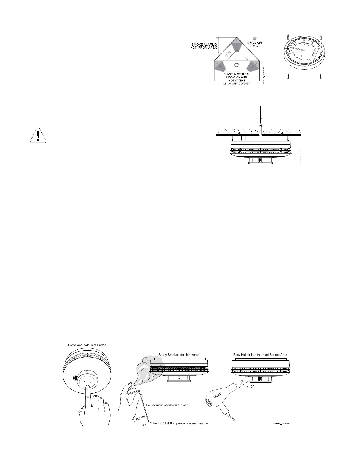
Maximum Spacing: ............................................... 50ft x 50ft (refer to National Fire Alarm Code Standard NFPA 72 for application requirements)
Dimensions: .................................................................................................4.74 in. Diameter x 2.31 in. Thick / 12.03 cm Diameter x 5.81 cm Thick
Approval Listings
FCC / IC
UL Listed – Conforms to UL 268 7th Edition Commercial and Residential Installations
ULC Listed – Certified to UL268 & CAN/ULC S529
Other Standards: State of California requirement – free of substances that may cause cancer. Prop 65 US.
NFPA 72
Note: Smoke detectors are not to be used with detector guards unless the combination is evaluated and found suitable for that purpose.
REFER TO THE INSTALLATION INSTRUCTIONS FOR THE CONTROL PANEL WITH WHICH THIS DEVICE IS USED, FOR DETAILS REGARDING LIMITATIONS
OF THE ENTIRE ALARM SYSTEM.
FEDERAL COMMUNICATIONS COMMISSION (FCC) & ISED STATEMENTS
The user shall not make any changes or modifications to the equipment unless authorized by the Installation Instructions or User's Manual. Unauthorized changes or
modifications could void the user's authority to operate the equipment.
FCC CLASS B DIGITAL DEVICE STATEMENT
This equipment has been tested and found to comply with the limits for a Class B digital device, as defined by FCC Rules Part 15.105. The Class B Digital Device
statement can be viewed at:
https://customer.resideo.com/en-US/support/residential/codes-and-standards/FCC15105/Pages/default.aspx
ISED CLASS B STATEMENT
This Class B digital apparatus complies with Canadian ICES-003.
Cet appareil numérique de la classe B est conforme à la norme NMB-003 du Canada.
FCC / ISED STATEMENT
This device complies with Part 15 of the FCC Rules, and Industry Canada’s license-exempt RSSs. Operation is subject to the following two conditions: (1) This device
may not cause harmful interference, and (2) This device must accept any interference received, including interference that may cause undesired operation.
Cet appareil est conforme à la partie 15 des règles de la FCC et exempt de licence RSS d’Industrie Canada. Son fonctionnement est soumis aux conditions suivantes: (1)
Cet appareil ne doit pas causer d’interférences nuisibles. (2) Cet appareil doit accepter toute interférence reçue y compris les interférences causant une réception
indésirable.
Responsible Party / Issuer of Supplier’s Declaration of Conformity: Ademco Inc., a subsidiary of Resideo Technologies, Inc., 2 Corporate Center Drive., Melville, NY
11747, Ph: 516-577-2000
The product should not be disposed of with other household waste. Check for the nearest authorized collection centers or authorized recyclers. The correct disposal of
end-of-life equipment will help prevent potential negative consequences for the environment and human health.
Any attempt to reverse-engineer this device by decoding proprietary protocols, de-compiling firmware, or any similar actions is strictly prohibited.
For the latest documentation, support, and warranty information, please go to: www.resideo.com
This product is manufactured by Resideo Technologies, Inc. and its affiliates.
R800-26635A 2/21 Rev A
2 Corporate Center Drive, Suite 100
P.O. Box 9040, Melville, NY 11747
2021 Resideo Technologies, Inc.
www.resideo.com
BATTERY REPLACEMENT
1. Twist the front cover counterclockwise 15 degrees and separate it
from the mounting bracket.
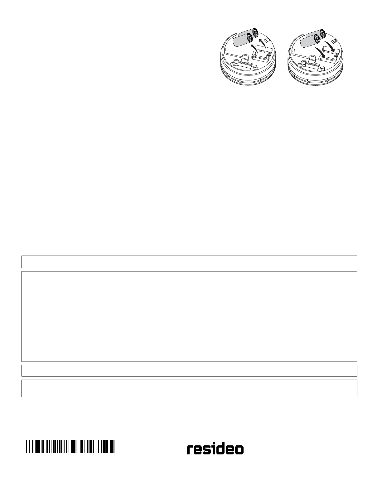
2. Remove both batteries and wait 10 seconds, then insert two new
recommended batteries:
•Panasonic CR123A
NOTE: Do not mix old and new batteries, battery types or manufacturers.
3. Reattach the detector to the mounting plate.
BATTERY CAUTION: Risk of fire, explosion and burns. Do not recharge,
disassemble, heat above 212° F (100° C) or incinerate. Dispose of used batteries
properly. Keep away from children
Replace Batteries
5800SMOKEV Series transmitters draw quick bursts of current during transmission, then sit idle with very nominal current draw. Most batteries are not
designed for this type of use, therefore, only batteries listed as compatible should be used if the expected battery life is to be attained. Each transmitter’s
Installation Instructions has listed compatible battery manufacturers and their part numbers. When other non-approved batteries are used, the quick bursts of
current draw kill the battery cells prematurely causing them to go low in a matter of months and can also cause unpredictable results. Other low-quality
batteries have not been UL tested and pose a safety hazard if used.
SMOKEV_COMMON-001-V0
Other resideo Smoke Alarm manuals