Ferrida FRD-MS2518SE User manual
Miter Saw
FRD-MS2518SE
User Manual


ENGLISH 4
DEUTSCH 18
ČESKY 34
SLOVENSKY 48
MAGYAR 62
WARRANTY & SUPPORT 77
GARANTIE & BETREUUNG 77
ZÁRUKA & PODPORA 77
ZÁRUKA & PODPORA 77
GARANCIA & TÁMOGATÁS 77
4ENGLISH
EXPLANATION OF SYMBOLS ON THE PRODUCT PACKAGING/TYPE LABEL
Read the operating instructions careful-
ly before use! Wear protective gloves
Wear mouth and nose protection. Wear noise protection.
Wear protective glasses
Observe the safety instructions con-
cerning recoil and the safety precau-
tions.
Protect from rain and moisture. Protect from heat and fire.
Ensure proper recycling of the product
at the end of its service life and all pack-
aging materials.
Do not dispose of with normal house-
hold waste.
WARNING:
Class 2 laser product. Do not look into the la-
ser beam.
GENERAL SAFETY INSTRUCTIONS FOR POW-
ER TOOLS
WARNING! All safety instructions, user man-
uals, images and regulations supplied with
these tools must be read. Failure to follow all
of the following instructions may result in elec-
tric shock, fire, and/or serious personal injury.
All instructions and the user manual must be
kept for future reference.
Safety of working environment
1. The workplace must be kept clean and well lit.
Untidy and dark spaces are often the cause of
accidents.
2. Power tools must not be used in potentially ex-
plosive atmospheres, such as in the presence
of flammable liquids, gases or dust. Power tools
create sparks that can ignite dust or fumes.
3. Children and other persons must be kept away
when using power tools. If the operator is dis-
turbed, he/she may lose control of the opera-
tion.
Electrical safety
1. The plug on the power tool's flexible lead must
match the power outlet. The plug must never
be modified in any way. No socket adapters
may be used with tools that have a protective
earth connection. Plugs and respective sockets
that are rendered unusable will reduce the risk
of electric shock.
2. The operator must not touch grounded ob-
jects, such as pipes, central heating units,
cookers and refrigerators. The risk of electric
shock is greater if your body is connected to
the ground.
3. Power tools must not be exposed to rain, mois-
ture or wetness. If water enters the power tool,
the risk of electric shock increases.
4. The flexible supply must not be used for oth-
er purposes. The power tool must not be car-
ried or pulled by the cord, nor must the plug
be unplugged from the socket. The inlet must
be protected from heat, grease, sharp edges
or moving parts. Damaged or tangled leads
increase the risk of electric shock.
5. If the power tool is used outdoors, an extension
cord suitable for outdoor use must be used. Us-
ing an extension cord for outdoor use reduces
the risk of electric shock.
6. If the power tool is used in a humid environ-
ment, a residual current device (RCD) must be
SAFETY INSTRUCTIONS

5ENGLISH
used. Using an RCD reduces the risk of electric
shock.
Safety of persons
1. When using a power tool, the operator must
be careful, pay attention to what he/she is do-
ing, and concentrate and think clearly. Power
tools must not be used if the operator is tired
or under the influence of drugs, alcohol or
medication. Momentary inattention while us-
ing a power tool can result in serious personal
injury.
2. Use personal protective equipment. Always
use eye protection. Protective equipment such
as a respirator, non-slip safety shoes, hard hat
and hearing protection, used in accordance
with the working conditions, reduces the risk
of personal injury.
3. Unintentional starting of the machine must be
avoided. Make sure that the switch is in the
off position before plugging in and/or con-
necting the battery pack, lifting or carrying
the tool. Carrying a tool with your finger on
the switch or plugging in a tool fork with the
switch on can cause injury.
4. All adjusting tools or wrenches must be re-
moved before turning on the tool. An adjust-
ing tool or wrench that remains attached to
the rotating part of the power tool may result
in personal injury.
5. The operator must only work where he/she
can safely reach. The operator must always
maintain a stable posture and balance. This
will allow better control of the power tool in
unforeseen situations.
6. Dress appropriately. Do not wear loose cloth-
ing or jewellery. The operator must make sure
that his/her hair and clothing are a sufficient
distance away from moving parts. Loose cloth-
ing, jewellery and long hair can be caught in
moving parts.
7. Where equipment is provided for connecting
dust extraction and collection facilities, care
must be taken to ensure that it is connected
and used correctly. The use of such equip-
ment can reduce hazards caused by dust.
8. The operator must not allow the routine that
results from the frequent use of the tools, to
cause them to become complacent and ig-
nore the principles of tool safety. Careless
activity can cause serious injuries in a split
second.
Use and the maintenance of power tools
1. Power tools must not be overloaded. It is es-
sential to use the correct power tool for the
work being carried out. The correct power tool
will do the work it was designed to do better
and safer.
2. Power tools that cannot be turned on and off
with the switch must not be used. Any power
tool that cannot be operated with the switch is
dangerous and must be repaired.
3. Before making any adjustments, changing ac-
cessories, or storing power tools, unplug the
power tool and/or remove the battery pack
from the power tool if it is removable. These
precautions reduce the risk of accidentally
starting the power tool.
4. Unused power tools must be stored out of the
reach of children. Persons unfamiliar with the
power tool or these instructions must not be
allowed to use the power tool. Power tools
are dangerous in the hands of inexperienced
users.
5. Power tools and accessories must be main-
tained. The adjustment of moving parts and
their mobility must be checked and attention
focused on cracks, broken parts and any other
circumstances that may jeopardize the func-
tion of the power tool. If the tool is damaged, it
must be repaired before use. Many accidents
are caused by poorly maintained power tools.
6. Cutting tools must be kept sharp and clean.
Properly maintained and sharpened cutting
tools are less likely to catch on material or jam
and are easier to control.
7. Power tools, accessories and tool bits etc.
must be used in accordance with these in-
structions and in the manner intended for the
particular power tool, taking into account the
working conditions and the work to be carried
out. Using power tools for activities other than
those for which they are designed can lead to
dangerous situations.
8. Handles and grip surfaces must be kept dry,
clean and free of grease. Slippery handles and
gripping surfaces mean the tool cannot be
held and controlled in unexpected situations.
Service
1. Power tool repairs must be carried out by
SAFETY INSTRUCTIONS

6ENGLISH
SAFETY INSTRUCTIONS
qualified personnel using identical spare
parts. This will ensure the same level of safety
of the power tool as before the repair.
SAFETY INSTRUCTIONS FOR ALL SAWS
When cutting
1. DANGER: The operator must ensure that his/
her hands are at a safe distance from the cut-
ting point and the saw disc. The other hand
must be used to grip the auxiliary handle or
the motor housing. If the saw is held with both
hands, the hands cannot be cut with the disc.
2. Do not touch the workpiece. The protective
cover cannot protect the operator from touch-
ing the disc under the workpiece.
3. The depth of cut must be adapted to the thick-
ness of the workpiece. The visible part of the
saw disc teeth under the workpiece should be
less than the height of one tooth.
4. The workpiece must never be held in the hand
or over the knee when cutting. The workpiece
must be mounted on a solid base. It is impor-
tant that the workpiece is properly supported
and that the risk of touching any part of the
body, the disc jamming, or loss of control is
reduced to the minimum.
5. When performing an operation where the cut-
ting tool may touch a hidden guide or its own
power supply, the power tool must be held
by insulated gripping surfaces. Contact with
a “live” wire will cause the uninsulated metal
parts of the power tool to become “live” and
may cause an electric shock to the user.
6. When cutting longitudinally, it is always nec-
essary to use a longitudinal ruler or a guide
with a straight edge. This improves cutting ac-
curacy and reduces the risk of the disc getting
stuck.
7. Discs with clamping holes of the correct size
and shape (diamond or circular) must always
be used. Saw discs that do not exactly match
the saw's clamping components will not be
centred and will cause a loss of control.
8. Damaged or incorrect washers or screws must
never be used to clamp the disc. The washers
and screws for clamping the disc have been
specially designed for your saw for optimum
performance and work safety.
Causes of recoil and related warnings
Recoil is a sudden reaction of a pinched, blocked
or misaligned saw disc resulting in an uncon-
trolled upward movement of the saw upwards
and away from the workpiece towards the oper-
ator;
• If the saw disc is clamped or completely
blocked by the clamping cut, it stops, and the
reaction force of the motor causes the saw to
be thrown back quickly towards the operator;
• If the saw disc is rotated or misaligned in the
cut, the teeth on the rear edge of the disc may
hit the wood surface from above, the disc will
jump out of the cut and the saw will be thrown
back towards the operator.
Recoil is the result of improper use of the saw
and/or improper work procedures or conditions
and can be prevented by fully complying with
the above precautions.
• The saw must always be held firmly with both
hands and the arms in a position that it can
withstand the force of the recoil. The body
of the operator must be on one side of the
disc, but not in the plane of the disc. Recoil
can cause the saw to be thrown back, but the
force caused by the recoil can be handled by
the user taking the appropriate safety precau-
tions.
• If the saw disc becomes stuck or if it is nec-
essary to interrupt the cut for any reason, the
switch control must be released, and the saw
held in place in the material until the saw disc
comes to a complete stop. The operator must
never attempt to lift the saw from the cut or
pull it back while the saw disc is in motion; in
such cases, recoil may occur. It is necessary to
look for the causes of the saw disc jamming
and ways to eliminate these causes.
• If the saw disc is lowered in the workpiece, the
saw disc must be centred in the cut so that the
saw teeth are not immersed in the material. If
the saw disc jams, the saw may be pushed up-
wards from the workpiece or recoil may occur.
• Large sawn timber must be supported to min-
imize the risk of recoil and the saw disc jam-
ming. Large sawn timber tends to sag under
its own weight. There must be pads on both
sides under the board near the cut and near
the edges.
• Blunt or damaged saw discs must not be used.
Unsharpened or incorrectly adjusted saw discs

7ENGLISH
create a narrow cutting groove and cause ex-
cessive friction, which limits the rotation of the
disc and leads to recoil.
• Before cutting, the levers for adjusting the
depth of the cut and the bevel angle of the
saw disc must be sufficiently and reliably tight-
ened If the disc position changes during cut-
ting, the disc may jam and recoil may occur.
• Extra care must be taken when cutting into ex-
isting walls or other places where you cannot
see. A disc that penetrates the other side of
the material can cut into the object, which can
cause recoil.
SAFETY INSTRUCTIONS FOR MITER SAWS
• Miter saws are designed for cutting wood or
wood-like materials.They cannot be used with
cutting discs to cut ferrous materials such as
rods, screws, etc. Abrasive dust can cause the
lower guard to jam. Grinding sparks can burn
the bottom guard, insert plate or other plastic
parts.
• Use the clamp to secure the workpiece when-
ever possible. When holding the workpiece by
hand, hold it at least 100 mm from both sides
of the saw disc. Do not use the saw to cut
pieces that are too small to clamp or hold. If
you place your hand too close to the saw disc,
there is an increased risk of injury from contact
with the disc.
• You must fasten the workpiece with clamps
or hold it to the stop bar and the table. Never
hold the workpiece "only in your hand" when
cutting. Unattached or moving workpieces can
be dropped at high speed and cause injury.
• Push the saw when cutting with the workpiece.
Never pull the saw through the workpiece. To
make a cut, first lift the saw head and pull it
over the workpiece without cutting. Then you
start the motor, press the saw head and push
to cut the workpiece. If you make a pull cut,
the disc could reach the top of the workpiece
and be thrown sharply toward the machine
operator.
• Never place your hands across the intended
cutting line in front of or behind the saw disc.
Holding the workpiece with the "opposite
hand", i.e. Holding with your left hand on the
right side of the saw disc and vice versa is very
dangerous.
• When the disc is in motion, do not approach
the saw disc on either side by less than 100
mm with your hand behind the stop bar, either
to remove wood chips or for other reasons.
You may not be able to estimate the distance
between your hand and the disc correctly and
you could be seriously injured.
• Inspect the workpiece carefully before cutting.
If it is crooked or bent, attach it to the stop bar
on the outside of the arch. Always check that
there is no gap between the workpiece, the
stop bar and the table along the intended cut.
Curved or warped workpieces can rotate or
shift and can pinch the saw disc when cutting.
There should be no nails or foreign objects in
the workpiece.
• Do not use the saw until you have harvested all
tools, sawdust, etc. from the table and only the
workpiece remains on it. Small pieces of wood
or other material that comes into contact with
the rotating disc can be thrown away at high
speed.
• Always cut only one workpiece. Laminated
workpieces cannot be fastened properly and
can pinch the saw disc or move during cutting.
• Before use, make sure that the saw is mounted
or placed on a firm, level surface. A solid flat
surface reduces the risk of the saw becoming
unstable.
• Plan the work in advance. Each time you
change the inclination and cutting angle set-
tings, make sure that the stop bar sufficiently
supports the workpiece and does not interfere
with the discs or the protection system. With
a tool and no workpiece, make a blank test cut
and make sure that the stop bar does not ob-
struct or damage it.
• If you are cutting a workpiece that is wider or
longer than the top of the saw table, support it
properly with table attachments, wood cutting
goats, etc. Workpieces that are wider or longer
than the miter saw table and are not support-
ed may tip over. If the chip or workpiece is
overturned, it could lift the lower guard or be
dropped by the rotating disc.
• Do not use other people instead of table at-
tachments or as additional support. Insuffi-
cient workpiece support can cause the disc to
pinch or the workpiece to shift during cutting
and can pull you or your assistant toward the
rotating disc.
• The chip must not jam or otherwise be
SAFETY INSTRUCTIONS

8ENGLISH
SAFETY INSTRUCTIONS
pressed against the rotating disc. If the chip is
attached, such as stops, it may jam against the
disc and be thrown off sharply.
• Always fasten round materials such as rods
and tubes. The bars tend to rotate during cut-
ting, which causes the disc to "bite" and pull
your hand and the workpiece under the disc.
• Allow the disc to reach full rotation speed be-
fore cutting the workpiece. This will help re-
duce the risk of the workpiece being dropped.
• If the workpiece or disc jams, switch off the
miter saw. Wait for all moving parts to stop,
pull the plug out of the socket and/or remove
the battery. Only then remove the jammed
material. If you continue to cut through the
jammed workpiece, you could lose control of
the machine or damage the miter saw.
• When you have finished cutting, release the
switch, hold the saw head down and wait for
the disc to stop. Only then remove the clip.
Approaching the running disc with your hand
is very dangerous.
• Keep your workplace clean. Mixtures of mate-
rials are particularly harmful. Light metal dust
may burn or explode.
• Do not use any blunt, cracked, bent or dam-
aged saw discs. Saw discs with blunt or mis-
aligned teeth cause increased friction, pinch-
ing of the saw disc and kickback due to the
narrow cut gap.
• Do not use any high-alloy high-speed steel
(HSS) saw discs. Such saw discs can break eas-
ily.
• Always use saw discs of the correct size and
with a suitable clamping hole (e.g. diamond
or circular). Saw discs that do not match the
saw's mounting parts do not run centred and
lead to a loss of control.
• Never remove cutting residues, wood chips,
etc. from the cutting area while the power tool
is running. First, bring the tool arm to rest and
turn off the power tool.
• Never touch the saw disc before it has cooled
down. The saw disc is very hot during oper-
ation.

9ENGLISH
Electric miter saw
Parameter Value
AC engine - voltage 220-240 V, 50 Hz
Power consumption 2000 W
Idle revolutions 5000 min-1
Saw disc - with hard metal 255 mm × 30 mm × 2,8 mm
Number of disc teeth 60
Range of cutting angles -45°/ 0°/ 45°
Vertical cut angle 0° to 45° to the left
Maximum cutting dimensions at 90° / vertical 0° 315 × 90 mm
Maximum cutting dimensions at 45° / vertical 0° 215 × 90 mm
Maximum cutting dimensions at 90° / vertical 45° 315 × 40 mm
Maximum cutting dimensions at 45° / vertical 45° 215 × 40 mm
Electrical protection class II
Weight 16.4 kg
Laser class 2
Laser wavelength 650 nm
Laser output <1 mW
NOISE AND VIBRATION LEVEL PARAMETERS
Sound pressure level (LpA)94.3 dB(A)
uncertainty KpA 3 dB
Sound power level LwA 107.3 dB(A)
uncertainty KWA 3 dB
VIBRATION AND NOISE INFORMATION
Noise parameters and their uncertainty were measured according to EN62841-1.
Wear noise protection! Actual noise values depend on the conditions of use of the machine and
may differ from those stated, which are far from being safe values.
WAYS TO REDUCE NOISE AND VIBRATION
You can reduce noise and vibration by using tools with reduced vibration, the way you work, reducing
the time of use and wearing protective equipment.
To reduce the risk of shocks and noise, follow these recommendations:
1. Always use the product in accordance with the instructions and intended use.
2. Ensure that the product is always in perfect condition and properly maintained.
3. Use tools designed for this product and in good condition.
4. Hold the handle of the machine firmly, keep the surface clean.
5. Plan the work with regard to the distribution of exposure over a longer period.
TECHNICAL DATA
10 ENGLISH
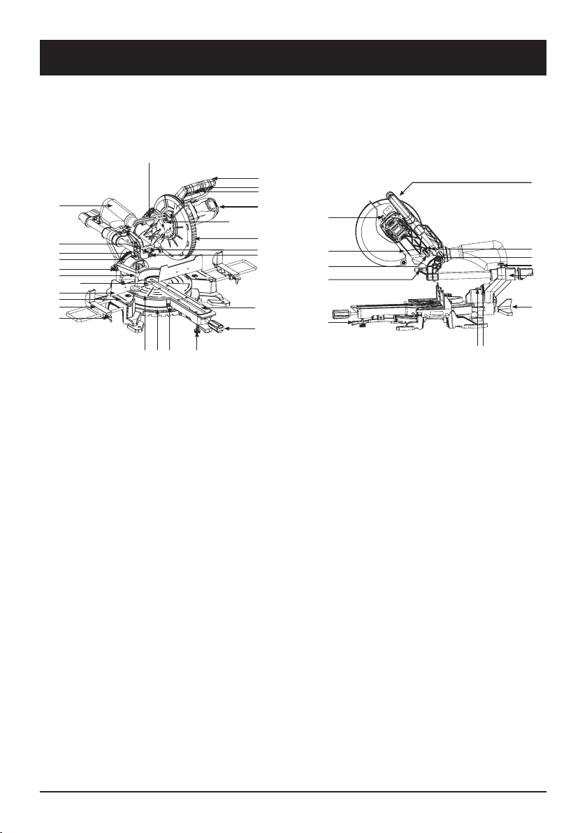
DESCRIPTION
1 Saw handle
2 Saw switch
3 Switch fuse
4 Arm of the saw
5 Movable saw disc protection
6 Saw disc
7 Clamp
8 Side supports
9 Support locking screw
10 Table insert
11 Handle with angle fixing screw
12 Angle indicator
13 Cutting angle scale
14 Turntable
15 Saw base
16 Stop bar
16a Extension block
16b Adjusting screw
17 Bag for saws
18 Vertical angle scale
19 Vertical angle indicator
20 Feed lock
21 Saw feed bearing
22 Vertical angle locking screw
23 Fastening screw
24 Depth of cut stop screw
25 Cutting depth stop
26 Arm lock
27 Support leg
28 Fixed angle stop
29 Spindle screw
30 Outer flange
31 Spindle lock
32 Inner flange
33 Laser
34 Laser switch
35 Laser body
36 Laser holder
37 Protective cover rod
33
36
9
8
11
10
1
4
5
7a
7
18
19
17
35
13 12 2714
16
15
37
16a/16b
2
3
29
30
32
34
23
26
22
1819
20
21
6
31
24
25
28

11ENGLISH
WARNING
For your own safety, only connect the power cord to the
power outlet after completing all the steps for assembling
the machine and reading this manual.
First, remove the machine from its packaging and place it
on a workbench.
SAW ASSEMBLY
• You can turn the table (14) by releasing the angle fix-
ing handle (11) and pressing the fixed angle stop (28).
• Rotate the table (14) to the desired position indicated
by the pointer (12) on the scale (13); then secure it by
turning the handle (11).
• Press the machine arm (4) down and release it by pull-
ing the arm lock (26) out of the motor cover.
• The arm can now be raised to the upper position.
• The material should be fastened with clamps (7) on
the right or left side of the machine base (15). To do
this, insert the clamp (7) into the hole on the back of
the stop rail (16) and secure it with the screw (7a).
• Insert the side supports (8) into the holes in the base
(15) according to Fig. 5 and secure the screws (9).
• The entire saw arm (4) can be inclined for miter cuts
by a maximum 45° to the left. To do this, loosen the
vertical angle locking screw (22).
PRECISE VERTICAL ANGLE ADJUSTMENT OF 90°
• Angle not included.
• Press the machine arm (4) down and secure with the
lock (26).
• Loosen the vertical angle screw (22).
• Measure the angle between the saw disc (6) and the
saw table (14) with an angle.
• Use the screw (a) to adjust the angle between the ta-
ble (14) and the saw disc (6) to exactly 90°.
• Additional fixation of the setting is not necessary, as
it is secured by a spring. However, check the angle
indicator (19). If necessary, loosen it with a Phillips
screwdriver and set the value on the scale (18) to 0°.
Then fix them again.
ASSEMBLY
1
2
3
4
11
28
8
9
15
4
26
16
7a
7
121314

12 ENGLISH
SWITCHING ON AND OFF
To switch on the machine, lower the switch lock (3) to the left,
hold it and press the switch (2).
To switch off the machine, release the switch (2).
WARNING!
Never reach into the saw disc area and into the cut. Think
about and observe the position of your body and hands when
using the saw; the right position makes work easier and in-
creases safety. Keep children away from the machine. Other
people must be kept at a safe distance from the machine and
the material when in use. Do not push on the saw. It works
best at the full speed for which it was designed.
TRANSVERSE PERPENDICULAR CUT WHEN SETTING THE
TABLE TO 0°
When cutting material up to a width of approximately 100
mm, it is possible to suppress the arm feed and leave the saw in the rear position with a fixed lock
(20). For a wider piece, you can release the lock (20) and move the saw (4) in the guide forwards and
backwards.
• Loosen the adjusting screw (16b) on the extension block (16a) and push the extension block
inwards.
• The extension block (16a) must be fixed far enough from the inner position so that the distance
between it and the saw disc (6) does not exceed 8 mm.
• Before using the machine, make sure that the extension disc (16a) cannot collide with the saw
disc (6).
• Tighten the adjusting screw (16b) again.
• Release the machine arm (4) to the upper position.
• If necessary, push the handle (1) of the saw (4) into the rear position and lock it (for narrower
material).
• Place the material to be cut on the table (14) and rest it on the stop rail (16).
• Fasten the material to the base (15) with the clamp (7) so that it cannot move during cutting.
• Grasp the saw by the handle (1) and lower it with the switch (2).
If the saw feed is blocked:
• Make the cut (1) with a slight downward pressure until the disc (6) fully cuts through the material.
If the saw feed is released:
• Pull the saw arm (4) by the handle (1) all the way forward, then push the saw (4) all the way down
with light pressure. Now push the saw (4) back slowly and regularly to the rear position until the
disc (6) completely cuts through the material.
• After cutting the material, slowly raise the arm (4) to the upper position and release the switch (2).
• Attention! The saw arm (4) returns automatically by spring pressure, so do not release the handle
(1) in the lower position, but actively guide the handle upwards.
VERTICAL CUT WHEN SETTING THE TABLE 0° - 45°
The turntable allows cuts at an angle of 0° to 45° from the plane of the disc on both sides.
USE
32

13ENGLISH
Important! For perpendicular cuts (90 ° vertical angle), the extension block (16a) must be fixed in the
inner position.
• Loosen the adjusting screw (16b) on the extension block (16a) and push the extension block
inwards.
• The extension block (16a) must be fixed far enough from the inner position so that the distance
between it and the saw disc (6) does not exceed 8 mm.
• Before using the machine, make sure that the extension disc (16a) cannot collide with the saw
disc (6).
• Tighten the adjusting screw (16b) again.
• Release the angle fixing handle (11) and lift the lock (28).
• Turn the handle (11) to the table (14) to the desired position. The angle indicator (12) must corre-
spond to the required angle value on the scale (13) on the base (15) of the machine.
• Fix the selected table angle (14) with the handle (11).
• Make the cut according to the previous paragraph "Transverse perpendicular cut at table setting
0°".
• Precise adjustment of the vertical angle at 45° (Fig. 1, 9 and 10)
• Protractor not included.
• Press the machine arm (4) down and secure with the lock (26).
• Secure the table (14) in the 0° position.
• Loosen the vertical angle screw (22) and tilt the saw arm (4) to the left at a 45° angle with the
handle (1).
• Use a protractor to measure a 45° angle between the saw disc (6) and the saw table (14).
• Use the screw (28) to adjust the angle between the table (14) and the saw disc (6) to exactly 45°.
• Additional fixation of the setting is not necessary, as it is secured by a spring.
• However, check the angle indicator (19). If necessary, loosen it with a Phillips screwdriver and set
its value on the scale (18) to 45°. Then fix them again.
OBLIQUE CUT 0° TO 45° IN TABLE POSITION 0°
The saw allows miter cuts at a vertical angle of 0° to 45° from the plane of the disc.
Important! For oblique cuts (general vertical angle), the extension block (16a) must be fixed in the
outer position.
• Loosen the adjusting screw (16b) on the extension block (16a) and push the extension block out.
• The extension block (16a) must be fixed far enough from the inner position so that the distance
between it and the saw disc (6) does not exceed 8 mm.
• Before using the machine, make sure that the extension disc (16a) cannot collide with the saw
disc (6).
• Tighten the adjusting screw (16b) again.
• Move the saw arm (4) to the upper position.
• Secure the table (14) in the 0° position.
• Loosen the vertical angle screw (22) and lower the saw arm (4) to the left to the desired position
with the handle (1). The angle indicator (19) must correspond to the required angle value on the
scale (18).
USE

14 ENGLISH
• Now tighten the vertical angle locking screw (22).
• Make the cut according to the paragraph "Transverse perpendicular cut at table setting 0°".
BAG FOR SAWS
The machine is equipped with a sawdust outlet, which can be connected to the extractor or fitted
with a sawdust bag (17).
Squeeze the metal ring around the neck of the bag and simply thread it onto the sawdust outlet neck
on the saw motor.
Clean the used bag (17) after removing it from the machine and opening the zipper.
CUTTING DEPTH LIMITATION
• For evenly shallow cuts and repeated cuts, you can set the depth of the cut with the screw (24).To
do this, first, loosen the depth adjustment screw nut (24). Move the depth of cut stop (25) to the
rear position. Turn the screw (24) until the saw teeth reach the specified depth. Hold the saw arm
in this position and tighten the nut to secure the position of the screw (24).
• Make a test cut.
OBLIQUE CUT 0° TO 45° IN TABLE POSITION 0° TO 45°
The saw allows miter cuts at a vertical angle of 0° to 45° from the plane of the disc and at the same
time angular cuts 0° to 45° from the vertical plane of the disc.
Important! For oblique cuts (general vertical angle), the extension block (16a) must be fixed in the
outer position.
• Loosen the adjusting screw (16b) on the extension block (16a) and push the extension block out.
• The extension block (16a) must be fixed far enough from the inner position so that the distance
between it and the saw disc (6) does not exceed 8 mm.
• Before using the machine, make sure that the extension disc (16a) cannot collide with the saw
disc (6).
• Tighten the adjusting screw (16b) again.
• Move the saw arm (4) to the upper position.
• Release the angle fixing handle (11) and lift the lock (28).
• Turn the handle (11) to the table (14) to the desired position. The angle indicator (12) must corre-
spond to the required angle value on the scale (13) on the base (15) of the machine.
• Fix the selected table angle (14) with the handle (11).
• Loosen the vertical angle screw (22) and lower the saw arm (4) to the left to the desired position
with the handle (1). The angle indicator (19) must correspond to the required angle value on the
scale (18).
• Now tighten the vertical angle locking screw (22).
• Make the cut according to the paragraph "Transverse perpendicular cut at table setting 0°".
USE

15ENGLISH
USE
SAW DISCS REPLACEMENT
Important! Unplug the power cord from the outlet. It is
recommended to use thick gloves when replacing. Risk
of injury!
• Raise the machine arm (4) to the upper position.
• Using a Phillips screwdriver, disconnect the guard
cover (37) and lower it.
• Press the switch lock (3) and turn the movable saw
disc guard (5) to the open position above the saw
disc cover by pulling. The spindle screw (29) is now
accessible.
• Press and hold the spindle lock (31).Turn the saw until
the lock engages. Then insert the Allen key (d) into the
screw (29) with the other hand.
• Hold the key in the screw and slowly release the disc
guard until it rests on the key (d).
• Press the spindle lock (31) again, lock the disc and
carefully turn the key (d) to loosen the spindle screw
(29). Loosen the screw to the right because the screw
has a left-hand thread.
• Remove the bolt (29) and the outer flange (30) of the
disc.
• Remove the saw disc (6) and the inner flange (32).
• Clean flanges (30) and (32).
• Insert a new saw disc in the reverse order.
• ATTENTION: The direction of rotation of the saw disc
marked on the disc by an arrow must match the mark-
ing on the cover.
d
31
32
29 30
6
30
5
29
4

16 ENGLISH
MAINTENANCE
GENERAL MEASURES
• Regularly remove chips and dust from the machine with a cloth and brush. Lubricate moving
parts with a suitable oil once a month. Do not lubricate the engine.
• Do not use any chemicals when maintaining plastic parts.
TRANSPORT
Before transporting the machine, do the following:
• Tighten the handle (11) to secure the table (14).
• Push the saw arm (4) into the lower position and secure it with the lock (26).
• Secure the arm in the rear position with the screw (20).
• Only carry the machine by the base (15).
• Follow these instructions when assembling and re-commissioning the machine.
STORAGE
• Store the machine and its accessories in a dark,dry place that is not exposed to frost.The machine
must be kept out of reach of children. The ideal storage temperature is between 5°C and 30°C.
• Store the machine in its original packaging; protect it from moisture and dust. Keep these instruc-
tions with the machine.

17ENGLISH
Identification of the manufacturer / importer's authorised representative:
Manufacturer: Alza.cz, a. s.
Registered office: Jankovcova 1522/53, Holešovice, 170 00 Prague 7
Company ID: 27082440
Subject of the declaration:
Name: Miter saw
Model/Type: J1G-ZP28-255 / FRD-MS2518SE
The above product has been tested in accordance with the standard (s) used to demonstrate
compliance with the essential requirements set out in the Directive (s):
Machine directive 2006/42/EC
Electromagnetic compatibility (EMC) directive 2014/30/EU
ROHS directives 2011/65/EU and (EU) 2015/863
Reference to harmonised standards:
EN62841-1: 2015+AC: 15
EN62841-3-9:2015+AC:16+A11:17
EN55014-1:2017
EN55014-2:2015
EN61000-3-2:2014
EN61000-3-3:2013
EC type-examination was carried out on:
Intertek Testing Services Shanghai, Building No. 86,1198 Qinzhou Road (North), Caohejing Develop-
ment Zone, Shanghai 200233, China
Notified Body No. 0012
Certificate number: 200100937SHA-V1
Technical documentation is stored at:
Alza.cz, a. s.
Jankovcova 1522/53, Holešovice, 170 00 Prague 7
The year of manufacture of the machine and the serial number are indicated on the machine.
Ing. Jan Melena
Business Development Manager
Sales and Purchasing; Private Labels
In Prague, 22.9.2021
EC DECLARATION OF CONFORMITY
18 DEUTSCH
ERLÄUTERUNG DER SYMBOLE AUF DER PRODUKTVERPACKUNG/DEM TYPENSCHILD
Lesen Sie vor dem Gebrauch die Bedie-
nungsanleitung durch! Tragen Sie Schutzhandschuhe.
Tragen Sie einen Mund- und Nasen-
schutz. Benutzen Sie Lärmschutz.
Tragen Sie eine Schutzbrille.
Beachten Sie die Hinweise zur Rück-
laufsicherheit und deren Sicherheits-
vorkehrungen.
Vor Regen und Feuchtigkeit schützen. Vor Hitze und Feuer schützen.
Sorgen Sie für ein ordnungsgemäßes
Recycling des Produkts am Ende seiner
Lebensdauer und aller Verpackungs-
materialien.
Entsorgen Sie das Produkt nicht über
den gewöhnlichen Hausmüll.
WARNUNG:
Laserprodukt der Klasse 2. Schauen Sie nicht
in den Laserstrahl.
ALLGEMEINE SICHERHEITSHINWEISE FÜR
ELEKTROWERKZEUGE
WARNUNG! Alle Sicherheitshinweise, Bedie-
nungsanleitungen, Bilder und Vorschriften,
die mit diesem Gerät geliefert werden, müs-
sen gelesen werden. Die Nichteinhaltung der
folgenden Hinweise kann zu Stromschlag,
Brand und/oder schweren Verletzungen füh-
ren.
Alle Anleitungen und Gebrauchsanweisungen
müssen aufbewahrt werden, damit sie zu ei-
nem späteren Zeitpunkt eingesehen werden
können.
Sicherheit im Arbeitsumfeld
9. Der Arbeitsplatz muss sauber und gut beleuch-
tet sein. Unordnung und dunkle Räume sind oft
die Ursache von Unfällen.
10.Elektrowerkzeuge dürfen nicht in explosions-
gefährdeten Bereichen eingesetzt werden, in
denen brennbare Flüssigkeiten, Gase oder
Stäube vorhanden sind. Das Elektrowerkzeug
erzeugt Funken, die Staub oder Dämpfe ent-
zünden können.
11.Kinder und andere Personen müssen an der
Benutzung von Elektrowerkzeugen gehindert
werden. Wenn der Bediener gestört wird, kann
er die Kontrolle über den Vorgang verlieren.
Elektrische Sicherheit
1. Die Gabel des beweglichen Elektrowerkzeugs
muss mit der Steckdose übereinstimmen. Die
Gabel darf in keiner Weise verändert werden.
Es dürfen keine Steckdosenadapter mit Werk-
zeugen verwendet werden, die eine Schutz-
verbindung zur Erde haben. Stecker, die durch
Änderungen entwertet wurden, und entspre-
chende Steckdosen, verringern das Risiko ei-
nes Stromschlags.
2. Der Bediener darf geerdete Gegenstände wie
Rohre, Körper der Zentralheizung, Herde und
Kühlschränke nicht mit seinem Körper berüh-
ren. Die Gefahr eines Stromschlags ist größer,
wenn Ihr Körper mit dem Boden verbunden ist.
3. Elektrowerkzeuge dürfen nicht Regen, Feuch-
tigkeit oder Nässe ausgesetzt werden. Wenn
Wasser in das Elektrowerkzeug eindringt, er-
höht sich das Risiko eines Stromschlags.
4. Das bewegliche Zuleitungskabel darf nicht
für andere Zwecke verwendet werden. Elekt-
rowerkzeuge dürfen nicht am Kabel getragen
oder gezogen werden, auch darf der Stecker
SICHERHEITSHINWEISE

19DEUTSCH
durch Ziehen am Kabel nicht aus der Steck-
dose gezogen werden. Das Zuleitungskabel
muss vor Hitze, Fett, scharfen Kanten oder
beweglichen Teilen geschützt werden. Be-
schädigte oder verhedderte Zuleitungskabel
erhöhen das Risiko eines Stromunfalles.
5. Wenn das Elektrowerkzeug im Freien ver-
wendet wird, muss ein für den Außeneinsatz
geeignetes Verlängerungskabel verwendet
werden. Die Verwendung eines Verlänge-
rungskabels für den Einsatz im Freien verrin-
gert das Risiko eines Stromschlags.
6. Wenn Elektrowerkzeuge in feuchten Berei-
chen verwendet werden, muss eine durch
einen Fehlerstromschutzschalter (RCD) ge-
schützte Stromversorgung verwendet werden.
Der Fehlerstromschutzschalter (RCD) redu-
ziert Stromunfälle.
Sicherheit von Personen
1. Bei der Verwendung von Elektrowerkzeugen
muss der Bediener aufmerksam sein, sich kon-
zentrieren und rational denken. Elektrowerk-
zeuge dürfen nicht verwendet werden, wenn
der Bediener müde ist oder unter dem Ein-
fluss von Drogen, Alkohol oder Medikamen-
ten steht. Ein Moment der Unachtsamkeit bei
der Verwendung von Elektrowerkzeugen kann
zu schweren Verletzungen führen.
2. Tragen Sie eine persönliche Schutzausrüs-
tung. Tragen Sie stets Augenschutz. Schutz-
ausrüstungen wie Schutzmasken, rutschfeste
Sicherheitsschuhe, harte Kopfbedeckungen
oder Gehörschutz, die entsprechend den Ar-
beitsbedingungen verwendet werden, verrin-
gern das Risiko von Personenverletzungen.
3. Ein unbeabsichtigtes Einschalten der Maschi-
ne muss vermieden werden. Vergewissern Sie
sich, dass der Schalter auf „Aus“ steht, bevor
Sie den Stecker in die Steckdose stecken und/
oder den Akku anschließen, das Gerät anhe-
ben oder tragen. Das Tragen des Geräts mit
dem Finger auf dem Schalter oder das Einste-
cken der Werkzeuggabel bei eingeschaltetem
Schalter kann zu Unfällen führen.
4. Vor dem Einschalten des Geräts müssen alle
Einstellwerkzeuge oder Einstellschlüssel ent-
fernt werden. Ein Einstellwerkzeug oder Ein-
stellschlüssel, der an einem rotierenden Teil
des Elektrowerkzeugs bleibt, kann zu Verlet-
zungen führen.
5. Der Bediener darf nur an Stellen arbeiten, die
er sicher erreichen kann. Der Bediener muss
stets eine stabile Körperhaltung einnehmen
und das Gleichgewicht halten. Dies ermög-
licht eine bessere Kontrolle des Elektrowerk-
zeugs in unvorhergesehenen Situationen.
6. Kleiden Sie sich angemessen. Tragen Sie we-
der lose Kleidung noch Schmuck. Der Bedie-
ner muss darauf achten, dass Haare und Klei-
dung von beweglichen Teilen ferngehalten
werden. Lose Kleidung, Schmuck und lange
Haare können von beweglichen Teilen erfasst
werden.
7. Sind Vorrichtungen für den Anschluss von
Staubabsaug- und -sammelgeräten vorhan-
den, so muss sichergestellt werden, dass die-
se Geräte ordnungsgemäß angeschlossen
und verwendet werden. Durch den Einsatz
dieser Geräte können die durch den entste-
henden Staub verursachten Gefahren verrin-
gert werden.
8. Der Bediener darf nicht zulassen, dass er
bei der Routine, die sich aus dem häufigen
Gebrauch des Werkzeugs ergibt, zu selbst-
bewusst wird und er die Grundsätze der
Werkzeugsicherheit ignoriert. Unvorsichtiges
Handeln kann in Sekundenbruchteilen zu
schweren Verletzungen führen.
Verwendung und Wartung von Elektrowerk-
zeugen
1. Elektrowerkzeuge dürfen nicht überlastet wer-
den. Es ist wichtig, die richtigen Elektrowerk-
zeuge für die durchzuführenden Arbeiten zu
verwenden. Das richtige Elektrowerkzeug leis-
tet mehr und ist sicherer bei der Arbeit, für die
es entwickelt wurde.
2. Verwenden Sie keine Elektrowerkzeuge, die
nicht mit einem Schalter ein- und ausgeschal-
tet werden können. Ein Elektrowerkzeug mit
einem defekten Hauptschalter ist gefährlich
und muss repariert werden.
3. Vor jeder Einstellung, jedem Zubehörwech-
sel oder jeder Lagerung des Elektrowerk-
zeugs müssen die Stecker aus der Steckdose
gezogen und/oder der Akku aus dem Elek-
trowerkzeug entfernt werden, wenn er her-
ausnehmbar ist. Diese vorbeugenden Sicher-
heitsmaßnahmen reduzieren das Risiko einer
versehentlichen Inbetriebnahme des Elektro-
werkzeugs.
SICHERHEITSHINWEISE

20 DEUTSCH
SICHERHEITSHINWEISE
4. Unbenutzte Elektrowerkzeuge müssen außer-
halb der Reichweite von Kindern aufbewahrt
werden, und Personen, die nicht mit Elektro-
werkzeugen oder dieser Anleitung vertraut
sind, dürfen sie nicht benutzen. Das Elektro-
werkzeug könnte in den Händen von unerfah-
renen Anwendern gefährlich sein.
5. Elektrowerkzeuge und Zubehör müssen ge-
wartet werden. Die Ausrichtung der beweg-
lichen Teile und ihre Beweglichkeit müssen
überprüft werden, wobei auf Risse, gebroche-
ne Teile und andere Umstände zu achten ist,
die die Funktion des Elektrowerkzeugs be-
einträchtigen könnten. Wenn das Werkzeug
beschädigt ist, muss es vor der weiteren Ver-
wendung repariert werden. Viele Unfälle sind
auf die Anwendung eines falsch gewarteten
Elektrowerkzeugs zurückzuführen.
6. Schneidwerkzeuge müssen scharf und sauber
gehalten werden. Ordnungsgemäß gewartete
und geschärfte Schneidwerkzeuge verfangen
sich seltener im Material oder verklemmen
sich und sind leichter zu kontrollieren.
7. Elektrowerkzeuge, Zubehör, Arbeitsgerä-
te usw. müssen unter Berücksichtigung der
Arbeitsbedingungen und der Art der auszu-
führenden Arbeiten gemäß dieser Anleitung
und in der für das jeweilige Elektrowerkzeug
vorgeschriebenen Weise verwendet werden.
Die Verwendung von Elektrowerkzeugen für
andere Tätigkeiten als die, für die sie konzi-
piert wurden, kann zu gefährlichen Situatio-
nen führen.
8. Griffe und Griffflächen müssen trocken, sau-
ber und fettfrei gehalten werden. Rutschige
Griffe und Griffflächen machen es unmöglich,
das Werkzeug in unerwarteten Situationen si-
cher zu halten und zu kontrollieren.
Service
1. Reparaturen an Elektrowerkzeugen müssen
von einer qualifizierten Person durchgeführt
werden, die identische Ersatzteile verwendet.
Dadurch wird die Sicherheit des Elektrowerk-
zeugs auf dem gleichen Niveau wie vor der
Reparatur gewährleistet.
SICHERHEITSHINWEISE FÜR ALLE SÄGEN
Beim Schneiden
1. GEFAHR : Der Bediener muss sicherstellen,
dass sich seine Hände in einem sicheren Ab-
stand zum Schnittbereich und zur Scheibe
befinden. Greifen Sie mit der anderen Hand
den Hilfsgriff oder das Motorgehäuse. Wenn
die Säge mit beiden Händen gehalten wird,
können die Hände nicht vom Blatt geschnitten
werden.
2. Berühren Sie das Werkstück nicht. Die Schutz-
vorrichtung kann den Bediener nicht davor
schützen, die Scheibe unter dem Werkstück
zu berühren.
3. Die Schnitttiefe muss an die Dicke des Werk-
stücks angepasst werden. Der sichtbare Teil
der Zähne der Scheibe unter dem Werkstück
sollte weniger als die Höhe eines Zahns betra-
gen.
4. Halten Sie das Werkstück beim Schneiden
niemals in der Hand oder über dem Knie.
Das Werkstück muss auf einer festen Unterla-
ge befestigt werden. Es ist wichtig, dass das
Werkstück richtig abgestützt wird, um das Risi-
ko zu minimieren, dass ein Körperteil berührt
wird, die Scheibe klemmen bleibt oder es zum
Verlust der Kontrolle kommt.
5. Bei Arbeiten, bei denen das Schneidwerkzeug
mit verdeckten Leitungen oder der eigenen
Stromversorgung in Berührung kommen
kann, muss das elektromechanische Werk-
zeug durch isolierte Griffflächen gehalten
werden. Der Kontakt mit einem stromführen-
den Leiter führt dazu, dass die nicht isolierten
Metallteile des elektromechanischen Werk-
zeugs ebenfalls unter Spannung stehen, was
zu einem elektrischen Schlag für den Benutzer
führen kann.
6. Verwenden Sie beim Schneiden in Längsrich-
tung immer ein Lineal oder eine Schablone
mit gerader Kante. Dadurch wird die Schnitt-
genauigkeit verbessert und die Gefahr des
Verklemmens der Scheibe verringert.
7. Verwenden Sie immer Sägeblätter mit Spann-
löchern der richtigen Größe und Form (qua-
dratisch oder rund). Sägeblätter, die nicht
genau zu den Spannkomponenten der Säge
passen, werden nicht zentriert, was zu einem
Kontrollverlust führt.
8. Verwenden Sie niemals beschädigte oder
falsche Unterlegscheiben oder Schrauben,
um die Scheibe einzuspannen. Die Unterleg-
scheiben und Blattklemmschrauben wurden
speziell für Ihre Säge entwickelt, um optimale
Table of contents
Languages:
Other Ferrida Saw manuals


